In the era of 5G, hyperscale data centers, and ultra-high-speed telecommunications, the integrity of a fiber optic network rests on a surface area no larger than a speck of dust. The fiber optic end-face is the gateway for light; if that gateway is obstructed, distorted, or poorly shaped, the entire network’s performance collapses.
For engineers and procurement managers seeking a professional Optical Polishing Service, understanding the intricacies of “how to polish fiber optic cable” is not just about a DIY manual—it is about understanding the science of sub-micron precision that separates a functional connection from a failing one.
I. Introduction: The Critical Science of the End-Face
When we discuss fiber optic connectivity, we are dealing with the transmission of light over vast distances with minimal degradation. However, the most vulnerable point in any optical link is the physical connection between two fibers.
Optical polishing is the mechanical process of refining the end-face of an optical fiber connector to ensure a smooth, defect-free surface that allows light to pass with maximum efficiency and minimum reflection. Without a professional polish, connectors suffer from high Insertion Loss (IL) and low Return Loss (RL), leading to data errors and hardware damage.
II. Why Precision Polishing is Non-Negotiable
In the world of high-performance optics, “good enough” is a recipe for disaster. Professional optical polishing services are required because the tolerances for fiber geometry are measured in nanometers.
1. Signal Integrity and Back-Reflection
When light hits a boundary between two different media (like the air gap between two poorly polished fibers), a portion of that light is reflected back toward the source. This is known as back-reflection. To achieve high-performance signal integrity, a fiber end-face must be polished to a mirror-like finish to ensure “Physical Contact” (PC), which minimizes the air gap and reduces back-reflection to levels as low as -65dB for APC connectors.
2. Connector Longevity and Mating Reliability
A rough or contaminated surface acts like sandpaper. Every time a poorly polished connector is mated with a high-quality transceiver or another connector, it can cause physical scratches or “pitting.” Over time, this degradation renders expensive equipment useless.
3. Compliance with Global Standards
Professional services adhere to strict industry benchmarks, such as Telcordia GR-326-CORE and IEC 61300-3-35. These standards define exactly what constitutes a “pass” in terms of scratches, pits, and geometry.
III. The Professional Fiber Polishing Process: Step-by-Step
A professional-grade polish is never a single-step action. It is a calculated sequence of grinding and refining using specialized machinery.
Step 1: Preparation and Stripping
Before polishing begins, the fiber must be prepared. This involves removing the outer jacket, the aramid yarn (Kevlar), and the primary buffer coating. A professional optical polishing service uses precision stripping tools to ensure the glass cladding is never nicked, as even a microscopic scratch on the cladding can lead to fiber breakage under stress.
Step 2: Cleaving
After stripping, the fiber is cleaved. The goal is to create a clean, 90-degree break. In a professional setting, high-precision ultrasonic cleavers are often used to ensure the fiber sits at the correct height within the ferrule before the epoxy cures.
Step 3: Epoxy Application and Curing
The fiber is inserted into a ceramic (Zirconia) ferrule filled with medical-grade epoxy. The assembly is then placed in a curing oven. The choice of epoxy is critical—it must have a thermal expansion coefficient similar to the glass and the ferrule to prevent “piston effect” (where the fiber moves in or out of the ferrule due to temperature changes).
Step 4: Multi-Stage Lapping (The Sequence)
This is where the actual polishing happens. It typically involves four to five distinct stages:
- De-nubbing (Rough Grind): Using a 15-30 micron silicon carbide film to remove the excess fiber (the “stub”) until it is flush with the ferrule.
- Radius Generation: Using a 5-9 micron diamond film to begin shaping the ferrule into a spherical radius.
- Refining: Using a 1-3 micron diamond film to remove the scratches left by the previous step.
- The Final Polish: Using a specialized “Final Polish” or OP-Film (usually cerium oxide or silicon dioxide) with a grit size of 0.05 microns to achieve a mirror finish.
IV. Critical Performance Metrics (What Service Users Must Know)
If you are outsourcing to an optical polishing service, you must evaluate their work based on three primary 3D geometry parameters. These are measured using an interferometer.
Geometry Parameters Table
| Parameter | Definition | Standard (UPC) | Why it Matters |
| Radius of Curvature | The “roundness” of the ferrule tip. | 7mm to 25mm | Ensures the fibers touch in the center first. |
| Apex Offset | The distance between the center of the fiber and the highest point of the polish. | < 50 microns | If too high, the fibers may not make physical contact. |
| Fiber Height | The protrusion or undercut of the fiber relative to the ferrule. | -100 to +50 nm | Prevents air gaps (undercut) or fiber cracking (protrusion). |
To ensure optimal performance, professional optical polishing must maintain a Radius of Curvature between 7mm and 25mm; this specific range guarantees that when two connectors are mated, the fibers establish a secure Physical Contact (PC) without being crushed by excessive pressure.
V. Inspection and Quality Assurance: Beyond the Naked Eye
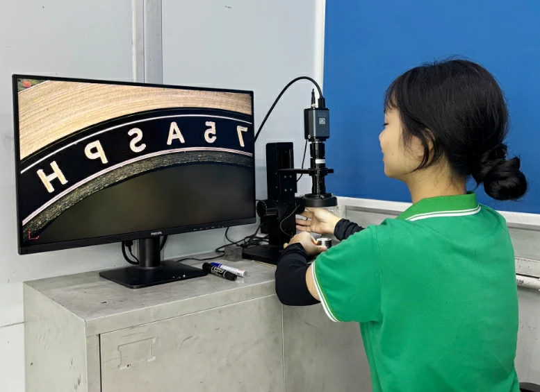
A connector might look “clean” to the human eye, but at 400x magnification, it could look like a battlefield.
1. Visual Inspection (The First Defense)
Technicians use digital microscopes to check for:
- Scratches: Linear marks caused by contaminated polishing films.
- Pits: Small holes in the glass surface.
- Cracks: Structural failures in the glass core or cladding.
2. Interferometry (The Gold Standard)
The most reliable way to verify an optical polishing service is through 3D laser interferometry, which measures the sub-micron topography of the connector end-face to ensure it meets Telcordia GR-326 standards for apex offset and radius. This is a non-negotiable requirement for military, medical, and aerospace applications.
VI. Common Challenges in Fiber Polishing
Why is it so hard to get right? Several factors can ruin a batch of connectors instantly.
- Contamination: A single grain of dust on a polishing film can leave a deep scratch across an entire batch of 24 connectors. Professional services operate in cleanroom-controlled environments.
- Pressure and Speed: If a polishing machine applies too much pressure, it creates “sub-surface damage” in the glass that isn’t visible but causes high insertion loss.
- Film Depletion: Polishing films have a limited lifespan. Using a film for “one more cycle” often results in an inconsistent finish.
VII. Professional Service vs. In-House Polishing
For many B2B companies, the “Make vs. Buy” decision is critical. While manual hand-polishing kits exist, they are rarely sufficient for modern standards.
Choosing a professional optical polishing service provides a significant ROI by eliminating the high capital expenditure of automatic polishing machines (which can cost upwards of $10,000) and 3D interferometers ($15,000+), while ensuring a 100% first-pass yield for complex connectors like MPO/MTP.
When to Outsource:
- High Volume: If you need thousands of terminations per month.
- Specialized Connectors: APC (8-degree angle) or MT-style multi-fiber connectors are extremely difficult to polish manually.
- Mission-Critical Apps: Where a single failure could lead to hours of network downtime.
VIII. Frequently Asked Questions (FAQ)
1. Can a scratched fiber connector be re-polished?
Yes. If a connector fails inspection due to light surface scratches, it can often be put back through the “Refining” and “Final Polish” stages. However, if the scratches are deep or the fiber height is already at its limit, the connector must be replaced.
2. What is the difference between PC, UPC, and APC?
- PC (Physical Contact): Basic spherical polish.
- UPC (Ultra Physical Contact): An extended polishing cycle resulting in a better surface finish and lower return loss (>-50dB).
- APC (Angled Physical Contact): The end-face is polished at an 8-degree angle. This ensures that any reflected light is coupled into the cladding rather than back into the core, providing the best return loss (>-65dB).
3. Does environmental temperature affect the polish?
Indirectly, yes. As mentioned, the “piston effect” caused by thermal expansion can cause the fiber to recede or protrude if the epoxy and curing process weren’t handled professionally.
IX. Conclusion: The Foundation of Reliable Connectivity
Optical polishing is an art form backed by rigorous physics. Whether you are building a local area network or a transcontinental subsea cable, the quality of the polish is the ultimate gatekeeper of your data.By understanding the process—from the initial de-nubbing to the final 3D interferometry check—you are better equipped to choose an Optical Polishing Service that guarantees your network stays online, efficient, and future-proof. Don’t let a micron-sized defect become a megabit-sized problem.