In the realm of high-precision engineering, the difference between a functional component and a world-class optical system often lies in dimensions invisible to the naked eye. When you are seeking a professional optical polishing service, you aren’t just buying a “shiny” surface; you are investing in the management of light. Whether you are developing high-power laser systems, semiconductor lithography tools, or advanced medical imaging devices, understanding surface roughness is the first step toward project success.
This guide explores the technical limits of modern polishing, explains the critical metrics of Ra and RMS, and provides the transparency you need to make informed procurement decisions.

I. Introduction: The Invisible Impact of Surface Finish
For many mechanical parts, “smooth” is a subjective term. In optics, smoothness is a rigorous mathematical requirement. Surface roughness refers to the high-frequency irregularities on an optical surface. While a surface might appear perfectly flat to a standard touch-probe, at the microscopic level, it resembles a mountain range.
For an optical polishing service, the goal is to reduce these “peaks and valleys” to a level where they no longer interfere with the wavefront of light. Optical polishing can achieve surface roughness levels ranging from 20Å (commercial grade) down to less than 1Å (super-polished grade), depending on the material and the polishing technique used.
Choosing the right roughness is a balance of performance and cost. Over-specifying can lead to astronomical price increases, while under-specifying can result in light scattering, loss of contrast, or even catastrophic laser damage.
II. Decoding the Language of Roughness: Ra vs. RMS
When reviewing a quote or a metrology report from an optical manufacturer, you will encounter two primary terms: Ra and RMS. Understanding the distinction is vital for accurate specification.
1. Ra (Arithmetic Average Roughness)
Ra is the most commonly used parameter in general machining. It represents the arithmetic average of the absolute values of the profile height deviations from the mean line within a sampling length. While useful, Ra can sometimes “smooth over” extreme peaks or deep scratches that might be detrimental to an optical system.
2. RMS (Root Mean Square Roughness)
In the precision optics industry, RMS (Rq) is the preferred metric for surface roughness because it is more sensitive to large deviations from the mean surface, providing a better statistical representation of the “peaks and valleys” that contribute to light scattering. Because the calculation squares the values, a single deep scratch will impact the RMS value more significantly than the Ra value.
Ra vs. RMS Comparison
| Feature | Ra (Arithmetic Average) | RMS (Root Mean Square) |
| Calculation | Average of absolute deviations | Square root of the average of squares |
| Sensitivity | Stable, ignores outliers | High sensitivity to extreme peaks/valleys |
| Industry Usage | General manufacturing, commercial optics | High-precision laser and UV optics |
| Typical Value | Usually lower than RMS | Usually 1.1 to 1.4 times higher than Ra |
Important Note: There is no universal “constant” to convert Ra to RMS. While a ratio of 1.11 is often cited for pure sine waves, real-world polished surfaces vary based on the polishing grain and tool paths. Always specify which metric you require in your RFQ (Request for Quote).
III. Benchmarking “Achievable” Results: From Commercial to Super-Polished
What is actually possible in a modern optics shop? The “achievable” roughness is heavily dictated by the polishing time, the environment, and the equipment used.
Surface Roughness Grades in Optical Polishing
| Grade | Roughness (Ra/RMS) | Common Applications |
| Commercial | 20Å – 50Å | Protective windows, consumer camera lenses, lighting. |
| Precision | 5Å – 10Å | Scientific imaging, standard laser optics, microscopy. |
| High-Precision | 2Å – 5Å | High-power laser systems, beam splitters, mirrors. |
| Super-Polished | < 1Å – 2Å | X-ray optics, UV lithography, gravitational wave detectors. |
To achieve a super-polished surface with roughness below 1 Angstrom (Å), the optical polishing service must utilize specialized pitch polishing or Magnetorheological Finishing (MRF) in a temperature-controlled, ultra-clean environment. At this level, even a single speck of dust in the polishing slurry can create a “dig” that ruins the specification.
IV. Critical Factors That Influence the Final Roughness
Achieving sub-nanometer roughness isn’t just about “polishing longer.” It is a complex interplay of material science and mechanical engineering.
1. Substrate Material
The “polishability” of a material is often limited by its molecular structure.
- Amorphous Materials: Materials like Fused Silica and N-BK7 are the gold standard for low roughness. Because they lack a crystalline grain structure, they can be polished to incredibly smooth finishes (often < 1Å).
- Crystalline Materials: Materials like Silicon, Germanium, or Calcium Fluoride (CaF2) are more challenging. The polishing process must account for the crystal orientation, and “pull-outs” (small bits of crystal breaking away) can limit the minimum achievable roughness.
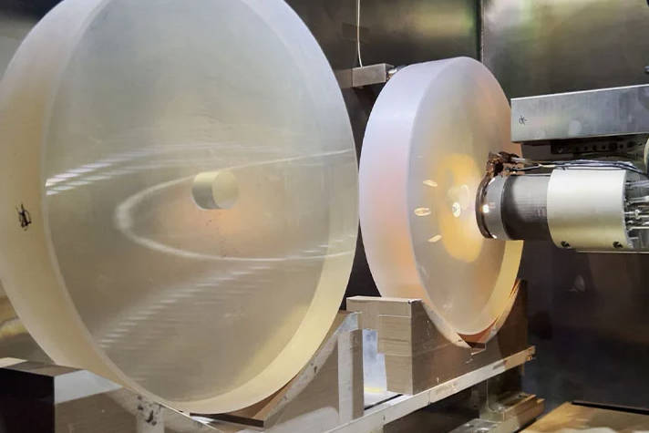
2. Polishing Techniques
An expert optical polishing service will choose a method based on your target Ra:
- Pitch Polishing: The traditional method using a beeswax or petroleum-based pitch lap. It remains the best way to achieve ultra-low roughness because the pitch “flows” to perfectly match the surface.
- Magnetorheological Finishing (MRF): A deterministic process using a magnetic fluid. It is excellent for correcting surface figure (shape) and can reach very low roughness, though it is often used as a final “correction” step.
- Chemical Mechanical Polishing (CMP): Common in the semiconductor industry, CMP uses chemical etching combined with mechanical abrasion to achieve atomic-level smoothness on wafers.
V. Why Does It Matter? The Practical Consequences of Roughness
Why should you pay more for 2Å instead of 20Å? The physics of light provides the answer.
1. Light Scattering (The “Halo” Effect)
The rougher a surface, the more it acts like a diffuser. Surface roughness is directly proportional to Total Integrated Scatter (TIS); as roughness increases, light is diverted from the primary path, reducing the contrast and “signal-to-noise” ratio of the optical system. In imaging, this looks like a hazy “halo” around bright objects.
2. Laser Induced Damage Threshold (LIDT)
For high-power lasers, roughness is a safety hazard. Peaks on the surface can act as “micro-lenses” that focus laser energy into small spots, while valleys can trap polishing contaminants. Both lead to localized heating and the eventual cracking or “pitting” of the optic.
3. Thin-Film Coating Performance
Most optics are coated with dielectric layers. High surface roughness can lead to poor coating adhesion and increased absorption within the coating layers, which significantly reduces the efficiency of anti-reflective or high-reflective treatments.
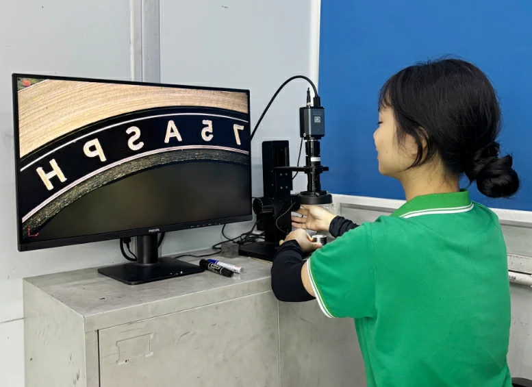
VI. Metrology: How We Prove What We Achieve
If you cannot measure it, you cannot guarantee it. A professional optical polishing service must use non-contact metrology to verify roughness without damaging the surface.
- White Light Interferometry (WLI): The workhorse of the industry. It uses the interference patterns of light to map the 3D topography of the surface with sub-nanometer vertical resolution.
- Atomic Force Microscopy (AFM): When you need to measure in the sub-Angstrom range, AFM is used. A tiny probe “feels” the surface at an atomic level. While slow, it is the ultimate verification for super-polished optics.
VII. Expert Advice for Procurement and Engineering
When requesting a quote for optical polishing services, consider the following to ensure you get the best value:
- Specify the Clear Aperture: Does the entire part need to be 2Å, or just the center 80%? Specifying a smaller “clear aperture” for the highest precision can significantly reduce costs.
- Ask for a Metrology Report: Never accept a “Certificate of Compliance” alone. Request the actual interferometer or AFM maps. A reputable partner will always provide this data.
- Define the Material Grade: If you want a 1Å finish, you must start with high-quality, inclusion-free synthetic fused silica. You cannot achieve super-polish results on low-grade commercial glass.
VIII. Conclusion: Finding the Right Balance
Surface roughness is a critical specification that dictates the performance, longevity, and cost of your optical components. While the transition from 10Å to 1Å represents a massive leap in technical difficulty, for many modern applications, it is the difference between a failed experiment and a breakthrough discovery.
At our facility, we view optical polishing as a partnership between our master opticians and your engineering team. We don’t just aim for a number; we aim for the performance your application demands.