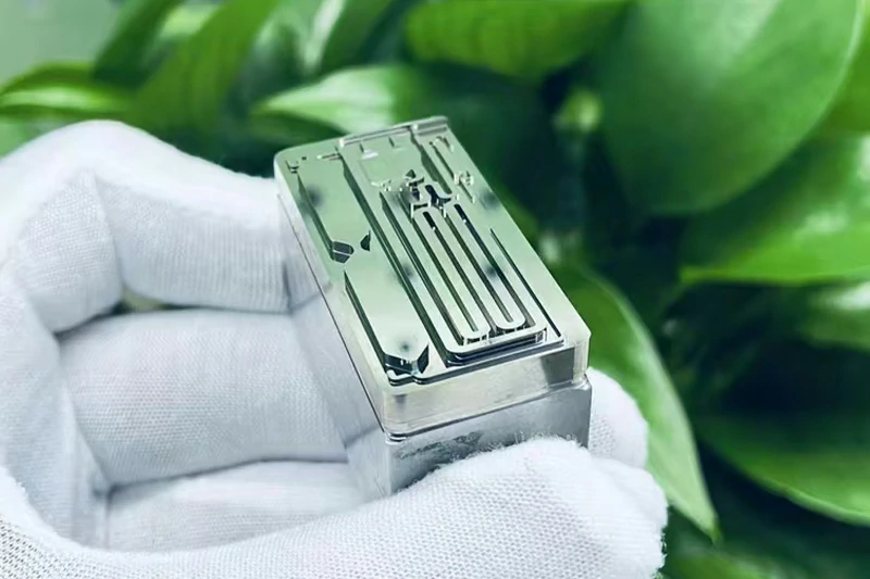
Freeform optics represent the frontier of optical system design, enabling performance improvements and system miniaturization impossible with traditional spherical or aspherical surfaces. However, freeform optics manufacturing presents formidable challenges that demand advanced equipment, refined processes, and deep expertise.
The transition from rotationally symmetric optics to surfaces with no axis of symmetry fundamentally changes manufacturing requirements. Optical designers increasingly specify freeform elements to reduce element counts, correct aberrations across wide fields of view, and enable novel system architectures for augmented reality displays, automotive lighting, high-reliability optical sensors, and medical instruments.
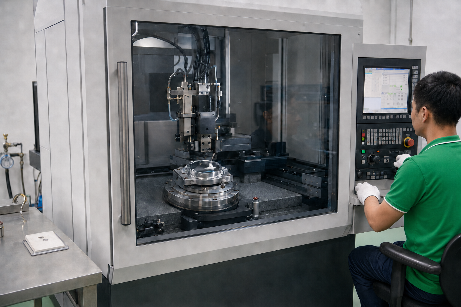
YISHUN Optical’s precision manufacturing capabilities—including Moore diamond turning, RODERS five-axis machining, and advanced finishing processes—enable production of complex freeform optics meeting the most demanding specifications.
Key Takeaway:
- Freeform optics enable unprecedented design freedom but require non-rotationally symmetric manufacturing approaches
- Multi-axis CNC machining with sub-micrometer accuracy forms the foundation of freeform fabrication
- Diamond turning and milling address different freeform geometries and material requirements
- Surface finishing of freeform optics presents unique challenges due to geometric complexity
- Metrology of freeform surfaces requires advanced coordinate measuring and interferometric techniques
What Are Freeform Optics?
Freeform optics are optical surfaces that lack rotational symmetry, featuring mathematically complex profiles that can include:
- Zernike polynomial surfaces: Described by combinations of orthogonal Zernike terms
- XY polynomial surfaces: Defined by polynomial functions in X and Y coordinates
- Q-type aspheres: Specialized surfaces optimized for manufacturing
- Arbitrary spline surfaces: Defined by control point grids
- Toric and bitoric surfaces: Cylindrical symmetry combined with spherical curvature
- Off-axis segments: Portions of larger rotationally symmetric surfaces
Applications Driving Freeform Adoption
| Application | Freeform Benefits |
|---|---|
| AR/VR Headsets | Compact, wide field-of-view imaging with minimal elements |
| Automotive Lighting | Precise beam shaping, pedestrian detection illumination |
| Head-Up Displays | Distortion-free imaging across viewing angles |
| high-reliability optical Sensors | Lightweight, multi-functional optics for imaging and communication |
| Medical Imaging | Endoscopic and laparoscopic optics with extended depth of field |
| Laser Scanning | High-speed, precise beam deflection and shaping |
| Systems | Compact EO/IR optics with wide-angle capability |
Manufacturing Challenges for Freeform Optics
The absence of rotational symmetry creates challenges across the entire manufacturing workflow:
Challenge 1: Non-Rotationally Symmetric Material Removal
Traditional optical manufacturing relies on rotation, enabling:
- Continuous tool path with constant velocity
- Uniform material removal distribution
- Simplified process development
Freeform surfaces require point-by-point or path-based material removal without these simplifications:
- Tool paths must follow mathematically complex trajectories
- Material removal varies continuously across the surface
- Feed rates and depths of cut must adapt to local surface geometry
- Tool engagement angles change throughout the path
Challenge 2: Tool Geometry and Access
Fabricating concave or internal freeform features introduces severe tool access constraints:
- Standard cutting tools cannot reach deep cavities with complex bottom geometry
- Tool overhang requirements increase with feature depth
- Vibration and deflection become critical limiting factors
- Tool path planning must avoid collisions with workpiece geometry
Challenge 3: Surface Quality Across Complex Topography
Maintaining consistent surface quality proves difficult when:
- Cutting speeds vary with position due to changing surface normals
- Effective rake and clearance angles change continuously
- Chips must evacuate from complex geometry
- Coolant delivery must reach all active cutting zones
Challenge 4: Metrology and Verification
Measuring freeform surfaces challenges traditional optical inspection:
- Coordinate measurement machines must reach all surface points
- Interferometric testing requires specialized null optics or computed holograms
- Surface form measurement accuracy degrades with geometric complexity
- Stitching interferometry adds complexity and measurement time
Challenge 5: Process Development Complexity
Process parameters optimized for one surface location may fail elsewhere:
- A single parameter set cannot achieve uniform results across the surface
- Process models must account for full surface geometry
- Iterative development cycles lengthen delivery schedules
- Statistical process control becomes more challenging
Manufacturing Solutions and Technologies
Addressing freeform optics manufacturing challenges requires integrated solutions spanning equipment, tooling, process, and metrology:
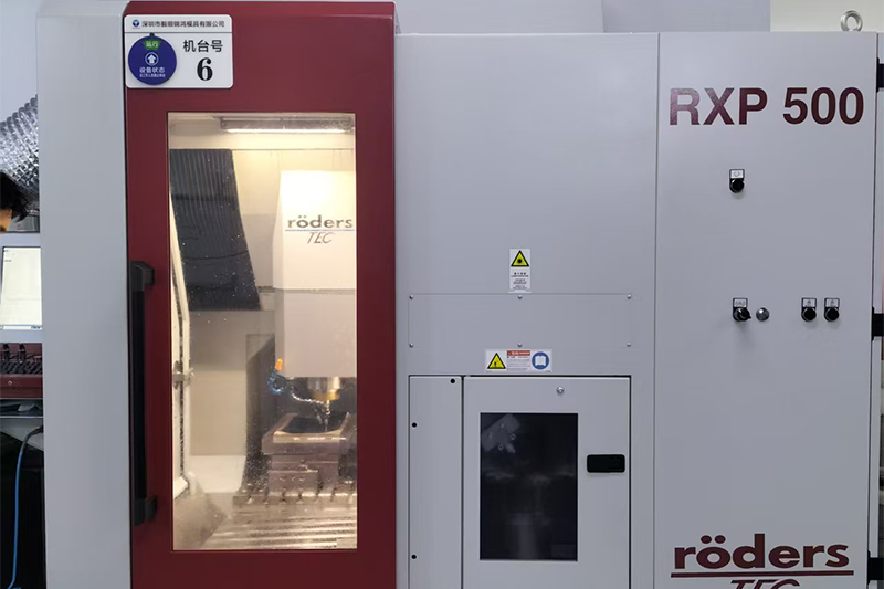
Solution 1: Five-Axis CNC Machining
Five-axis machining centers like the RODERS RXP500DS provide the geometric flexibility required for freeform fabrication:
Key Capabilities:
- Simultaneous control of five axes enables tool orientation perpendicular to local surface
- Complex tool paths with continuous interpolation
- Reduced tool overhang through optimal machine positioning
- High-speed spindle options for fine finishing passes
| RODERS RXP500DS Specifications | Value |
|---|---|
| Positioning Accuracy | ±1 μm |
| Repeatability | ±0.5 μm |
| Spindle Speed | 12,000 rpm |
| Control System | Siemens 840D |
| Rotary Axis Accuracy | ±2 arc seconds |
Five-axis machining handles both metal and polymer freeform substrates, enabling rapid prototyping and medium-volume production with excellent surface quality.
Solution 2: Ultra-Precision Diamond Turning
For crystalline and soft optical materials, diamond turning delivers unmatched surface quality:
Brysen MM-1212G Ultra-Precision Machine Specifications:
- X/Y/Z resolution: 0.1 μm
- Spindle speed: 0-2000 rpm (variable)
- Contour accuracy: ±0.5 μm
- Surface roughness: Ra <10 nm
Diamond turning excels for:
- Infrared materials (germanium, zinc selenide, zinc sulfide)
- Optical plastics and polymers
- Soft metals (aluminum, copper, brass)
- Crystalline materials (calcite, sapphire)
The technique produces freeform surfaces directly through controlled diamond tool motion along mathematically-defined paths.
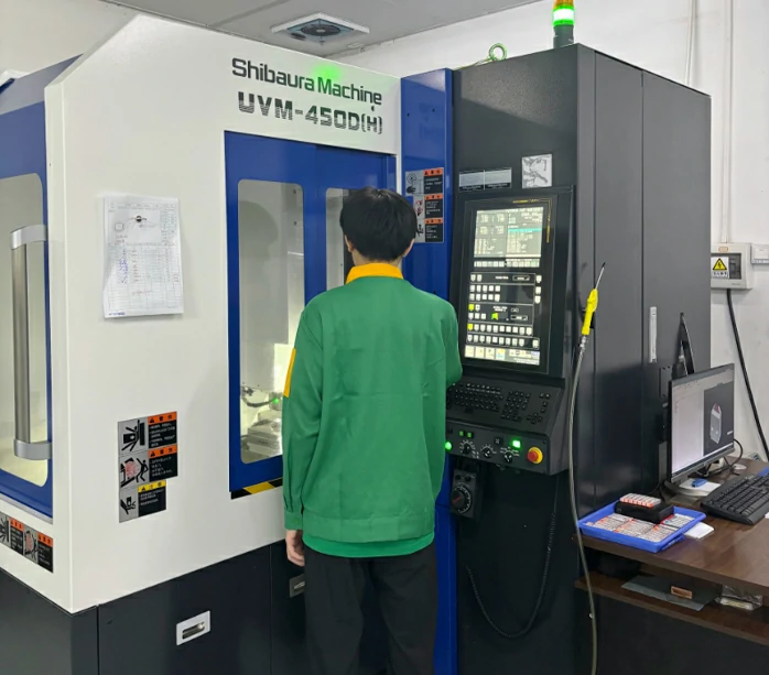
Solution 3: Multi-Axis Milling with Ball-End Tools
Ball-end milling balances material removal efficiency with surface quality:
Process Characteristics:
- Ball-end geometry provides consistent cutting edge geometry regardless of surface orientation
- Tool path planning using spiral, raster, or offset strategies
- Multiple finishing passes with decreasing step-over distance
- Semi-finish passes remove bulk material; finish passes achieve final geometry
Optimal Parameters for Freeform Milling:
| Pass Type | Tool Diameter | Step-Over | Depth of Cut | Feed Rate |
|---|---|---|---|---|
| Roughing | 3-6mm | 0.5-1mm | 0.5-2mm | High |
| Semi-Finish | 1-3mm | 0.1-0.3mm | 0.1-0.3mm | Medium |
| Finishing | 0.5-1mm | 0.02-0.05mm | 0.02-0.05mm | Low |
| Super-Finish | 0.2-0.5mm | 0.005-0.01mm | 0.005mm | Very Low |
Solution 4: Grinding Followed by Polishing
Machined freeform surfaces require finishing to achieve optical-quality surfaces:
Freeform Polishing Approaches:
- Computer-Controlled Polishing (CCP)
- Uses pre-defined removal functions
- Optimizes tool path for uniform material removal
- Examples: Ion Beam Figuring (IBF), Magnetorheological Finishing (MRF)
- Stress Polishing
- Applies controlled pressure to deform surface during polishing
- Enables aspheric corrections during polishing
- Manual/Robotized Polishing
- Operator-controlled or robot-assisted material removal
- Flexible for complex geometries
- Highly dependent on operator skill
- Hybrid Approaches
- Combine CCP for global figure correction with manual polishing for local refinement
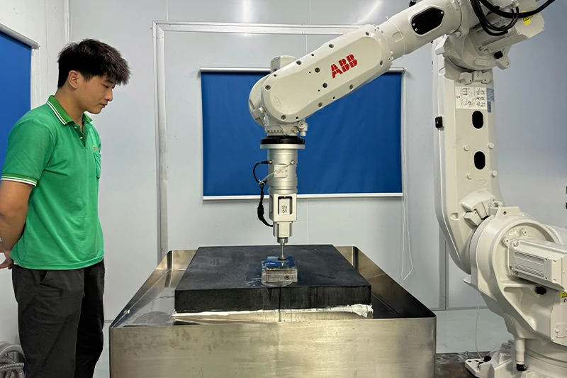
Solution 5: Advanced Metrology Systems
Comprehensive freeform verification requires multiple measurement techniques:
Coordinate Measurement:
- Multi-axis CMMs with touch probes
- Scanning white light interferometry
- Laser scanning for high-speed data acquisition
Interferometric Testing:
- Computer-Generated Holograms (CGHs): Custom null optics for specific freeform designs
- Stitching Interferometry: Combines multiple sub-aperture measurements
- Scanning Deflectometry: Measures surface slopes directly for complex geometries
Surface Roughness:
- Atomic Force Microscopy (AFM) for nano-scale characterization
- Phase-shifting interferometry for larger areas
- Optical profilometers for rapid roughness assessment
Material Considerations for Freeform Optics
Material selection influences manufacturing approach:
| Material | Manufacturing Method | Key Considerations |
|---|---|---|
| Aluminum (6061, 7075) | Diamond turning, milling | Excellent machinability, requires coating |
| Brass/Copper | Diamond turning, milling | Good thermal conductivity, high damping |
| Germanium | Diamond turning, grinding | Infrared applications, brittle |
| Zinc Selenide | Diamond turning, polishing | Laser applications, toxic machining concerns |
| Fused Silica | Grinding, polishing | UV/visible applications, high hardness |
| PMMA/Polycarbonate | Milling, diamond turning | Low-cost prototyping, abrasion sensitivity |
| Sapphire | Grinding, polishing | Extreme environment, difficult to machine |
| Silicon Carbide | Grinding, polishing | High stiffness, difficult material |
Process Development Workflow for Freeform Optics
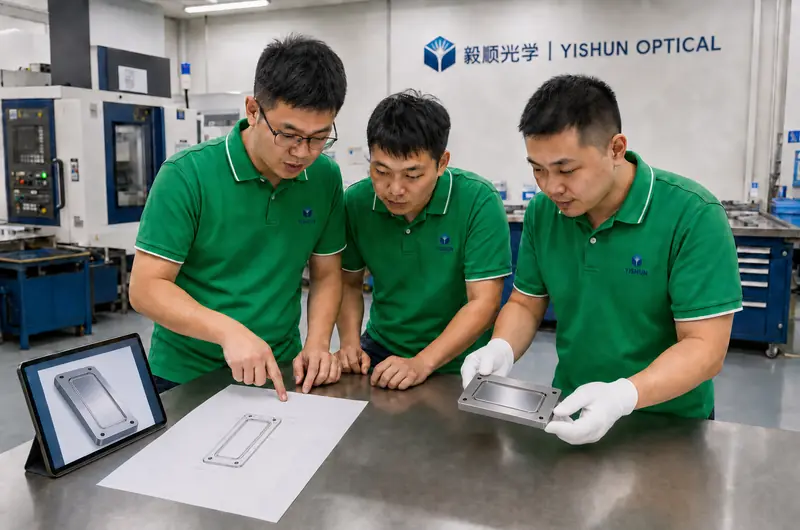
YISHUN Optical’s systematic approach ensures consistent freeform manufacturing:
Phase 1: Design Review and Manufacturing Assessment
- Evaluate surface geometry for manufacturability
- Identify potential problem areas (deep cavities, sharp features)
- Recommend design modifications if needed for manufacturing
- Establish achievable tolerance budgets
Phase 2: Process Development
- Select appropriate manufacturing technology (turning, milling, grinding)
- Develop tool path strategies and parameters
- Conduct trial machining with coordinate verification
- Iterate process parameters for optimization
Phase 3: Surface Finishing Development
- Evaluate starting surface quality from machining
- Select finishing approach based on requirements
- Develop removal function or process parameters
- Verify final surface quality meets specifications
Phase 4: Metrology Validation
- Characterize surface using appropriate techniques
- Compare measurements against design intent
- Verify repeatability and reproducibility
- Document process capability
Phase 5: Production Qualification
- Qualify process with statistical evidence
- Establish process controls and inspection points
- Define corrective action procedures
- Train production personnel
Design for Manufacturability (DFM) Guidelines
Collaboration between optical designers and manufacturers improves freeform manufacturability:
Recommended DFM Practices:
- Minimize Surface Slope Gradients: Steep changes in surface slope challenge tool access and finishing
- Allow Adequate Clearances: Provide tool clearance around edges and features
- Consider Machining Direction: Specify surfaces accessible from single setup when possible
- Balance Accuracy Requirements: Apply tighter tolerances only where functionally necessary
- Anticipate Metrology Needs: Consider how surfaces will be measured during design
- Select Appropriate Materials: Match material properties to manufacturing capability
- Specify Realistic Surface Roughness: Ra <5nm on freeform surfaces significantly increases cost and time
Quality Assurance for Freeform Optics
YISHUN Optical’s freeform quality assurance encompasses:
- Incoming Material Verification: Material identification, dimensional verification
- In-Process Inspection: Coordinate measurement at critical stages
- Final Surface Form: Interferometric or CMM verification to design intent
- Surface Roughness: Optical profilometry and microscopy
- Functional Testing: Where applicable, optical performance testing
- Documentation: Complete manufacturing records and certificates of conformance
Conclusion
Freeform optics manufacturing presents genuine challenges—geometric complexity, tool access constraints, and demanding metrology requirements—but these challenges are surmountable with appropriate equipment, process expertise, and systematic methodology.
Success in freeform manufacturing requires:
- Advanced multi-axis equipment capable of achieving sub-micrometer accuracy
- Deep process knowledge spanning machining, grinding, and polishing
- Comprehensive metrology for complex surface verification
- Collaborative design that considers manufacturing capabilities
- Quality systems ensuring consistency across production
YISHUN Optical’s investment in advanced manufacturing equipment—including RODERS five-axis machining centers and Moore diamond turning systems—combined with 20+ years of precision optics expertise, positions us to deliver freeform components meeting your most demanding specifications.
Contact info@yishunoptical.com or visit yishunoptical.com to discuss your freeform optics manufacturing requirements.
YISHUN Optical delivers ISO 9001:2015 certified freeform optical components for high-reliability optical, automotive, medical, and consumer applications. Our comprehensive capabilities span design consultation, manufacturing, and metrology.
Frequently Asked Questions
What is the difference between freeform optics and aspheric optics?
Aspheric optics have rotational symmetry—they maintain the same profile regardless of rotation angle around their optical axis. Freeform optics lack rotational symmetry entirely, featuring mathematically complex surfaces that vary in all directions. This fundamental difference means freeform optics require non-rotationally symmetric manufacturing, while aspheric optics can be produced using conventional CNC lathe-based processes.
What is the typical surface accuracy achievable for freeform optics?
Surface accuracy for freeform optics typically ranges from λ/4 to λ/20 (0.15μm to 0.03μm), depending on specification requirements, material, and manufacturing approach. Diamond-turned freeform surfaces can achieve λ/4-λ/10, while polished freeform surfaces using computer-controlled techniques can reach λ/20 or better.
Can freeform optics be manufactured in any material?
Most optical materials can be fabricated as freeform surfaces, though manufacturing approach varies significantly. Metals and polymers are readily machined using CNC milling or diamond turning. Optical glasses, crystalline materials, and ceramics require grinding and polishing processes. Sapphire and silicon carbide present the greatest manufacturing challenges due to their hardness.
How is metrology performed on freeform optics?
Freeform metrology typically employs coordinate measuring machines (CMMs) with touch probes or scanning capabilities for geometric verification. For interferometric testing, computer-generated holograms (CGHs) serve as null optics, or stitching interferometry combines multiple sub-aperture measurements. Scanning profilometers measure surface form directly for complex geometries.
What is the typical lead time for freeform optics?
Lead times for freeform optics range from 2-8 weeks depending on complexity, material, accuracy requirements, and order volume. Simple aluminum freeform elements may deliver in 2-3 weeks, while complex precision freeform optics requiring extensive process development may require 6-8 weeks or longer.
What are the cost implications of freeform optics compared to traditional optics?
Freeform optics typically cost 2-5× more than equivalent aspheric or spherical optics due to increased manufacturing complexity, extended process development time, and demanding metrology requirements. However, freeform optics can reduce overall system cost by reducing element count, simplifying assembly, and improving performance—making system-level cost comparisons often favorable.
How do you ensure consistency in freeform optics production?
Consistency requires rigorous process control, including validated manufacturing processes with statistical evidence, calibrated equipment with documented capability, in-process inspection at critical stages, and comprehensive documentation of all manufacturing parameters. YISHUN Optical’s ISO 9001:2015 certified quality system ensures production consistency.
Can freeform optics be coated?
Yes, freeform optics can receive standard optical coatings including anti-reflection, high-reflector, and protective coatings. However, coating uniformity on complex freeform geometry requires specialized coating techniques and may have more variation than planar surfaces. Our coating partners evaluate each freeform design for coating feasibility and specify appropriate processes.