
From a Single Optical Insert to a Complete Automotive Lighting Project
Automotive optical tooling problems rarely belong to one category. A project may involve mirror appearance, freeform form control, light-guide features, reflective geometry and microstructures at the same time.
Choose the application closest to your project, or start from the machining problem you need to solve.
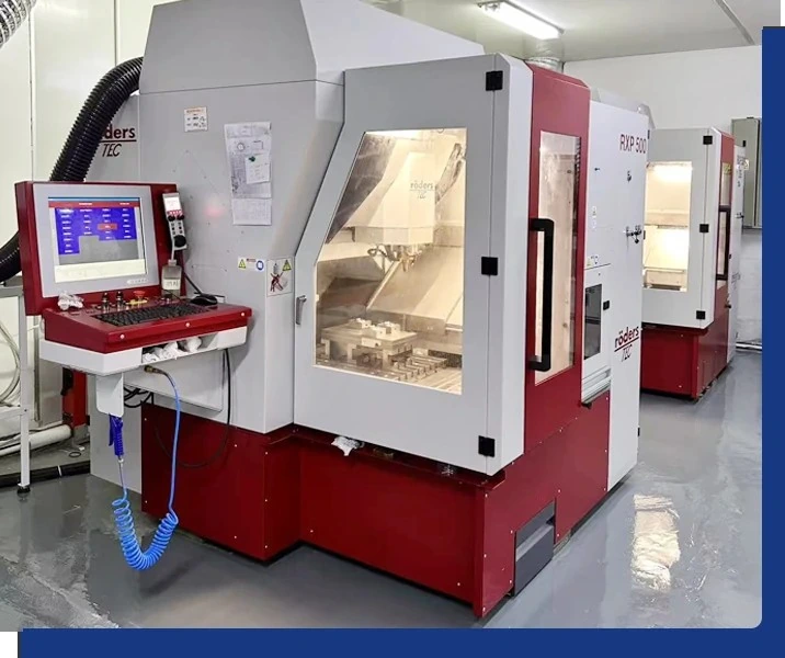
Which machining risk is blocking your project?
Customers do not usually change suppliers because a machine specification looks different. They change when the current process cannot solve the real surface, geometry or consistency problem.
Choose the insert by optical function
Each category has a different failure mode, so each page focuses on the machining decisions, acceptance logic and project data that matter for that specific component.
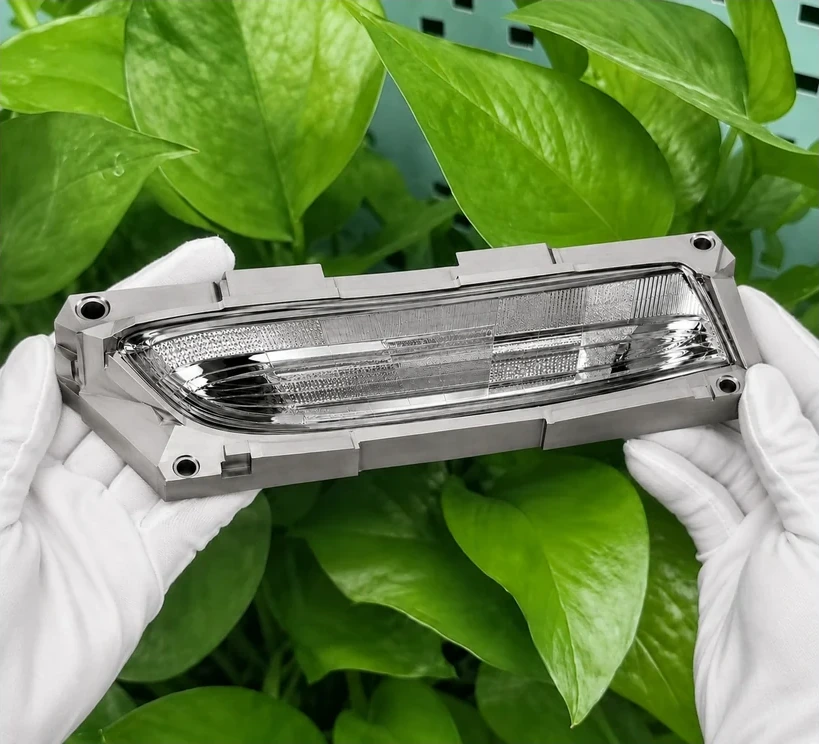
Tail Light Optical Mold Inserts
Reflective zones, transitions and appearance-critical surfaces.
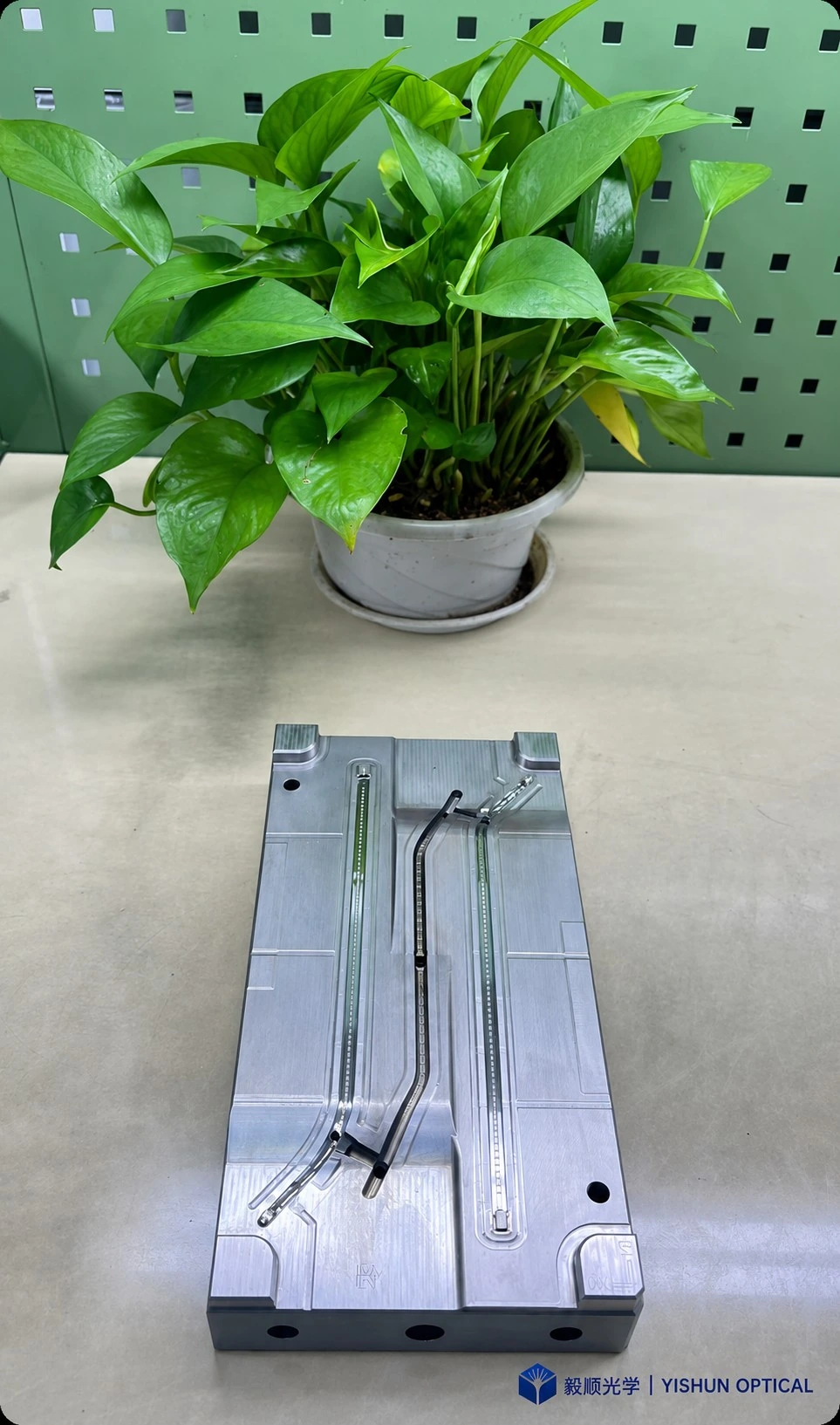
Long Optical Path Mold Inserts
Fine features, path consistency and matching relationships.
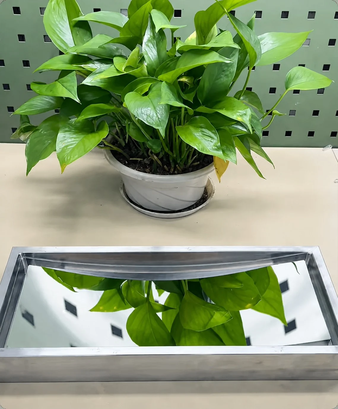
Freeform Reflective Inserts
Surface form, reflection continuity and tool-mark control.
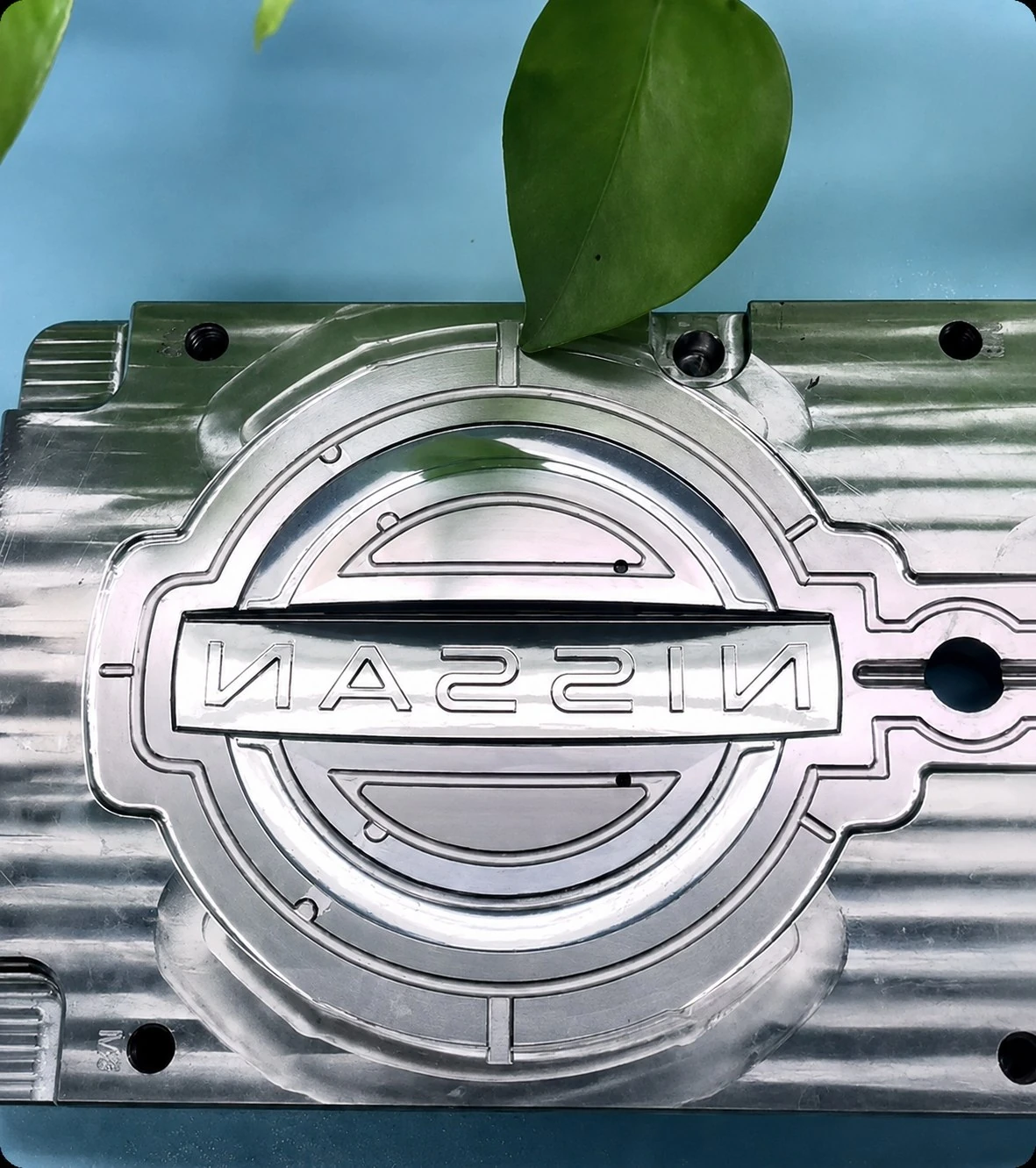
Automotive Emblem Inserts
Mirror finish, logo definition and plating-related appearance risk.
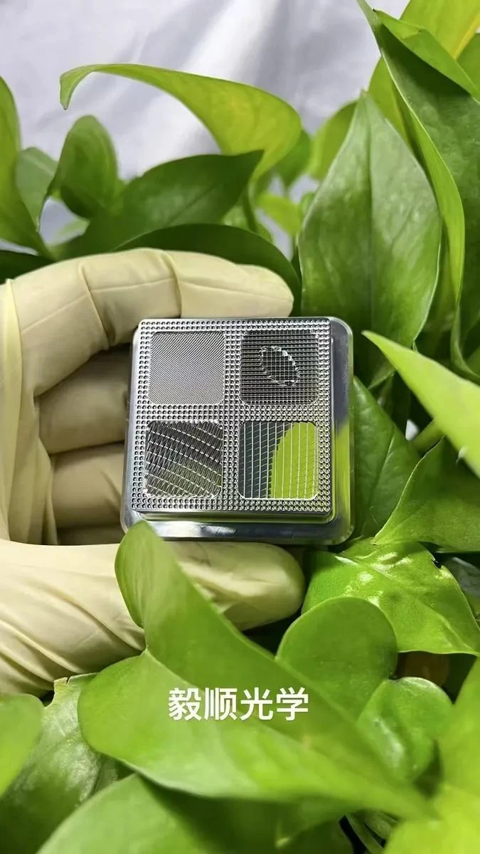
Lighting Pattern & Microstructure Inserts
Facet geometry, micro arrays, groove continuity and pattern repeatability.
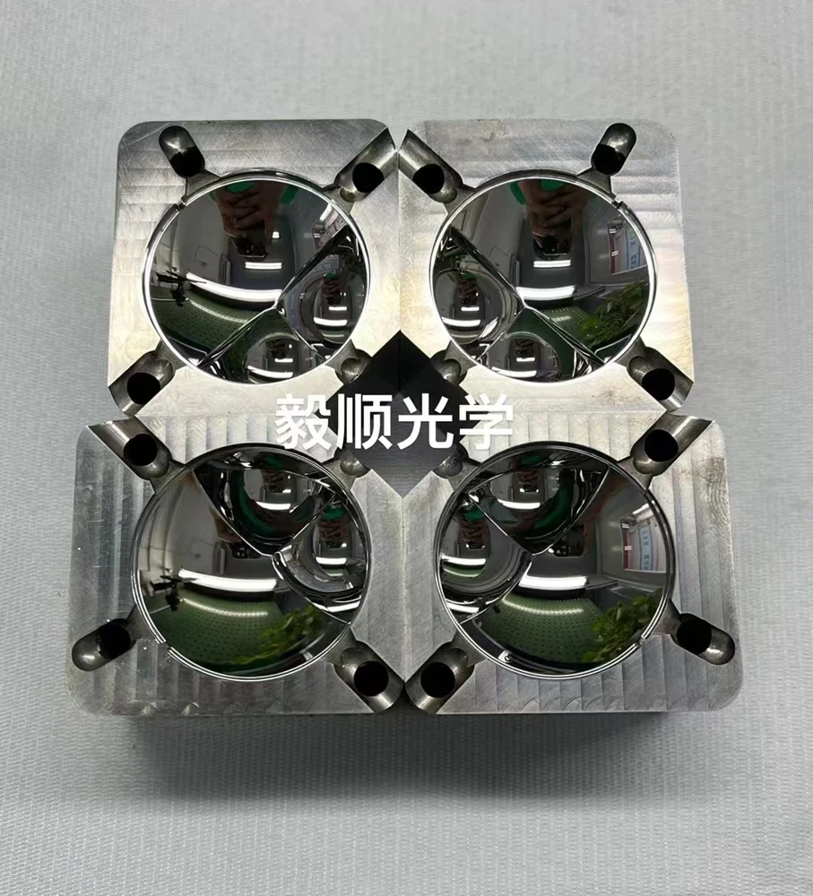
Headlamp Lens Mold Insert
Optical lens inserts requiring stable surface finish, freeform or aspheric form control and optical-zone consistency.
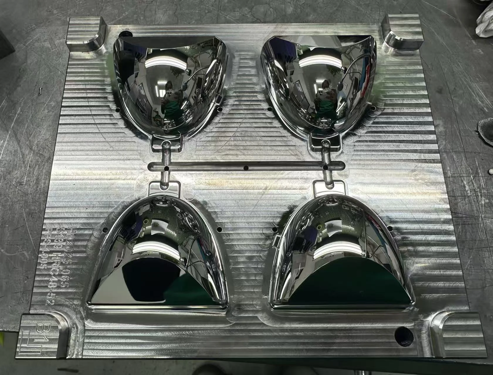
Headlamp Reflector Mold Insert
Complex reflector inserts requiring stable reflective geometry, surface continuity and controlled mirror finishing.
Not every optical mold insert needs the same control strategy
This matrix gives customers a faster way to understand which machining risks usually deserve the most attention for each automotive optical application.
One manufacturing system, adapted to different automotive optical risks
Yishun’s automotive optical projects combine precision machining, five-axis mirror machining, controlled finishing and inspection according to the actual insert structure. The process changes when the optical risk changes.
Review the risk before choosing the machining route
Send the drawing
2D, 3D, material, tolerance and optical-zone information.
Identify the functional surface
Separate mirror, freeform, structural and reference areas.
Review machining risk
Check tool access, finishing allowance, edge protection and datum stability.
Define inspection logic
Agree what is measured on the insert and what still requires downstream optical validation.
Start production
Use the process route that fits the real optical requirement rather than a generic sequence.
Not sure which page or machining route fits your project?
Send the drawing and describe the optical or machining problem. Our team can first identify the critical surface, likely failure risk and suitable review route before you decide how to proceed.