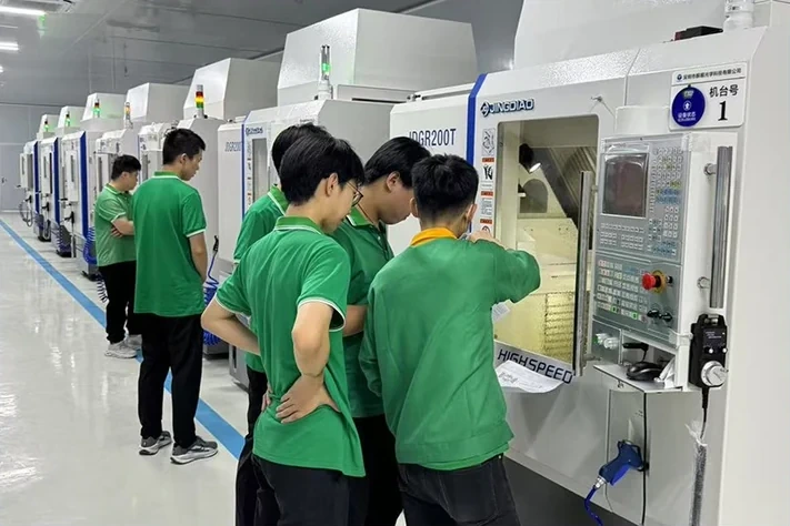
Automotive Tail Light Optical Mold Insert Machining
We help control optical surface quality, reflection continuity, datum matching, and consistency in complex tail light inserts—focusing on the machining issues that directly affect final lighting performance.
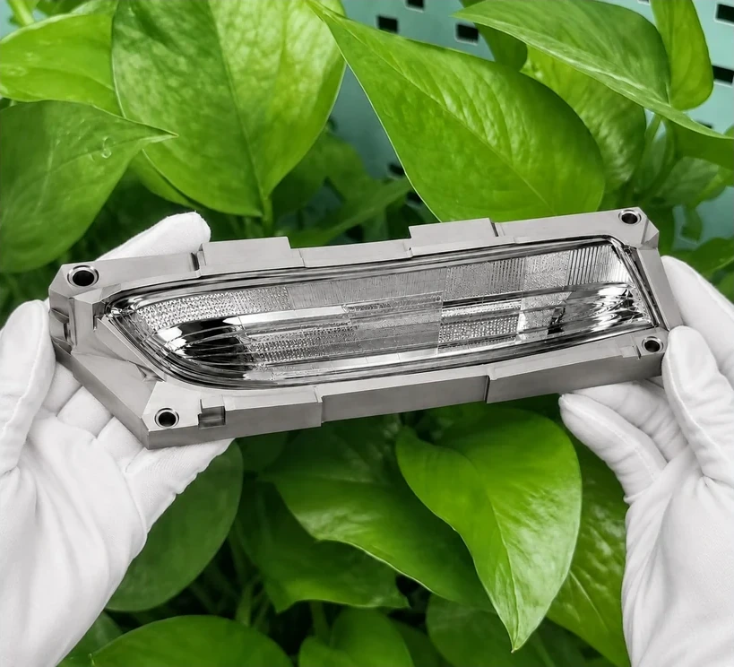
Common Problems in Tail Light Optical Insert Projects
Reflection lines look inconsistent
Small form errors or tool-mark patterns can interrupt reflection continuity even when roughness values appear acceptable.
Local tool marks or waviness
Visible under lighting conditions and difficult to remove without disturbing the intended optical geometry.
Geometry shift between zones
Mismatch between optical areas and reference features can create optical and assembly errors.
Poor cavity-to-cavity consistency
Variation between inserts can lead to inconsistent lighting performance in multi-cavity projects.
A Real Project Situation
A customer’s tail light insert showed acceptable roughness values, but reflection continuity was still unstable at specific viewing angles. The transition between key optical areas and reference features also showed visible inconsistency.
Instead of simply chasing a lower Ra value, we reviewed the structure, machining path, local geometry transition, and the relationship between optical zones and datums.
By controlling the insert as a complete optical structure, the critical reflection areas became more stable and the project moved closer to the intended lighting result.
Results Achieved
What We Control During Machining
Optical Surface Continuity
- Smooth form transitions
- Consistent reflection flow
- Controlled surface form
Mirror Finish Stability
- Stable mirror-level finish
- Tool-path optimization
- Process consistency
Edge & Feature Definition
- Clean feature boundaries
- Preserve fine details
- Avoid over-correction
Datum & Assembly Relationship
- Accurate datum surfaces
- Stable matching features
- Reduced geometry shift
Localized Defect Control
- Tool-mark suppression
- Waviness reduction
- Localized correction strategy
Cavity-to-Cavity Repeatability
- Consistent machining logic
- Process parameter control
- Reduced variation
Technical Capability
| Category | Capability |
|---|---|
| Material | S136 / stainless steel / tool steel |
| Surface Finish | Up to optical mirror level, depending on material, geometry, and project requirement. |
| Typical Structures | Reflective surfaces, complex optical contours, segmented geometry, and appearance-critical surfaces. |
| Machining Focus | Form control, tool-mark suppression, optical-zone consistency, and reference-feature matching. |
| Project Support | Drawing review, manufacturability evaluation, process planning, and inspection feedback. |
Supported Insert Configurations
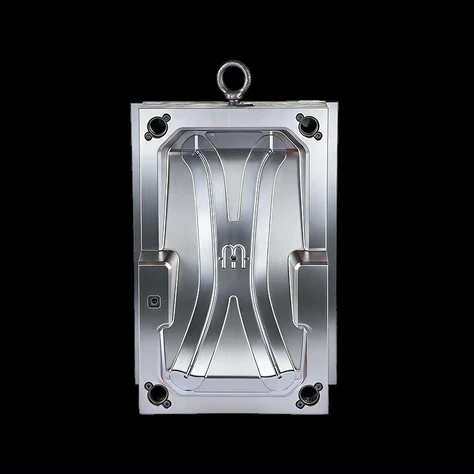
Single-Cavity Optical Insert
For dedicated optical surfaces requiring controlled geometry and mirror finish.
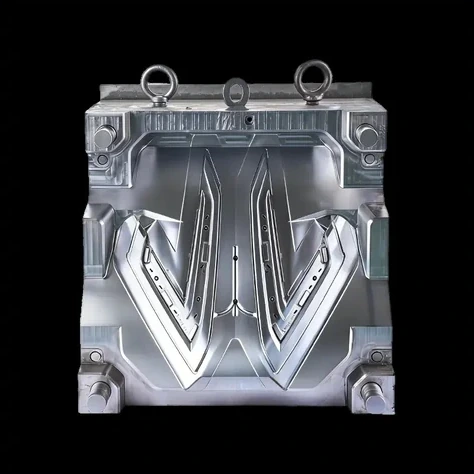
Multi-Cavity Tail Light Insert
Focused on repeatability and consistency between cavities and related optical surfaces.
Reflective Tail Light Mold Insert
Suitable for large visible optical areas and structured reflective surface control.
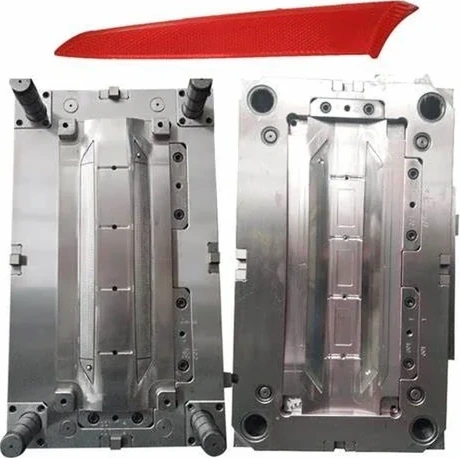
Tail Lamp Mold Core
Suitable for long narrow structures and appearance-critical lighting components.
Problems and Solutions
What We Need Before Review
- 2D / 3D drawings (STEP / IGES / PDF)
- Material and hardness requirement
- Critical optical zones and key dimensions
- Appearance or reflection requirements
- Matching or replacement context
- Existing defect photos or reference samples, if available
FAQ
Can you help review difficult tail light insert drawings?
Yes. We can review the structure, critical optical zones, machining risks, and the relationship between optical surfaces and reference features before machining.
Do you only focus on roughness values?
No. Roughness is only one part of the result. Surface form, tool marks, waviness, zone continuity, and optical behavior must also be considered.
Can you support appearance-critical reflective surfaces?
Yes, when the project requirements and surface zones are clearly defined during the review stage.
Can you support replacement or matching projects?
Yes. The existing assembly relationship, datum definition, and matching requirements should be reviewed together with the new insert.
What information helps you evaluate feasibility faster?
Clear drawings, material, hardness, key optical zones, appearance requirements, existing defect information, and reference samples are especially useful.
Working on a difficult tail light optical insert project?
Let’s discuss your drawings and risk points early so the machining plan can focus on the areas that truly affect performance, matching, and consistency.