
A phone housing may look simple in CAD, but its visible surface is unforgiving. When the finished shell is turned under light, a faint periodic mark, local wave, softened edge, or small cavity-to-cavity difference can be easy to see. Yishun Optical provides mobile phone housing mirror mold insert machining for these appearance-critical surfaces.
We do not start with a roughness value alone. First, we identify where the customer will look, which reflected lines must remain smooth, which edges must stay defined, and which datums connect the visible surface to assembly. That gives us a practical basis for machining and inspection.
Product Introduction
Use: A mobile phone housing mirror mold insert transfers the visible exterior geometry to a molded rear cover or housing shell. Depending on the design, the agreed insert scope may include a broad A-surface, curved perimeter, side walls, decorative borders, openings, corners, parting-line features, and locating datums.
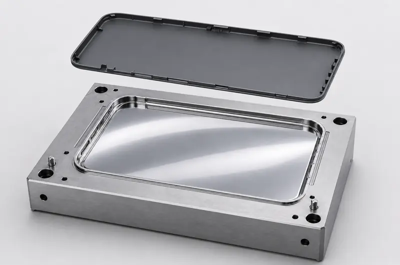
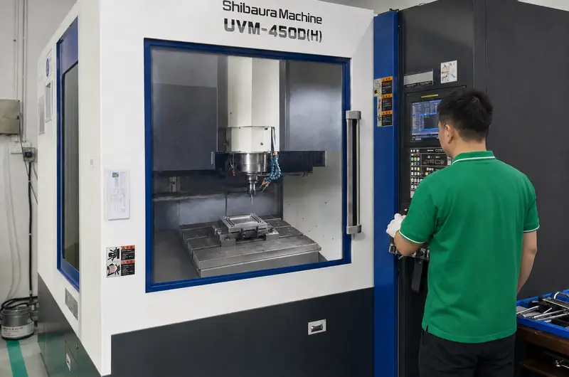
Production process: We select the process after reviewing the material, hardness, surface geometry, smallest radius, feature access, and tolerance. The route may include ultra-precision machining, five-axis mirror machining, precision grinding, or another controlled precision process. When the material and geometry are suitable, the mirror finish can be generated directly by precision machining. The final route is confirmed from the drawing because one fixed process cannot suit every insert.
Precision standard: We machine to the approved 2D drawing, 3D model, datum system, appearance-zone definition, and inspection plan. Company case materials record selected phone and consumer-electronics mirror-mold projects with accuracy up to ±0.001 mm and surface roughness as low as Ra 0.005 μm. These figures are project references, not a guarantee for every insert. Final capability depends on the material, geometry, size, access, and agreed measurement method.
Service scope: We focus on precision machining of the critical mirror insert or mold core. Our quoted scope is insert or core machining, not injection molding or complete mobile phone mold manufacture. If you only need the appearance insert or a replacement core, send that scope to us for review.
What a Phone Housing Mirror Insert Must Control
A mirror insert is not accepted by brightness alone. For mobile phone housing mirror mold insert machining, four groups of requirements need to work together:
Overall Form and Reflection
The broad surface and curved perimeter must follow the approved form without local waviness or an unexpected change in curvature. A low Ra value cannot correct a surface whose reflected lines are already distorted.
Micro-Surface Quality
Roughness, scratches, pits, and periodic tool marks affect gloss and may become more visible after replication or decorative finishing. These defects must be judged at agreed locations and under agreed viewing conditions.
Edges and Small Features
Ports, slots, corners, steps, and gloss-to-texture boundaries need their own radius and edge requirements. Treating them like one broad mirror surface can soften details or move a transition.
Datums and Insert Matching
The appearance surface must remain correctly related to locating and assembly datums. For multi-cavity or replacement work, the same reference system is also needed to compare one insert with another.
Technical Parameters
| Service | Build-to-print mobile phone housing mirror mold insert machining for new inserts, prototypes, replacements, matched sets, and multi-cavity projects |
|---|---|
| Product scope | Precision machining of phone housing appearance inserts and mold cores to customer-approved drawings |
| Surface geometry | Broad flat, curved, freeform, side-wall, border, corner, and transition surfaces |
| Typical materials | Customer-specified mold steels, aluminum alloys, copper alloys, and plated substrates after material and hardness review |
| Selected project accuracy | Up to ±0.001 mm in selected phone and consumer-electronics mirror-mold cases; final tolerance is drawing-dependent |
| Selected surface roughness | As low as Ra 0.005 μm in selected mirror-mold cases under suitable conditions |
| Key control items | Dimensions, datums, surface form, profile, roughness, periodic marks, local defects, edge condition, and insert-to-insert comparison |
| Inspection methods | Coordinate measuring machine (CMM), roughness measurement, white-light interferometry, microscopy, optical scanning, profile comparison, and agreed visual inspection |
| Files | STEP/STP, IGES/IGS, X_T, DWG/DXF, PDF, and other common engineering formats |
Final tolerance, roughness, insert size, and inspection coverage are confirmed after drawing review. A machine specification does not automatically become a finished-part guarantee, so we quote against the actual geometry and acceptance standard.
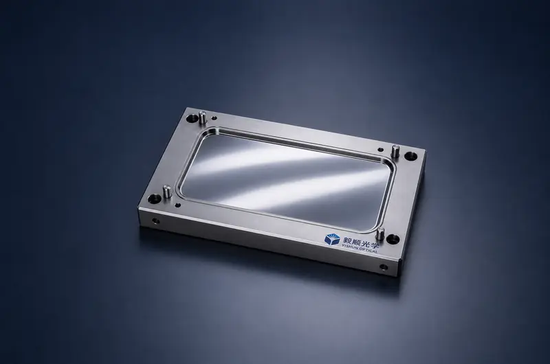
Phone Housing Insert Configurations We Can Support
Broad Rear-Cover A-Surface
Large mirror or high-gloss areas where form, reflected-line continuity, and local surface defects are the main concerns.
Curved Perimeter Insert
Housing inserts that combine a broad face with curved edges, side walls, borders, transition radii, or freeform areas.
Feature-Dense Housing Insert
Designs containing ports, speaker slots, side-key openings, narrow grooves, corners, and parting-line features within the agreed scope.
Gloss-to-Texture Boundary
Mirror areas next to a customer-defined textured zone. We control the transition geometry; texture generation requires separate confirmation.
Prototype or Replacement Core
One trial insert, one new core, or a replacement that must match an existing cavity and datum system.
Matched Multi-Cavity Inserts
Insert sets that require common references and agreed comparison items for form, gloss, edges, and position.
Common Phone Housing Mirror Insert Problems and Our Solutions
Ra Meets the Target, but Reflected Lines Still Look Wavy
Surface roughness describes small-scale texture; it does not describe the complete form of a broad phone-housing surface. An insert can have a low Ra value and still show local waviness or curvature error.
Our approach: We connect the roughness requirement with profile, form, and reflected-line acceptance. The drawing should identify the visible area and where form or profile must be checked.
Periodic Tool Marks Appear After Molding or Decoration
Periodic marks may be difficult to notice on the metal insert under ordinary light, but replication or a reflective finish can make them stand out on the phone shell.
Our approach: We agree on inspection locations, viewing conditions, allowed directional marks, and local-defect limits before machining. Surface quality is not approved by brightness alone.
The Curved Perimeter Loses Reflection Continuity
A broad face may be acceptable while the transition into a side wall or corner shows a visible break. Tangency, local form, and transition radii all affect this area.
Our approach: We review the CAD continuity and the critical transition profiles, then keep the broad face and curved perimeter within one coordinated acceptance plan.
Ports, Steps, or Outer Edges Become Soft
Small openings and sharp transitions can lose definition when their radius, depth, access, and relationship to the mirror surface are not considered separately.
Our approach: We separate geometry-critical features from the broad appearance surface. The smallest radius, edge condition, and feature position are confirmed before we select the route.
The Surface Looks Right, but the Housing Does Not Assemble Correctly
The visible face can pass its own surface check while a locating feature, frame interface, or port position is offset. The result may be uneven gaps or poor visual alignment.
Our approach: We keep the appearance surface tied to the approved mechanical datums. Critical locating and matching features remain part of the same dimensional plan.
How We Define the Machining and Acceptance Scope
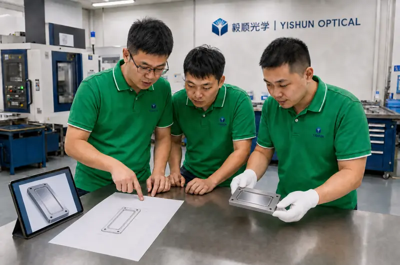
We begin with the drawing, 3D model, material, hardness, and the customer’s actual problem. Then we divide the insert into the broad appearance surface, curved transitions, edges and openings, locating datums, and non-critical areas. Each zone receives a clear control item rather than one general “mirror finish” note.
For example, the main A-surface may require form and roughness control, while an opening may require position, radius, and edge-definition control. A replacement insert may need comparison with an existing cavity. Once these requirements are clear, we can choose a practical route and quote against a defined technical scope.
How Yishun Supports Your Project
Risks Identified Before Machining
We point out unclear appearance zones, missing radii, conflicting datums, inaccessible features, and inspection gaps before they become rework.
Measurable Approval Criteria
Form, roughness, local defects, feature geometry, and visual conditions are assigned to appropriate checks instead of one vague surface note.
Appearance and Fit Reviewed Together
The mirror face is not separated from the edges, openings, and datums that determine how the housing aligns and assembles.
Practical Replacement Matching
Support for Replacements and Sets
Common references make it easier to evaluate one replacement core or compare several cavities of the same housing design.
Inspection for Appearance-Critical Inserts
Inspection is selected according to the characteristic being controlled. CMM measurement can verify dimensions and datum relationships. Roughness measurement evaluates micro-surface texture. White-light interferometry, microscopy, optical scanning, or profile comparison may be used for suitable surface, form, and local-defect checks.
Visual appearance requires its own definition. If reflected-line continuity, directional marks, gloss variation, or small defects matter, please provide the lighting, viewing angle, viewing distance, defect limit, or approved sample used by your team. We confirm the inspection locations and report coverage before machining so the result can be judged against the same standard.
Information Needed for a Technical Review
Please send the 2D drawing, 3D model, insert material and hardness, marked appearance zone, smallest radius, critical dimensions, datum scheme, target roughness, visual standard, cavity quantity, and inspection requirement. If you are solving an existing defect, add clear photos and explain when it appears: on the insert, after molding, or after decorative finishing. That distinction helps us focus on the correct cause.
FAQ
Do you manufacture complete mobile phone housing molds?
No. Our focus is precision machining of the critical mirror insert or mold core. Send the exact insert scope, and we will confirm whether it matches our service.
Which insert materials can you machine?
We review customer-specified mold steels, aluminum alloys, copper alloys, and plated substrates. Feasibility depends on the grade, hardness, geometry, surface target, and previous treatment.
Can the mirror finish be machined directly?
Yes, when the material, geometry, access, and surface requirement are suitable. The actual process route is confirmed after drawing and material review.
Can you guarantee ±0.001 mm and Ra 0.005 μm on every insert?
No. These values come from selected phone and consumer-electronics mirror-mold cases. Each project must be evaluated against its own size, geometry, material, tolerance, and measurement method.
Can you machine a mirror area next to a textured area?
We can review the transition geometry and protect the boundary within the agreed scope. Generation of the textured surface itself requires separate confirmation.
Can you make one prototype or replacement core?
Yes. A single trial or replacement can be reviewed. For a replacement, please provide the original data and explain which appearance and datum features must match the existing cavity.
What if the finished shell still shows a defect?
Send photos and tell us when the defect first appears. We will help distinguish likely insert-related issues from molding, shrinkage, resin, or decorative-process effects before discussing corrective work.
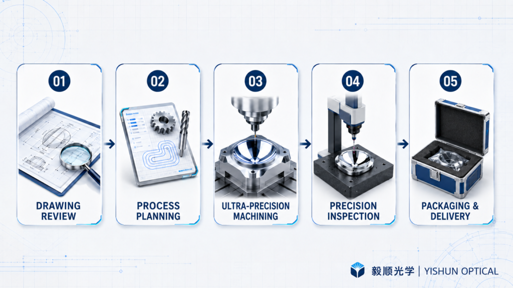
Inspection and Order Process
Inspection may cover dimensions, datums, profile, form deviation, roughness, periodic marks, local defects, edge condition, transition geometry, and cavity comparison. Before machining, we agree on what will be measured, where it will be measured, and how appearance will be judged.
For an efficient quotation, please send the 2D drawing, 3D model, insert material and hardness, appearance-zone definition, smallest radius, critical dimensions, target roughness, visual standard, cavity quantity, matching requirement, inspection method, current defect, and delivery target.
Let’s Review Your Mobile Phone Housing Mirror Insert
If your current insert shows waviness, periodic marks, softened edges, datum mismatch, or cavity variation, send us the drawing and explain what you see on the finished housing.
We will review the geometry, material, appearance zones, matching requirement, and inspection basis before proposing a practical route for mobile phone housing mirror mold insert machining.