
Custom Machining for Automotive Headlamp Reflector Mold Inserts
Reflector mold work becomes risky when freeform geometry, mirror finish and cavity boundaries stop matching each other.
YISHUN provides custom machining for automotive headlamp reflector molds and inserts by planning the route around the optical surface first, then controlling geometry, finishing and inspection as one linked job.
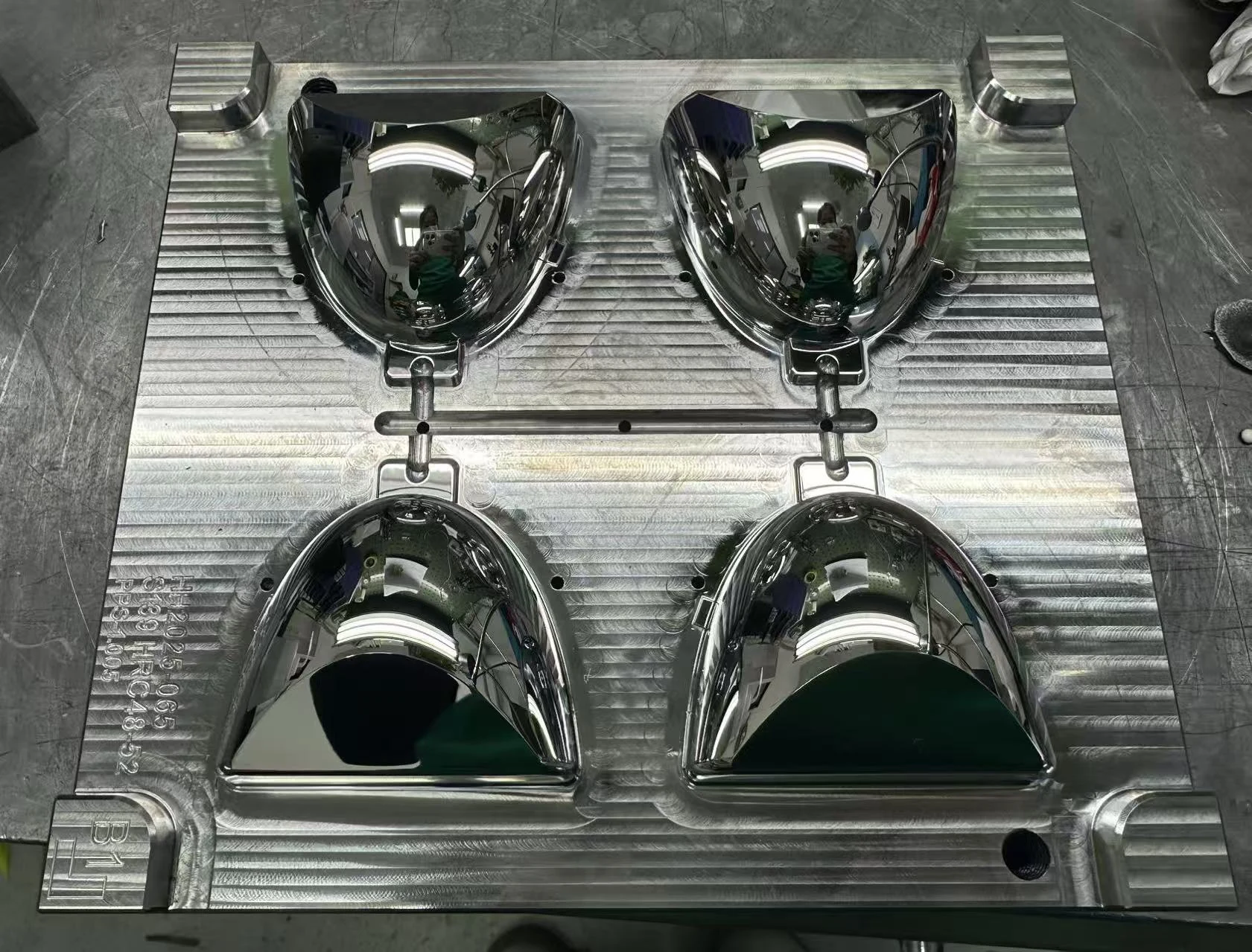
We do not confirm a reflector machining route from the machine list alone.
The drawing, optical zones, datum scheme, cavity depth, finishing allowance and inspection method are reviewed together before material is removed.
If a surface will be difficult to correct later, that risk should be identified at the review stage鈥攏ot after the reflector cavity has already been cut.
Identify the surfaces that cannot be treated like ordinary mold steel.
Freeform areas, steep transitions, local features and protected boundaries are reviewed before the tool path is fixed.
Keep machining and inspection tied to the same reference logic.
Datum stability and clamping strategy are checked early, especially for matched inserts and correction work.
Decide what should be cut to final geometry and what can be refined safely.
Mirror finishing is planned with clear limits so surface improvement does not soften critical optical geometry.
Define how the result will be judged before another cut is approved.
Form, surface condition, reflection continuity and the agreed inspection method guide correction decisions.
The goal is not only a mirror-bright insert. It is fewer avoidable corrections and better control of the reflector surface.
For purchasing and engineering teams, the value is practical: protect the optical geometry, reduce late-stage rework and make the machining result easier to evaluate against the agreed project requirements.
What you gain from a controlled reflector machining route.
We connect drawing review, machining, finishing and inspection so that each step supports the same optical requirement. That gives the project a clearer path from the first cut to final acceptance.
Previously handled automotive optical mold work provides a practical reference for new reflector projects.
YISHUN has documented automotive optical mold mirror-machining work. The figures below show a previous project reference for handled size, accuracy and mirror-surface capability before a new reflector insert is reviewed.
These figures are previous project references rather than universal tolerances. Final achievable results are reviewed according to geometry, material, optical area and the agreed measurement method.
We look for the cause before recommending another cut or polishing pass.
The quickest correction is not always the safest correction. For optical reflector surfaces, removing more material before understanding the deviation can make the geometry harder to recover.
Our response: review local form deviation, tool-path periodicity and finishing history before deciding whether correction belongs in machining or finishing. This helps avoid polishing a geometry problem and creating another correction cycle.
Our response: identify whether the signature comes from cutting direction, pitch, vibration or a finishing step that did not remove the root error. Correcting the source is safer than repeatedly polishing the same visible line.
Our response: define protected zones and reduce uncontrolled finishing where the local transition must remain geometrically sharp. The objective is to improve the mirror area without rounding the boundary the reflector depends on.
Our response: review datum strategy, clamping, stock allowance and machining sequence across the complete insert set. This gives the project a better basis for reducing visible cavity-to-cavity variation.
How we think about acceptance
The hardest part is not making the cavity shiny. It is keeping geometry, finish and repeatability under control at the same time.
Automotive headlamp reflector mold inserts combine broad freeform optical areas, deep cavities, local transitions and mirror requirements. A process that improves one surface condition can create another geometry problem if the whole insert is not reviewed as one system.
Complex form changes across one cavity
Local curvature, steep walls and changing tool contact make one fixed cutting strategy unreliable across the complete reflector surface. Reviewing these changes before cutting helps reduce local form correction later in the project.
Tool access changes with depth
Deep reflector areas can restrict tool orientation and create risk around surface continuity, local marks and structural interference. Planning access early helps reduce the chance of discovering directional tool marks only after final finishing.
A bright surface can still be wrong
Low Ra does not automatically remove waviness, periodic signatures or local form errors that become visible in reflection. The goal is to avoid a surface that looks polished but still fails the functional reflection requirement.
Matched inserts must behave alike
Datum, clamping, stock allowance and finishing sequence all affect whether several reflector inserts remain comparable. Controlling the route as one set reduces avoidable cavity-to-cavity variation.
Reflector mold inserts are reviewed by optical geometry, cavity depth and machining risk.
We support custom machining of automotive reflector mold cores / inserts based on customer-approved 2D drawings, 3D surface data, material, critical optical zones and acceptance requirements.
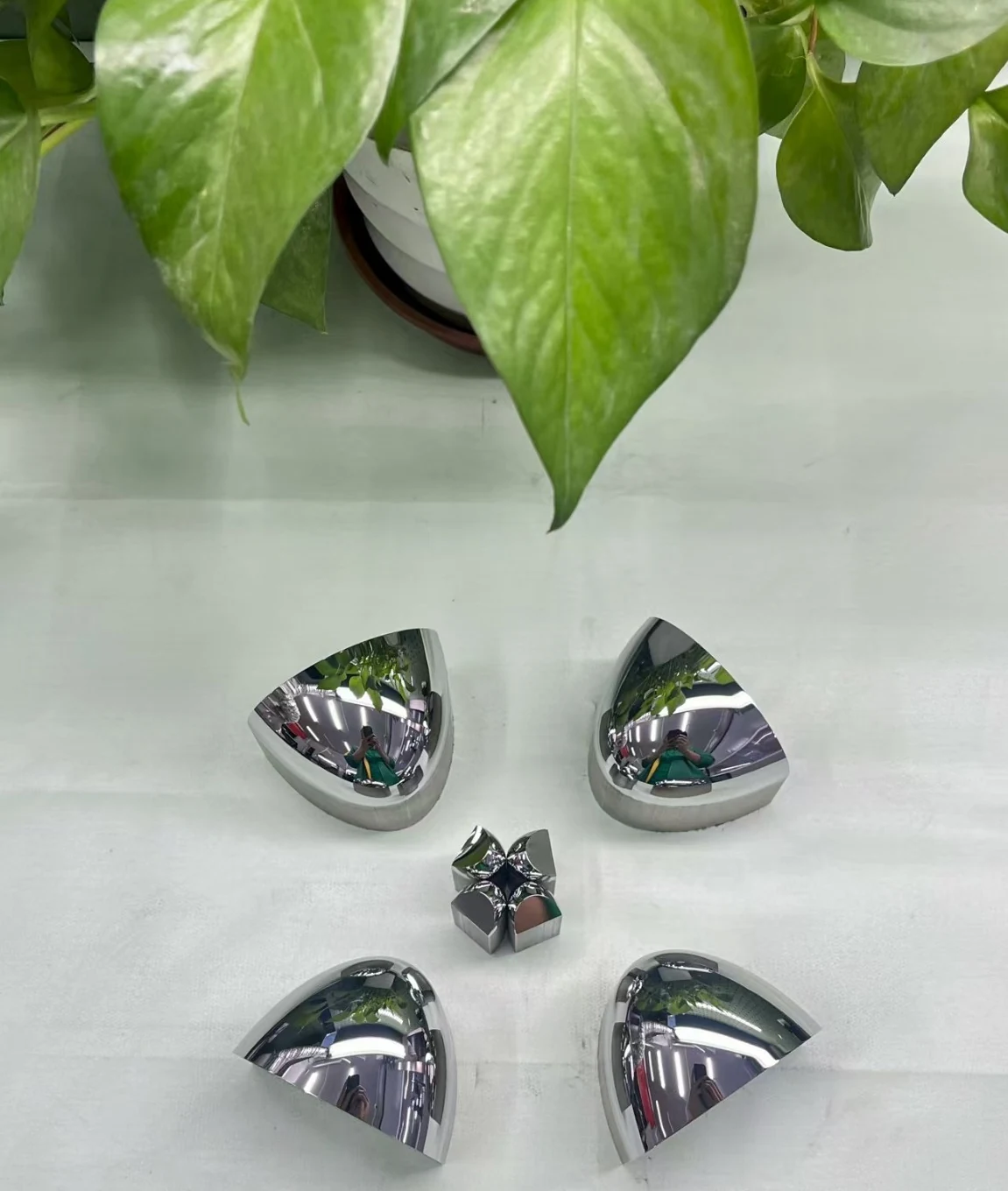
Freeform & deep reflector mold inserts
Machining route is planned around the optical surface, steep local geometry, access and protected transition areas.
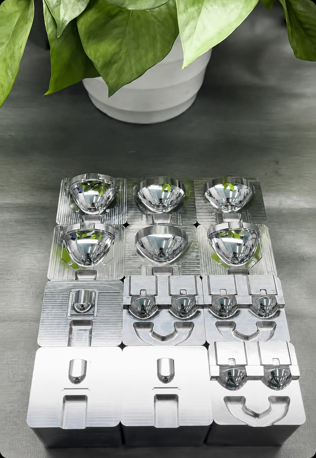
Consistency across several reflector inserts
Datum, clamping and machining sequence are reviewed across the set rather than one cavity at a time.

Optical surfaces with local features & boundaries
Critical mirror areas, structural features and local transitions are controlled within one machining plan.
This is most relevant when the reflector insert is already difficult to machine, finish or correct without creating another optical-surface risk.
The projects below are where process judgement usually matters more than simply adding another machining or polishing pass.
If one of these conditions matches your project, the first step is to review the drawing, current defect information and acceptance method before deciding the machining route.
Ra can pass while the reflector still shows an unstable reflected line.
For reflector mold work, we do not evaluate mirror quality from Ra alone. Surface form, waviness, tool-path signature, transitions and the agreed inspection method must be considered together.
Six decisions are made before final machining and finishing are fixed.
Identify the most sensitive surface zones
Freeform data, local curvature and stock condition are reviewed before the tool path is finalized. This helps prevent correction effort from being spent on the wrong surface zone later.
Plan around cavity depth and cutting direction
Tool orientation, interference risk and directional cutting signatures are considered before machining begins. The aim is to reduce late-stage tool marks that are difficult to remove without affecting form.
Protect optical edges and transitions
Local boundaries are defined so finishing does not soften geometry that the reflector surface depends on. This protects critical transitions while mirror quality is improved.
Decide what should be cut to final and what should be refined
Polishing is used only where appropriate and is not relied on to rebuild the final freeform geometry. This reduces the risk of gaining gloss while losing the intended optical form.
Keep machining and inspection references consistent
Reference stability becomes especially important for matched inserts, correction work and replacement projects. Keeping one datum logic helps reduce mismatch between machining, inspection and assembly references.
Use inspection before approving another material-removal step
When correction is needed, measured deviation and surface condition are reviewed before another cut or finishing pass. This helps avoid unnecessary material removal and repeated correction cycles.
Machines build capability only when the process around them is controlled.
This section shows three different parts of the execution system: operator-controlled ultra-precision machining, controlled optical finishing support, and dedicated machining capacity for precision mold work.
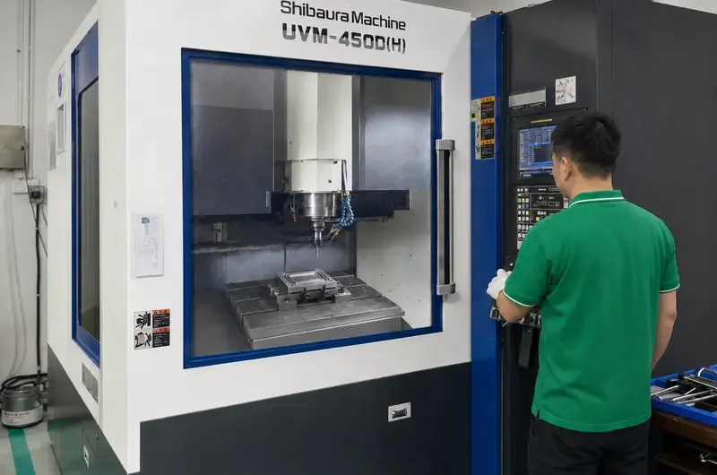
Shibaura UVM-450D(H) machining
A YISHUN technician operating the Shibaura ultra-precision machining system, showing the machining and setup capability used across precision optical mold projects.
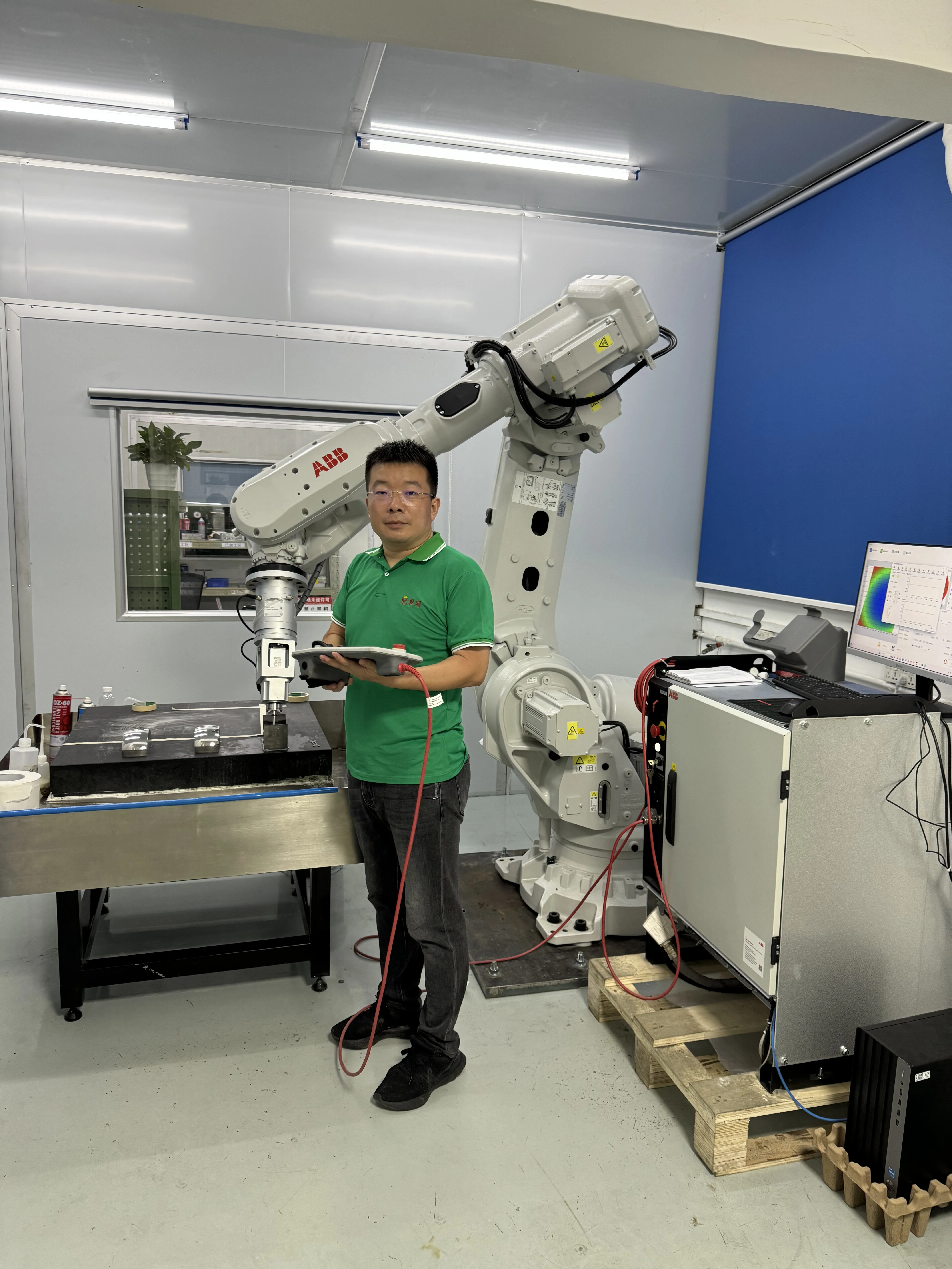
Six-axis optical polishing support
YISHUN technician working with the ABB six-axis system used for controlled optical finishing support when the project route requires it.
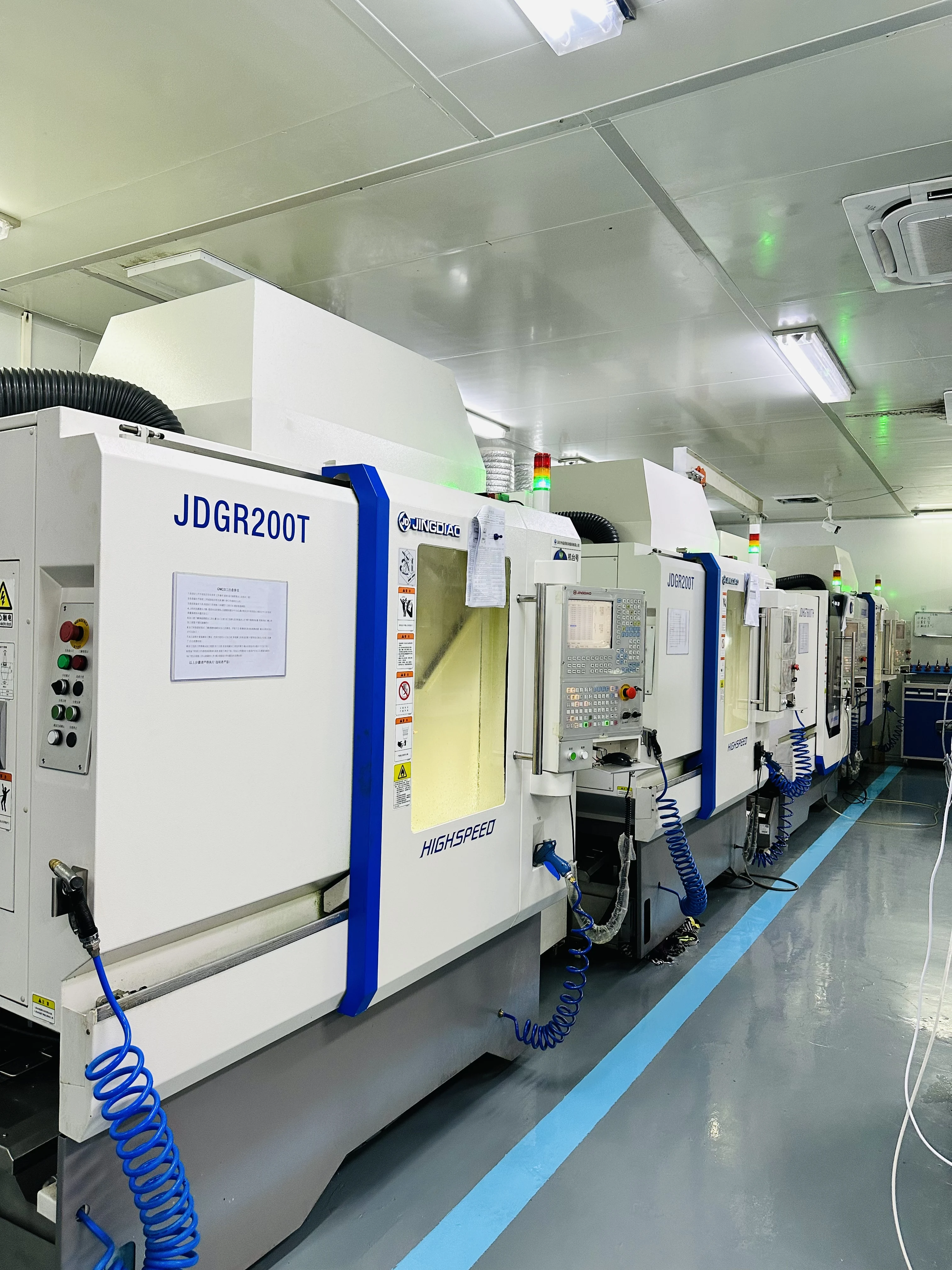
JINGDIAO JDGR200T machining capacity
A dedicated line of JINGDIAO precision machining systems supporting capacity, repeatability and stable execution across precision mold projects.
Send the information that defines the reflector surface, the acceptance target and the machining risk.
For automotive headlamp reflector mold insert custom machining, the first useful question is not only 鈥淐an you machine this shape?鈥?We need enough project information to decide how the optical area should be held, cut, finished and inspected.
Project boundary
YISHUN focuses on custom machining and controlled finishing of precision optical mold cores / inserts according to customer-approved project data. Headlamp optical-system design, final injection molding and complete mold-build responsibility remain outside this page unless separately confirmed for a specific project.
One controlled route from drawing review to inspection feedback.
The process is adjusted to the actual reflector geometry and project requirements. The sequence below shows how we reduce risk before, during and after machining.
Drawing & surface review
Confirm optical areas, geometry, material, datum, surface requirement and inspection scope.
Machining strategy
Define fixturing, stock, tool access, cutting direction and protected transition areas.
Precision machining
Apply the suitable five-axis or ultra-precision route for the approved geometry and material.
Controlled finishing
Improve mirror quality only where the process can protect the intended optical form.
Inspection
Check agreed dimensions, datum relationships, surface condition and project-specific geometry.
Correction & release
Use inspection feedback to decide whether correction is needed before another removal step is approved.
Automotive headlamp reflector mold insert custom machining questions
Freeform reflector surfaces can be evaluated from the 3D model, local curvature, cavity depth, mold material, datum structure, tool access and the required inspection method. We confirm the route after engineering review rather than applying one fixed process to every insert.
We start from the critical optical surface and project risk. Machining, finishing and inspection are planned together so that improving surface gloss does not create avoidable form, boundary or datum problems.
No. Roughness is only one acceptance dimension. Form error, waviness, periodic tool marks and softened transitions can still affect visible reflection even when Ra is low.
No. The goal is to preserve the intended geometry through the machining route and use controlled finishing only where appropriate. Polishing should not be used to recreate the final freeform shape after machining.
Yes, these projects can be reviewed. Datum strategy, current geometry, remaining stock, machining sequence and the customer's consistency criteria should be defined before material is removed.
No. Those values come from a documented automotive optical project reference and are not universal guarantees. Achievable results depend on geometry, material, optical area, access and the agreed measurement method.
Have a reflector mold that is difficult to machine without losing the optical surface?
Send us your 2D drawing, 3D model, mold material and optical requirements. Our team will review the reflector geometry, machining risk, mirror-surface requirements and inspection method before recommending a machining route.