
Automotive Headlamp Lens Mold Solution
For headlamp lens inserts with freeform, aspheric or multi-cavity optical surfaces, geometry and mirror quality need to be controlled together—not corrected by polishing after the form has already drifted.
YISHUN machines custom optical mold cores and inserts from customer-approved drawings, 3D data, material requirements and agreed inspection criteria. Our scope focuses on the precision mold insert—not complete mold building or injection molding.
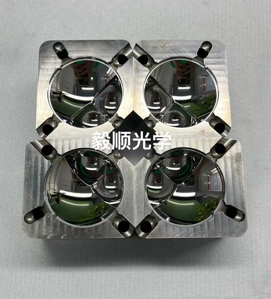
A low Ra value is not enough for a headlamp lens mold.
A surface can look bright and still produce optical or assembly problems when the form, transition, edge or cavity relationship changes during machining or finishing.
Polishing changes the form
Removing tool marks by hand can soften local curvature or change a freeform/aspheric surface that was already close to the drawing.
Transitions lose definition
Optical-to-structural transitions, local edges and neighboring features can become rounded or blended when the finishing route is not planned early.
Cavities no longer match
Multi-cavity lens inserts need more than one good cavity. Datum stability and a repeatable machining sequence are required across the set.
Surface looks fine, reflection does not
Periodic tool marks, waviness or local form error can remain visible in reflection even when the roughness number alone appears acceptable.
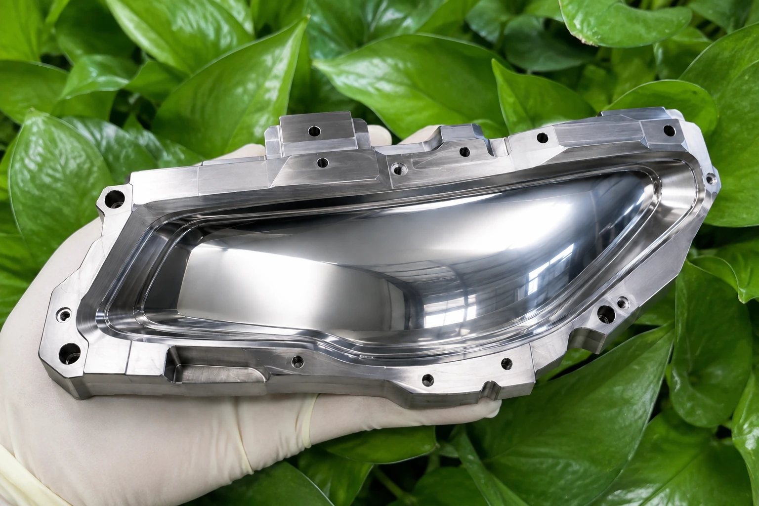
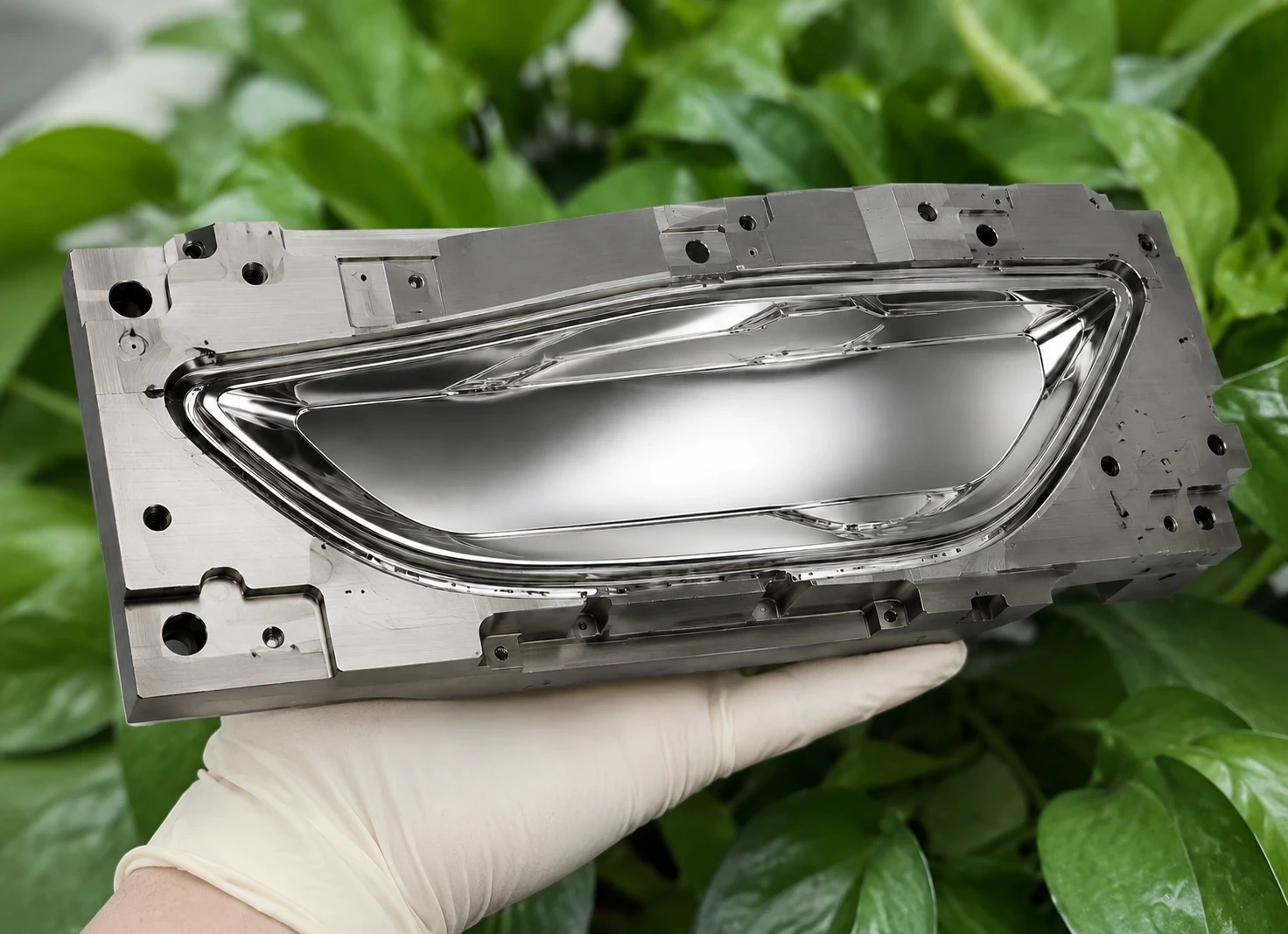
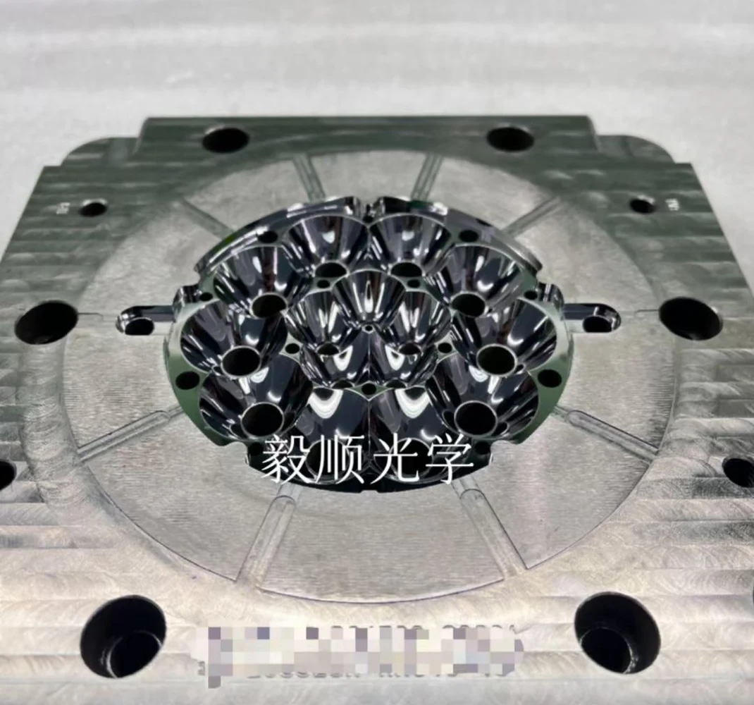
We evaluate the insert around the optical surface—not around a generic CNC process.
The final route depends on geometry, mold material, tool access, edge conditions, surface requirement and how the customer plans to inspect the optical area.
Four areas we review before machining starts.
These checks are intended to reduce the risk of solving one surface problem while creating another geometry problem.
Surface geometry
Freeform/aspheric data, local curvature and stock condition are reviewed before the final tool path and finishing route are fixed.
Edges & boundaries
Optical-to-structural transitions are protected so that finishing does not soften the geometry that the drawing depends on.
Reference stability
Machining and inspection references need to stay consistent, especially when several cavities or replacement inserts must match.
Mirror quality
Surface finish is evaluated together with tool marks, reflection continuity and the agreed form requirement—not as a standalone Ra target.
Use project data as a reference, not a blanket promise.
Headlamp lens molds vary widely in size, curvature, optical area and inspection method. We therefore confirm the acceptance range after drawing review.
Documented automotive optical project reference
YISHUN company materials record automotive lamp pattern and lens mold mirror machining work with the following project values.
We choose the route after the optical surface and risk areas are understood.
Drawing & model review
Confirm the optical zone, datum, critical dimensions, cavity relationship, material condition and inspection expectations.
Process planning
Decide how to leave stock, where finishing is allowed, and which transitions or edges must remain protected.
Precision machining
Use the suitable high-speed five-axis or ultra-precision route for the actual geometry and material.
Controlled finishing
Apply mirror finishing only where needed and only within a route that protects the required geometry.
Inspection
Check the agreed dimensions, reference features, surface condition and project-specific optical geometry requirements.
Correction & release
If correction is required, review the measured deviation before another cutting or polishing pass is approved.
Real project data should explain our capability more clearly than a generic tolerance table.
YISHUN’s company materials document automotive lighting work including lamp pattern and lens mold mirror machining. The project reference below is used only to show the scale and precision level already handled in automotive optics.
Equipment supports the process; the review logic decides how it is used.
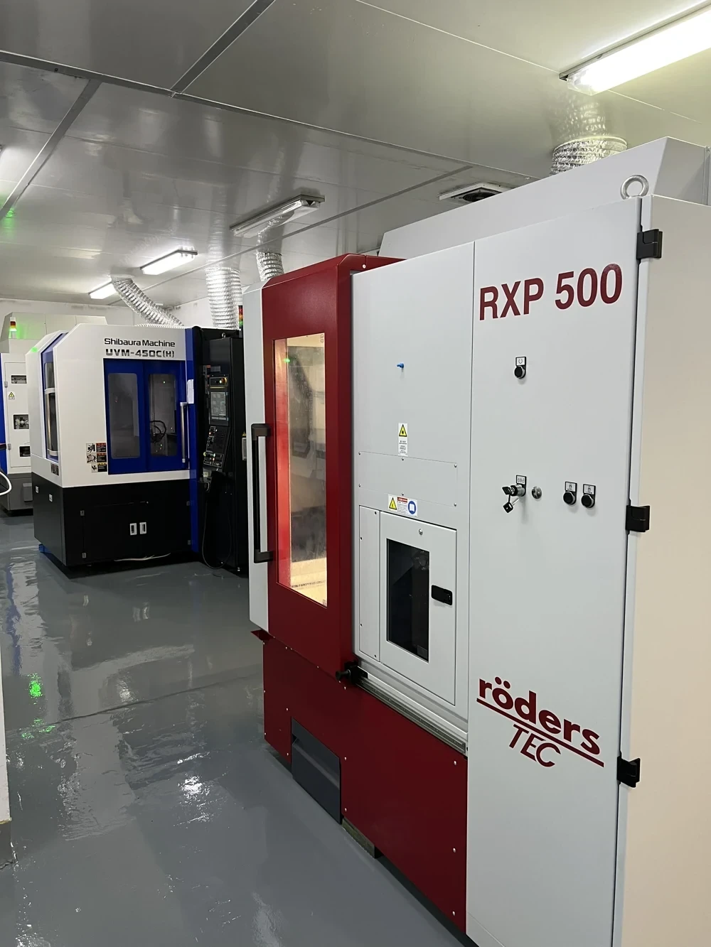
Röders precision machining
Used within YISHUN’s high-precision machining workflow for complex optical mold geometry.
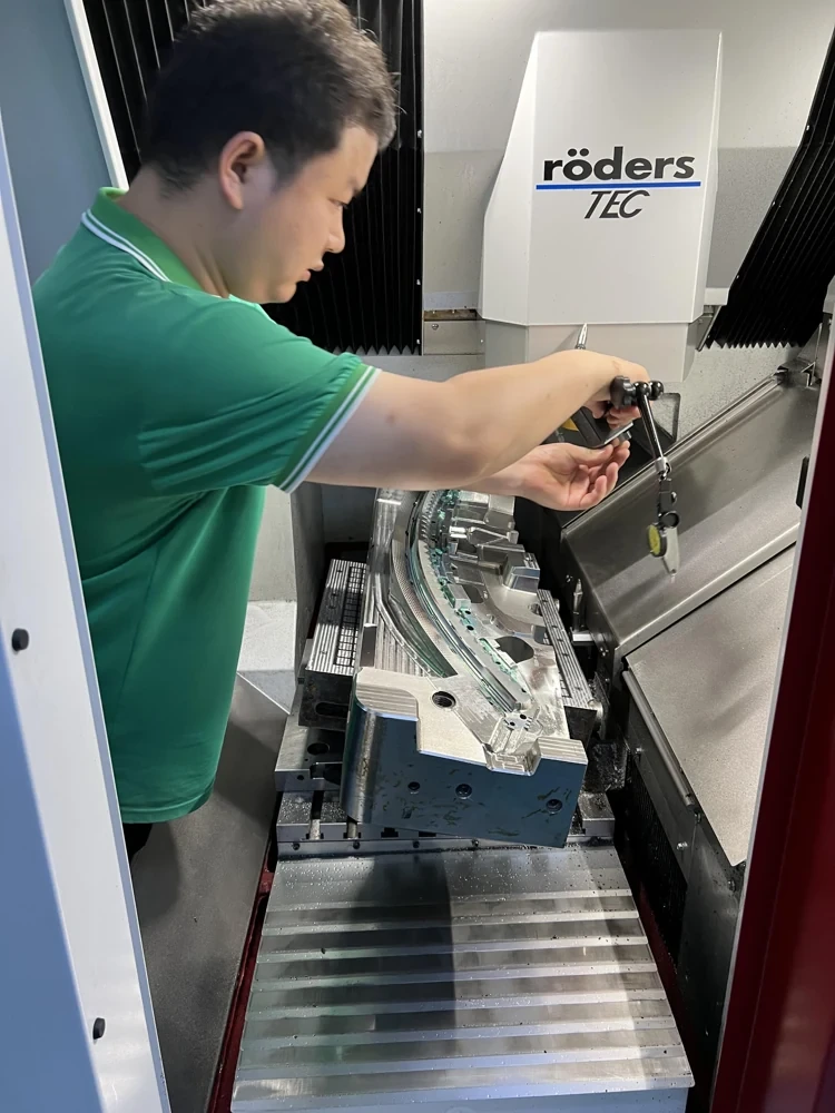
Automotive optical machining case
Real company-project image showing precision machining work used for automotive optical mold applications.
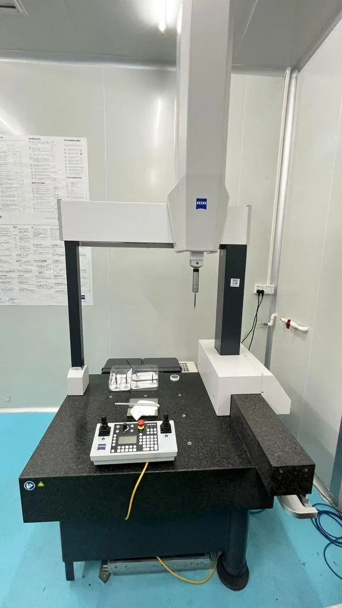
ZEISS CMM inspection
Reference features and dimensional relationships can be checked according to the agreed inspection plan.
Send the information that defines the optical surface and the risk.
A useful review is not just “Can you machine this shape?” We need enough project information to decide how the optical zone should be held, cut, finished and measured.
Project boundary
YISHUN focuses on machining and finishing the precision optical mold core / insert according to customer-approved project data. The headlamp optical system design, final injection molding and complete mold-build responsibility remain outside this page unless separately confirmed for a specific project.
Automotive headlamp lens mold questions
Yes, these geometries can be evaluated from the 3D surface, material, local curvature, tool access and required inspection method. We confirm the feasible machining route after review rather than applying one fixed process to every lens mold.
Multi-cavity work can be evaluated. The review focuses on cavity matching, datum strategy, machining sequence and how the customer plans to verify consistency across the set.
No. Ra 0.005 μm is a documented reference from an automotive optical project, not a universal guarantee. Geometry, material, optical zone, accessibility and inspection method all affect the final achievable result.
No. The target is to preserve the required geometry through the machining route and use controlled finishing only where appropriate. Polishing should not be used to “discover” the final shape after machining.
We can review replacement or correction work when the current geometry, remaining stock, reference features and measured deviation are available. We do not recommend removing more material before the cause and correction direction are understood.
Start with the 2D drawing, 3D model, mold material, marked optical surface, surface/form requirements, cavity quantity and any existing defect or inspection information.
Have a headlamp lens insert that is difficult to machine without losing the optical form?
Send the drawing, 3D model and acceptance requirements. We will review the optical zone, geometry risk, finishing boundary and inspection route before recommending a machining plan.