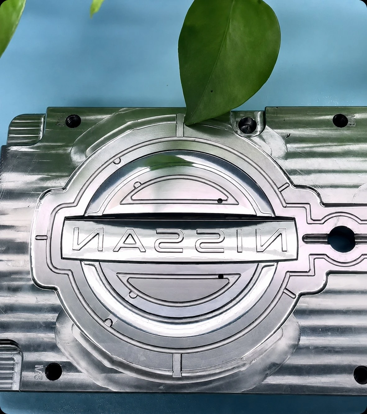
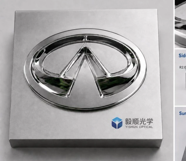
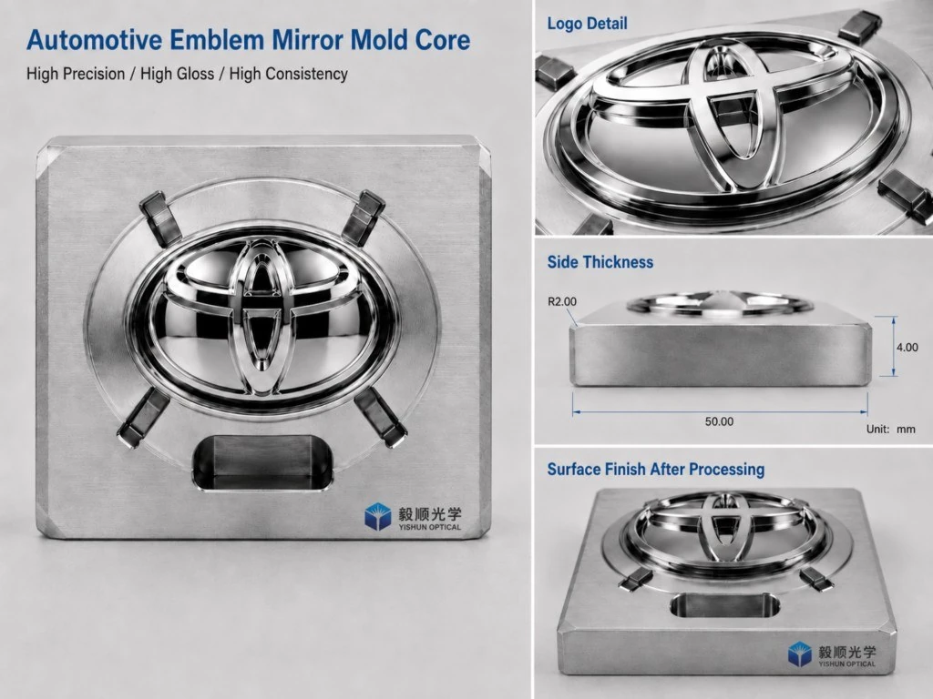
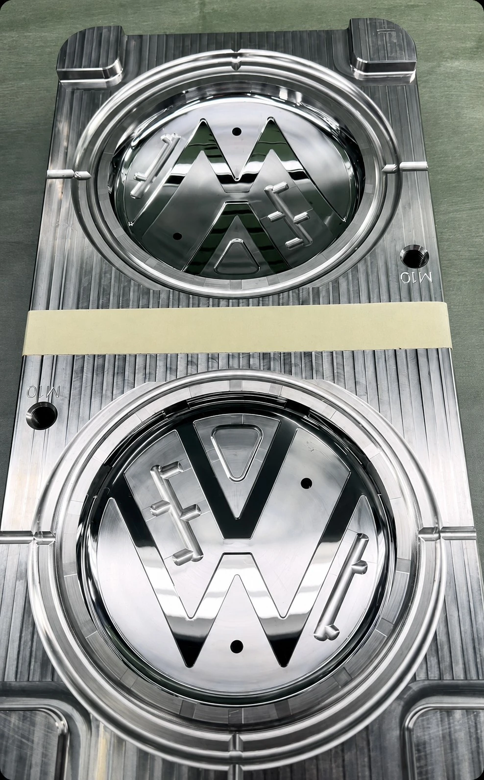
If you are developing a chrome-plated, high-gloss black, transparent, or illuminated automotive emblem, the hardest part is usually not simply making the surface shiny. Small tool marks and surface waviness can transfer to the molded part and become more visible after chrome plating, painting, or PVD. At the same time, polishing can soften logo edges. This often leads to repeated trial molding and rework.
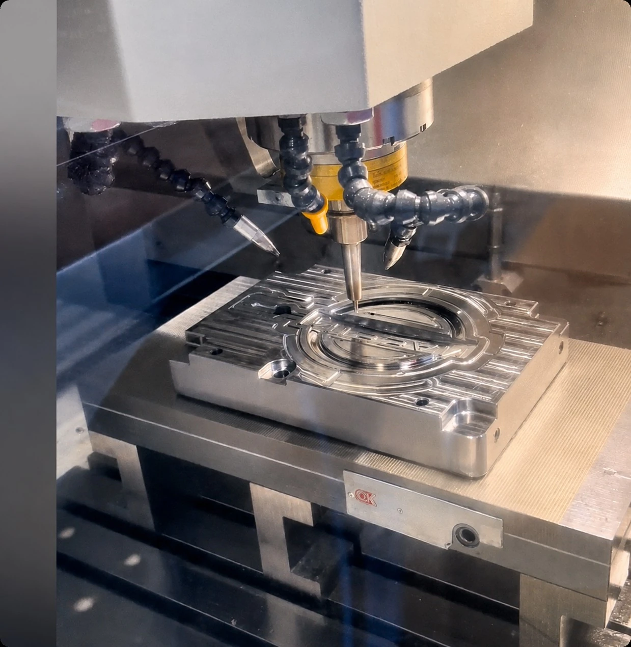
We focus on high-precision mold cores and inserts. Based on your 2D drawings, 3D models, and surface requirements, we machine high-gloss emblem cores, mirror-finish inserts, decorative-texture inserts, and replacement inserts. We do not sell standard stock parts. For each project, we first review the drawing, material, and downstream surface treatment before we define the machining plan.
Automotive emblems sit where customers can easily see them. Uneven gloss, soft logo lines, fine scratches, or different reflections between matching parts can lower the visual quality of the vehicle. Once the mold surface is copied to the part and covered by a reflective finish, a small machining or polishing defect can become a production problem. We therefore look at the complete process, not only the insert before shipment.
Automotive Emblem Projects We Can Support
Different emblem designs need different machining strategies. A large curved badge has different risks from a set of small letters, and a transparent illuminated emblem has different surface needs from a painted or chrome-plated part. We review each project as a custom insert-machining job.
- Front-grille emblems, rear emblems, steering-wheel emblems, and wheel center-cap emblems
- Brand logos, letter emblems, model names, and fine decorative lines
- Mold cores for chrome-plated, electroplated, PVD-coated, painted, or high-gloss black parts
- Covers, light-guide features, and key appearance inserts for transparent or illuminated emblems
- Single-cavity, multi-cavity, complete letter-emblem sets, and individual replacement inserts
The final machining range depends on the mold material, feature depth, tool access, surface standard, and inspection method.

-1024x768.png)
Three Common Pain Points in Automotive Emblem Mold Insert Machining
1. Surface Treatments Make Small Defects More Visible
Chrome plating, vacuum coating, and high-gloss paint do not hide tool marks, fine scratches, orange peel, or local waviness transferred from the mold surface. They can make these defects easier to see. We first confirm the molding resin, the later surface treatment, and the Class A visible surfaces. Then we define which areas need the highest mirror quality. We do not judge the result by brightness alone.
A defect may look small on the steel insert but appear much stronger on the finished emblem. A tool mark can become a bright line. Local waviness can change the reflection at different viewing angles, while orange peel can make a high-gloss surface look cloudy. If these problems are found only after molding and surface treatment, the customer may need another trial, another polishing cycle, or a replacement insert. We reduce this risk by linking the final appearance back to the mold surface before machining starts.
2. A Bright Surface Can Still Lose Logo Detail
Small letters, narrow grooves, small radii, and height changes can easily become rounded during polishing. We separate the areas that need a mirror finish from the areas that must keep their original shape. We control tool access, polishing allowance, contact area, and material removal. The goal is to balance surface quality with clear and accurate logo geometry.
Over-polishing creates a common trade-off: the surface becomes brighter, but the design becomes weaker. Letter edges can lose sharpness, narrow grooves can become shallow, and the transition between high and low areas can change. These changes may affect brand recognition, part fit, or the way light moves across an illuminated emblem.
For complex logos, we do not use the same polishing pressure and contact method in every area. We plan local finishing around the geometry. This controlled approach is especially important near small radii, steep walls, fine decorative lines, and areas where a polishing tool has limited access.
3. One Good Insert Does Not Mean the Full Set Will Match
For multi-cavity tools, left-and-right sets, or full letter-emblem sets, we must compare datums, critical dimensions, logo profiles, edge condition, and the reflected appearance of curved surfaces. Even if each insert passes a basic size check, visible differences may still appear when the parts are placed on the same vehicle. We therefore check insert-to-insert consistency against the standards agreed with the customer.
Consistency is not only a dimensional issue. Two inserts can both be within tolerance but still produce different gloss or reflection because their surface conditions are not the same. This can be seen in left-and-right emblems, complete model-name sets, or several cavities running in one program.
The customer may then face sorting, matching, or higher cosmetic scrap. To avoid this, we use the same process references across the set, compare important surfaces, and keep the machining and polishing route as stable as possible. The inspection plan should also define which features must be compared between inserts, not only which features must pass on each single insert.
What We Confirm Before Machining
A clear technical agreement at the beginning can prevent many later changes. Before machining, we normally ask the customer to confirm the following points:
- Critical visible surfaces: Which areas are Class A surfaces, which areas can accept normal machining marks, and which edges or logo features must not be rounded.
- Downstream process: The molding resin and whether the final part will be chrome plated, painted, PVD coated, vacuum coated, transparent, or illuminated.
- Acceptance method: The required SPI grade or Ra value, any approved appearance sample, the viewing condition, and the agreed measurement method.
- Set consistency: Whether the project includes multiple cavities, matching left-and-right parts, or a complete letter set that must have the same visual result.
If some of this information is not available, we can still begin with the 3D file, part photos, and defect photos. We will identify the missing points and explain which ones can change the machining result.
How We Handle Your Project
- Drawing review: We review the 2D and 3D files, mold material, critical tolerances, visible surfaces, later surface treatment, and any current defects. We also check depth, wall angle, small radii, narrow grooves, and tool-access limits. This helps us find the highest-risk areas before material is removed.
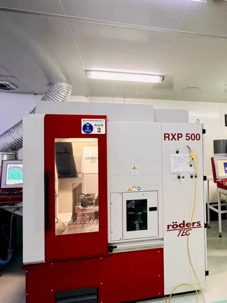
- Process planning: Based on the geometry, we select five-axis precision machining, five-axis mirror machining, precision grinding, controlled mirror polishing, or a combined route. We define datums, tool paths, finishing order, and the correct finishing allowance. Different areas may use different processes because the surface and geometry risks are not the same.
- Machining and detail protection: During machining and polishing, we control the amount of material removed around complex curves, logo edges, fine grooves, and small radii. We keep the finishing contact local where needed and avoid unnecessary polishing on geometry-critical areas. This prevents a bright finish from damaging the required shape.
- Inspection and result check: We use a coordinate measuring machine (CMM), roughness tester, and measuring microscope. Results are checked against the drawing and surface standard. For insert sets, we compare common features. Acceptance and record scope are confirmed before machining.
Protecting Mirror Quality without Losing Geometry
Mirror quality and geometric accuracy must be controlled together. If we only chase a low Ra value, we may remove too much material from an edge or a small feature. If we only protect geometry, the surface may keep tool marks that later appear on the finished emblem.
Our process therefore separates surface-critical zones from geometry-critical zones. We choose the tool, polishing contact, direction, and removal amount for each type of area.
We also pay attention to transitions. A logo often contains flat areas, curved areas, steep walls, and narrow lines in one small insert. The reflected appearance can change at each transition. A controlled transition is often more important than making one local area extremely bright. This is one reason drawing review and local finishing plans are necessary for complex automotive emblem inserts.
Technical Capability Must Be Confirmed after Drawing Review
For suitable materials, sizes, and geometries, dimensional or contour accuracy can be evaluated to ±0.005 mm, and surface roughness can be evaluated to Ra 0.008 μm. Mirror-finish requirements can be agreed by SPI A-1, a specified Ra value, an approved appearance sample, and a defined measurement method.
These values are not a general promise for every drawing. Deep cavities, narrow grooves, small letters, sharp corners, small radii, complex freeform surfaces, and areas with poor tool access can all limit the final result. We prefer to review the 3D file and give you a clear answer instead of applying one number to every project.
The measurement method must also match the requirement. Dimensional accuracy, contour accuracy, surface roughness, edge condition, and visual reflection are different items. One number cannot describe all of them.
For this reason, we confirm the inspection item and method before production. This makes the final result easier for both sides to understand and reduces disagreements caused by different measurement conditions.


Why Customers Trust Us with Difficult Projects
We connect five-axis mirror machining, ultra-precision machining, controlled polishing, and inspection in one working process. At the same time, we protect surface quality, dimensional accuracy, and fine geometry.
For you, this means less rework, a smoother downstream surface-treatment process, and a more stable appearance from samples to repeat production.
Our value is most clear when the project has a difficult curve, a tight cosmetic standard, small logo details, or a consistency problem that a normal polishing process cannot solve. We do not begin with a fixed process list. We begin with the failure risk and build the process around the actual drawing.
FAQ
Can you achieve SPI A-1 or Ra 0.008 μm?
We can evaluate these requirements for a specific project. First, we need to confirm the material, curved-surface geometry, depth, feature size, and measurement method. We do not promise SPI A-1 or Ra 0.008 μm for every structure.
Can you machine one sample or one replacement insert?
Yes. We handle custom, non-standard projects. We can evaluate one sample insert, a prototype cavity insert, a replacement insert, a small validation batch, or a multi-cavity project. Lead time depends on the material, geometry, surface standard, and inspection needs.
How do you control consistency across several inserts?
We first identify the common datums, critical dimensions, logo profiles, surface areas, and edge conditions that must match. We then keep the machining and polishing references consistent and compare the agreed features across the set. The exact control plan depends on the cavity layout, insert structure, and customer acceptance standard.
Do you provide inspection records?
Inspection items and record formats are confirmed according to the project. Depending on the agreed scope, the inspection may cover critical dimensions, surface roughness, microscopic appearance, and key visual areas. We confirm what is needed before machining so the customer knows how the result will be checked.
What should I send for a quotation?
If available, please send:
- 2D drawings and 3D files in STEP, IGES, or X_T format
- Mold material, cavity quantity, critical dimensions, and tolerances
- SPI grade or Ra target, together with the agreed measurement method
- Molding resin and any chrome plating, painting, PVD, or vacuum-coating requirements
- Required quantity, target lead time, and photos of current defects, if available

Start with a Drawing Review
If you only have trial-part photos or defect photos now, you can still send them to us. We will first check whether the problem is more likely to come from the mold surface, the geometry, or the later surface treatment. Then we will tell you which drawings and data are still needed.
Send the files and show us where the visible problem appears. We can review the risk in writing and suggest the next step for the insert, mirror finish, and inspection plan.