
Automotive HUD Optical Mold Insert Machining
For AR-HUD optical inserts, a low Ra value alone does not guarantee a stable projected image.
Freeform form error, local waviness, directional tool marks and unstable reflection continuity can still become visible after optical evaluation. Yishun focuses on machining risks that directly affect HUD optical performance—not simply whether the metal surface looks bright.
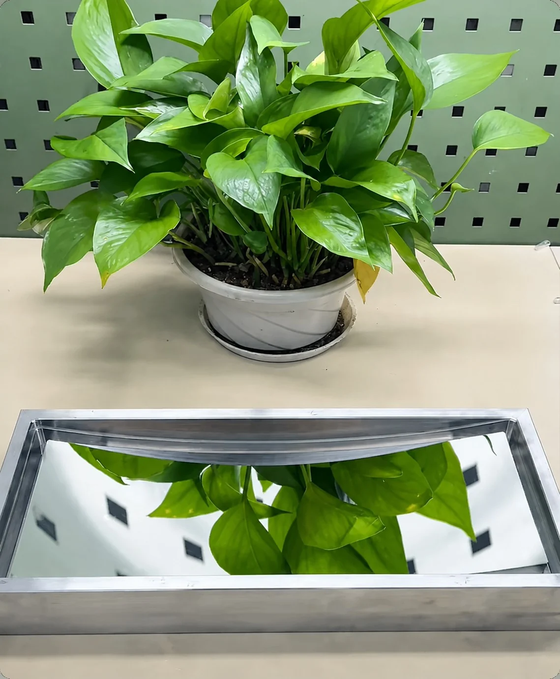
Ultra-Precision Machining Experience
More than two decades of experience in difficult ultra-precision machining and optical mold insert projects.
Experienced Technical Staff
A senior technical team supports machining judgment, process planning and problem-solving on demanding custom projects.
Complex Optical Surface Support
Large reflective surfaces, replacement inserts and difficult freeform geometry are reviewed according to the real optical risk.
The surface can look acceptable and still fail optically
HUD optical surfaces are sensitive to errors that may be difficult to see on the insert itself but become obvious once the surface is used for projection and reflection.
Roughness does not reveal every form error, local waviness or reflection discontinuity.
Periodic or directional machining traces can become visible once the surface is used as a HUD reflector.
Small local differences can accumulate across a broad reflective surface and affect image quality.
Removing more material without identifying the real cause can damage the designed freeform relationship.
Solving pits, tool marks and unstable reflection on a HUD freeform insert
A German HUD project showed why optical insert problems should not be treated as a simple “polish it again” issue.
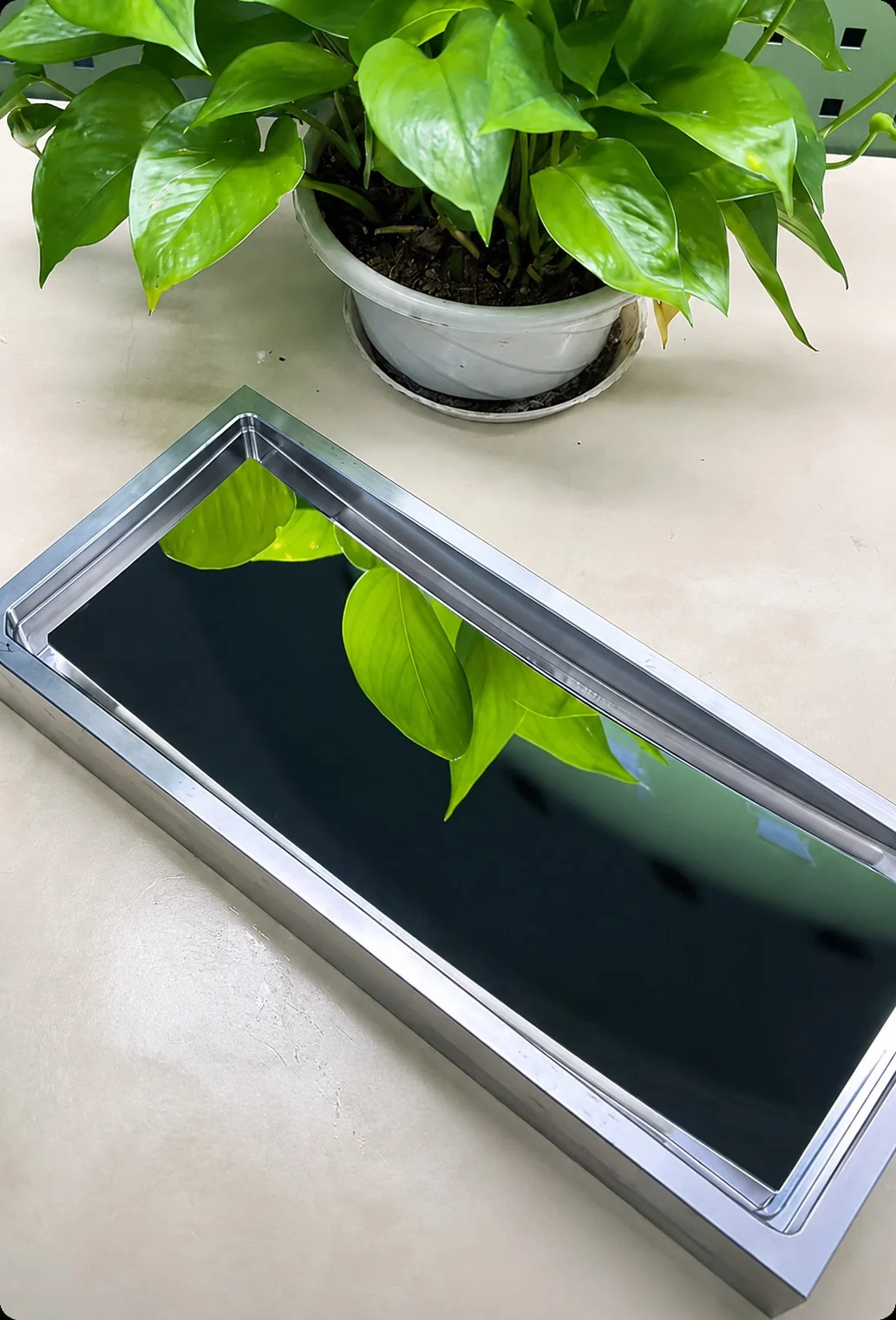
The customer’s HUD mold showed visible pits and tool marks in the reflective optical area. The surface needed to become cleaner, but the freeform geometry could not be damaged during correction.
HUD optical inserts are freeform optical surfaces, not ordinary mirror molds
The machining target is not simply brightness or a low roughness value. The insert must keep the designed optical form while maintaining a stable reflective surface over the critical HUD area.
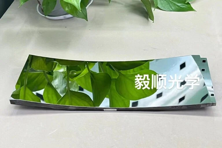
- Typical applications: AR-HUD freeform mirror inserts, HUD reflector mold inserts, large-area reflective optical inserts and replacement optical cores.
- Typical customer concerns: image distortion, unstable reflection, directional marks, local waviness, visible defects and repeatability between inserts.
- Main machining difficulty: keeping freeform geometry, surface finish and local reflection behavior under control at the same time.
- For correction projects: drawings, defect photos, measurement data and trial feedback help determine whether correction or a new insert is more appropriate.
What we pay attention to during HUD optical insert machining
The risk usually comes from the relationship between form, machining path, surface condition and reference features—not from one isolated parameter.
Freeform Surface Stability
- Whole-surface form relationship
- Local curvature transitions
- Control of over-correction
Reflection Continuity
- Continuous optical appearance
- Suppression of local reflection breaks
- Transition-zone control
Tool-Mark Direction
- Tool-path planning
- Periodic-error risk
- Directional texture suppression
Large-Area Mirror Quality
- Consistent surface behavior
- Local waviness review
- Appearance under strong light
Datum & Matching
- Reference relationship
- Assembly consistency
- Replacement insert matching
Repeatability
- Stable machining route
- Controlled process parameters
- Repeat insert consistency
Reference capability for automotive HUD optical insert projects
Final targets should always be confirmed after reviewing the actual drawing, material, optical zones and inspection method.
| Category | Reference capability / project focus |
|---|---|
| Typical tooling | AR-HUD freeform mirror mold inserts, HUD reflector inserts, large reflective optical surfaces, prototype and replacement inserts. |
| Machining methods | Five-axis mirror machining, ultra-precision machining and controlled finishing selected according to the real structure and material. |
| Surface roughness | Ra ≤ 0.005 μm has been achieved on selected automotive optical mold projects under suitable material, structure and process conditions. |
| Finished accuracy | Up to ±0.001 mm on selected automotive optical mold projects; final tolerance depends on the drawing and inspection scope. |
| Reference project size | Automotive optical mold project reference up to 500 × 460 × 240 mm. |
| Inspection focus | Critical dimensions, datum relationships, roughness, local surface condition, agreed optical-form data and appearance-critical zones. |
HUD optical insert structures we can review
AR-HUD Freeform Mirror Insert
For large reflective freeform surfaces where optical form, mirror quality and reflection continuity must be controlled together.
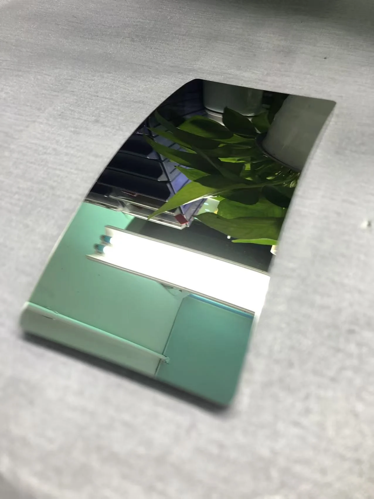
Large-Area Reflective Optical Insert
For broad optical surfaces where small local form or finish differences may become visible during projection.
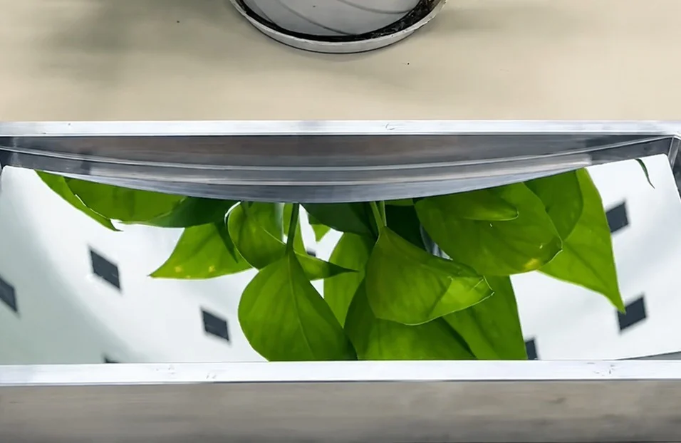
Complex Optical Core
For geometry containing local transitions, curved reflective regions or special optical zones that need separate process control.
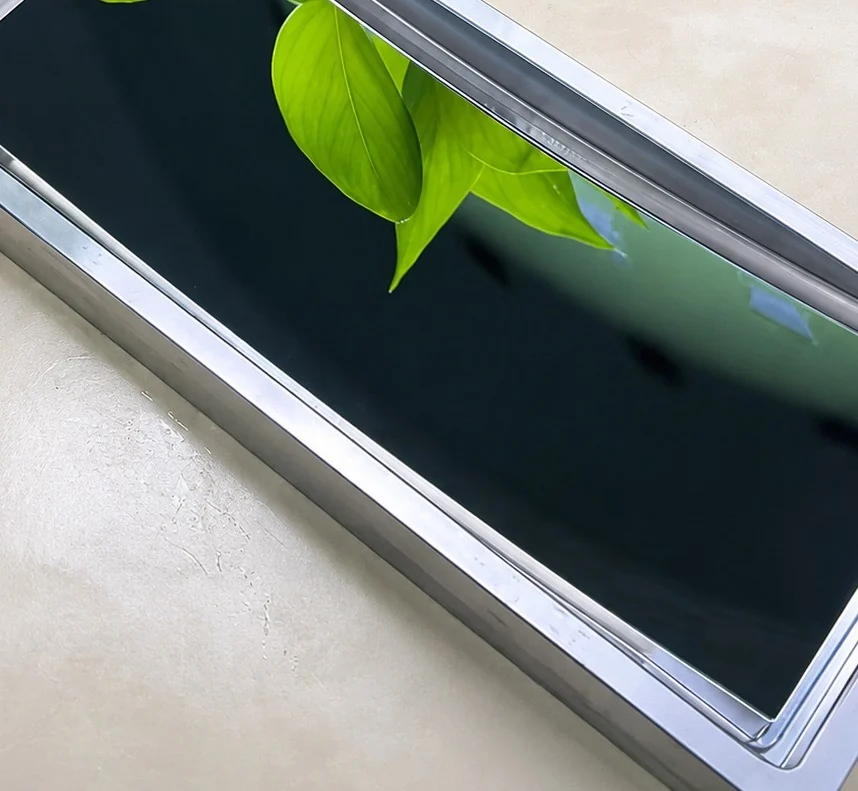
Replacement or Matching HUD Insert
For correction or replacement projects where the new insert must match an existing reference, assembly system or optical relationship.
What customers usually see, and what we investigate first
How we evaluate a HUD optical insert before delivery
A HUD insert should not be approved from one roughness number or one product photo. The acceptance logic needs to reflect the actual optical risks.
Freeform surface form
Review whole-surface geometry, local transitions and agreed optical-form zones.
Tool marks and local waviness
Check directional traces, periodic patterns and visible local surface behavior.
Reflection continuity
Evaluate the consistency of critical reflective areas according to the agreed inspection scope.
Datum and assembly relationship
Confirm the references that control positioning, matching and replacement behavior.
Critical dimensions
Verify drawing dimensions that affect fit, assembly and optical positioning.
Repeatability
For repeat or replacement projects, compare the new insert against defined common references.
The process support behind difficult freeform optical projects
HUD work usually requires machining, finishing, verification and engineering judgment to stay aligned throughout the project.
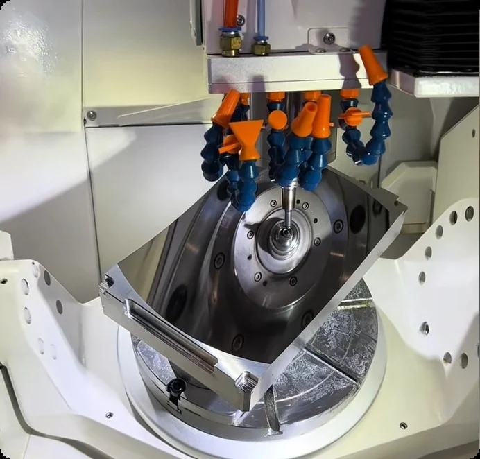
Five-Axis HUD Surface Machining
Real machining support for complex freeform surfaces where tool approach, path continuity and datum stability matter.
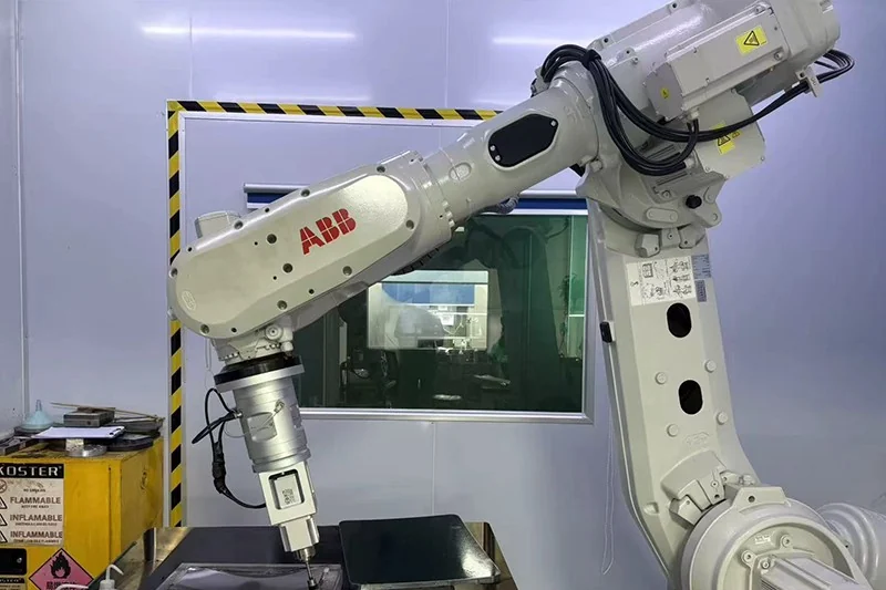
Controlled Surface Finishing
Controlled finishing helps reduce unnecessary variation on demanding mirror and freeform surfaces.
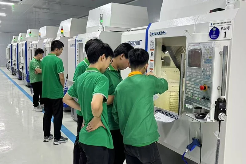
Production Workshop
A stable production environment and organized machining route support repeatable optical mold processing.
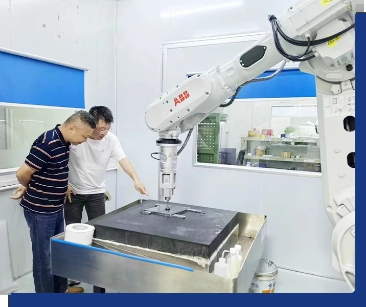
Technical Verification
Critical dimensions, surfaces and agreed optical requirements are reviewed according to the project inspection plan.
What we need before machining starts
2D drawing and 3D model
STEP, IGES, X_T and PDF data with critical dimensions and reference features.
Material and hardness
Include plating or special surface treatment if applicable.
Critical optical zones
Mark the reflection area, freeform surface and appearance-sensitive regions.
Inspection requirement
Roughness, form, critical dimensions, datums and customer-specific acceptance criteria.
Existing problem information
Photos, trial feedback, measurement data or reference samples are useful for correction projects.
Replacement or matching requirement
Provide the reference insert or dimensional relationship that must be maintained.
What machining inspection can and cannot confirm on its own
The final HUD display result also depends on the complete optical design, downstream molded component quality, assembly, projection system and vehicle integration. The insert-stage acceptance plan should therefore separate what can be verified on the mold insert from what must still be confirmed during the customer’s optical evaluation.
Documents that help us review the project more accurately
- 2D drawing and 3D model
- Material and hardness requirement
- Critical dimensions and datum references
- Optical-zone markings or freeform-surface notes
- Required surface finish or appearance standard
- Existing defect photos or sample images
- Mold-trial or optical-test feedback
- Replacement matching or assembly constraints
Frequently asked questions
Questions engineering and purchasing teams commonly ask before starting an automotive HUD optical insert project.
Can you machine AR-HUD freeform mirror mold inserts?
Yes. We review the freeform geometry, material, surface target, datum structure and inspection requirement before deciding the machining route.
Why can a HUD surface still have optical problems when Ra is already acceptable?
Because roughness is only one part of the result. Form error, local waviness, tool-path patterns and reflection continuity can also affect the projected image.
Can you help with an existing HUD insert that already has pits, tool marks or reflection problems?
Yes. Drawings, defect photos, trial feedback and measurement data help determine whether correction is practical or a replacement insert is safer.
Do all HUD optical inserts require the same machining process?
No. The process depends on geometry, material, optical zone, surface target and accessibility. The route should follow the actual project.
Can you support large reflective freeform surfaces?
Yes. Large-area optical projects can be reviewed with special attention to surface consistency, machine access, thermal stability, clamping and inspection coverage.
Can you manufacture replacement or matching HUD inserts?
Yes. These projects require careful control of the optical surface together with datums, locating features and the existing assembly relationship.
What inspection documents can be discussed for a HUD project?
Depending on the agreed plan, the project can include dimensional data, roughness records, visual inspection and other customer-required quality documents.
What should we send for a quotation and technical review?
Please provide the 2D drawing, 3D model, material, critical optical zones, surface requirements, tolerances, quantity and any current defect or trial information.
Working on a HUD optical insert that is difficult to stabilize?
Send the drawing and the real optical problem you are trying to solve. We can review the freeform surface, machining risk, finishing strategy, datum relationship and inspection requirements before production starts.