
Microstructure Optical MoldCustom Machining ThatPreserves Critical Features.
Micro-grooves, prism edges and repeated arrays must keep their designed width, depth, pitch and boundary after cutting, finishing and inspection. We review the complete feature system before selecting the machining route.
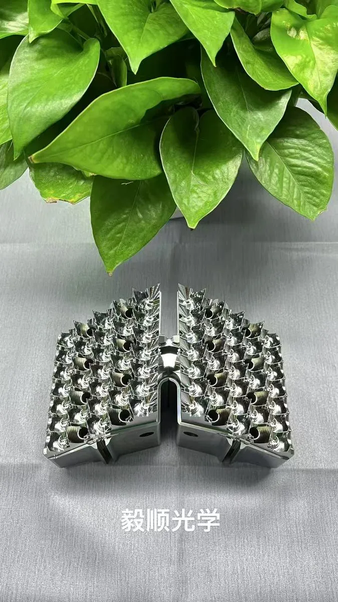
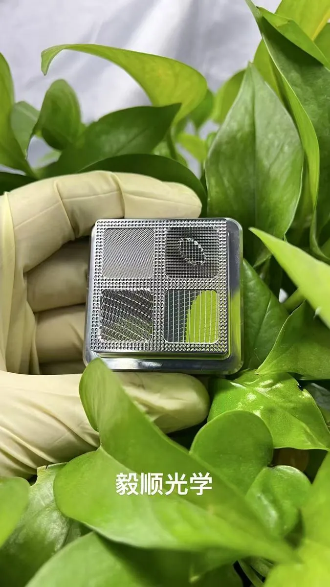
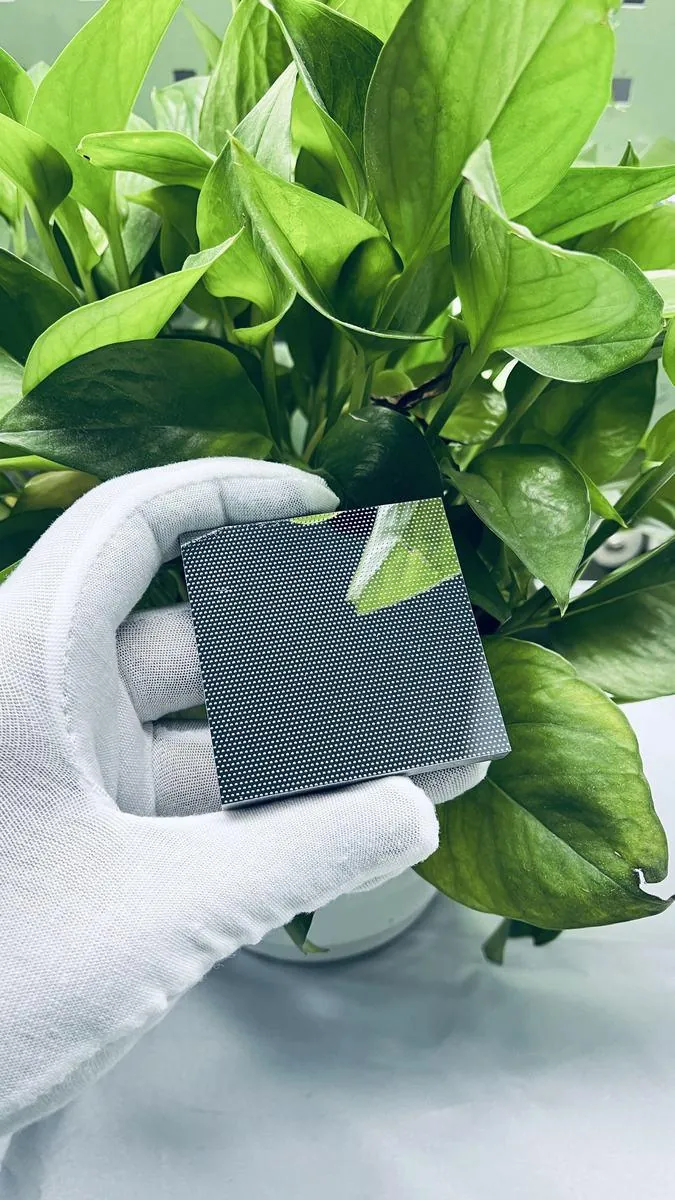
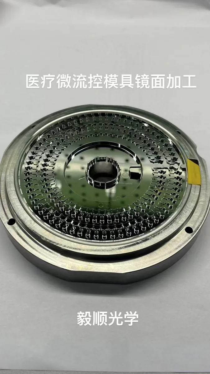
Traditional EDM was the process being replaced.
The project record documents a medical microfluidic mold program that required an alternative to the traditional electrical-discharge route for small channels and mirror-quality functional areas.
Use an R0.05 mm micro-tool ultra-precision machining route.
The route was selected to machine the small functional geometry directly while controlling channel boundaries, local surface condition and the relationship between the microstructure and the mold datum.
Judge the feature, not only the overall shine.
Critical review focused on groove width, small-radius accessibility, local dimensional accuracy, surface roughness and whether the channel edges remained usable after the complete machining route.
Different structures fail in different ways.
YISHUN custom-machines mold cores and inserts from approved drawings. The product groups below focus on optical microstructures and confirmed visible geometry, not fixed catalog parts or assumed end-use claims.
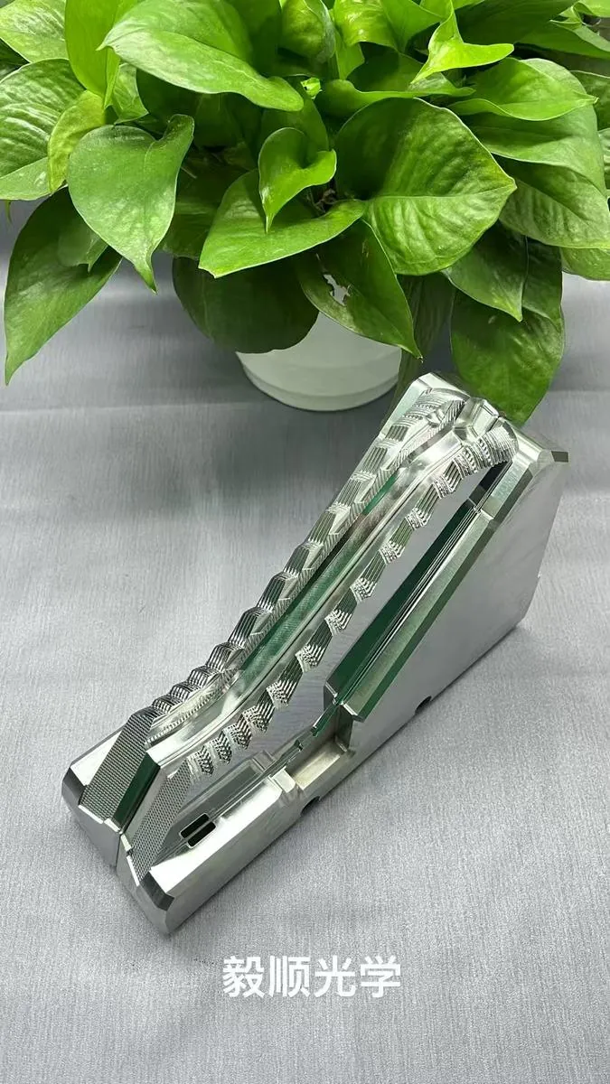
Micro-groove and linear-channel optical inserts
For light-guiding grooves, linear optical textures and other directional structures where width, continuity and functional boundaries must remain stable.
Fine micro-dot and micro-aperture arrays
Dense repeated features where local size, pitch and array uniformity influence diffusion, distribution or molded optical behavior.
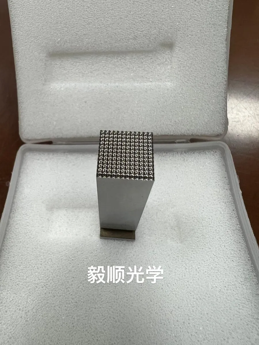
Convex and spherical micro-cavity arrays
Three-dimensional repeated features that require consistent height or depth, clean boundaries and stable surface condition across the array.
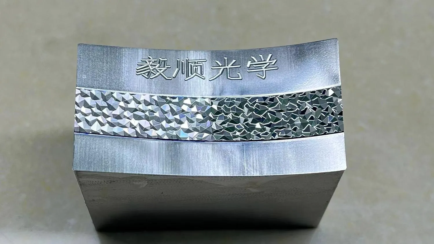
Prismatic and directional optical textures
Multi-facet, ribbed and directional structures where local edge angle and orientation must remain controlled after finishing.
Multi-zone compound optical microstructures
Several textures or pattern directions integrated into one insert, requiring protected transitions and zone-to-zone consistency.

Prototype, matched and replacement microstructure inserts
Single prototypes, repeated product families and replacement inserts where the new structure must match an existing datum and mold system.
Small geometry creates large production risk.
Microstructure optical molds are usually rejected because a functional feature changed—not because the whole insert simply lacked gloss. The main risks are geometry loss, transition damage and inconsistent replication across the array.
Edge rounding and feature collapse
Manual or uncontrolled finishing can increase local radius, lower feature height or soften a prism edge even when the surrounding surface becomes brighter.
Width, depth or pitch drift
Tool state, path compensation and material response can change a repeated groove or array gradually across the part.
Zone transition mismatch
Where two textures meet, the boundary may become blended, stepped or directionally inconsistent if the route is planned only zone by zone.
Array inconsistency between cavities
A cavity can pass by itself but still fail as part of a matched set if tool wear, compensation or inspection logic changes across production.
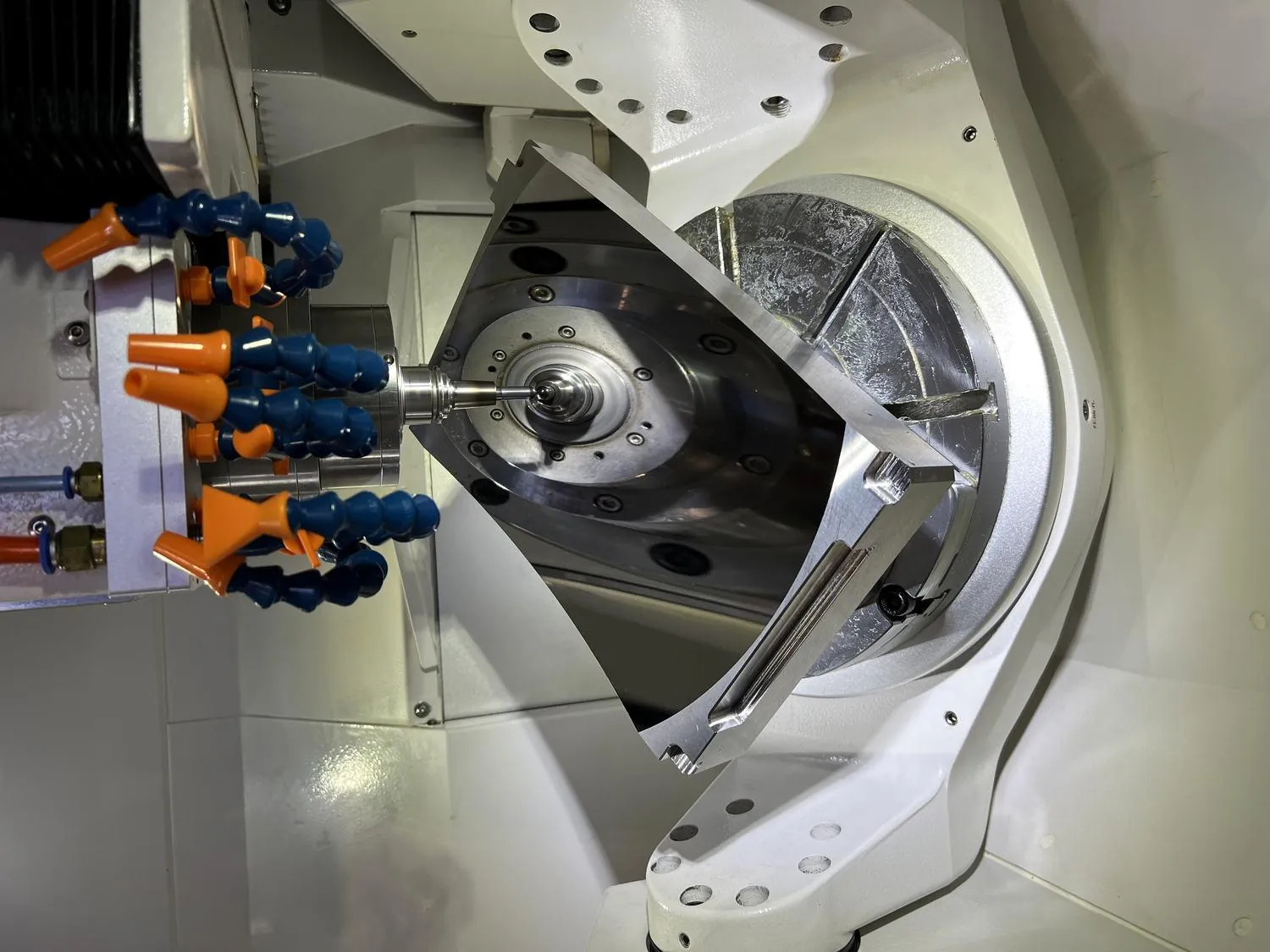
A custom process route built around the smallest functional feature.
Define the functional microstructure
Confirm the critical width, depth, pitch, radius, facet angle, protected boundary and optical zone from the approved drawing.
The smallest important feature sets the first process constraint.Build stable datums and pre-form geometry
Prepare the insert body, support surfaces and reference system before direct generation of the microstructure.
A weak datum strategy creates cumulative error across long or repeated patterns.Select the direct-generation method
Use micro-tool machining, ultra-precision turning, multi-axis machining or another suitable route according to structure direction, material and access.
Tool condition, path direction and compensation must remain controlled.Protect features during finishing
Finish only the zones that require it and avoid conventional polishing where it would round prism edges or change micro-feature dimensions.
A lower roughness value is not useful if the functional geometry is lost.Inspect at feature scale
Combine dimensional checks, magnified observation, roughness measurement and local profile comparison according to the agreed acceptance method.
Correction begins only after the source of deviation is understood.What determines whether a microstructure can be machined reliably?
There is no single universal minimum feature size. Feasibility is decided by the complete relationship between geometry, material, access, surface requirement and the inspection method.
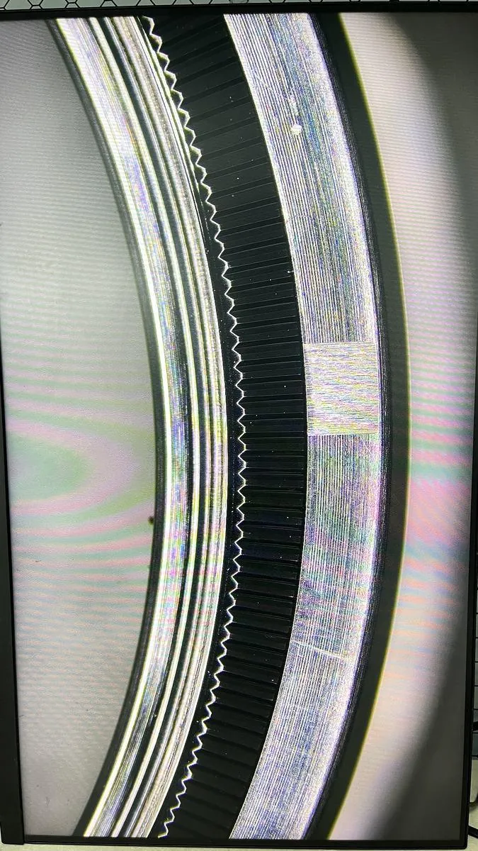
Microstructure inspection must resolve the feature itself.
A large reflective area can hide a rounded prism edge, a changed groove width or an inconsistent array. Inspection is selected according to the feature scale and the customer’s acceptance logic.
- Feature width and depth: measured against the agreed drawing and accessible inspection method.
- Pitch and array consistency: checked across selected zones or cavities.
- Edge definition: reviewed for rounding, collapse, burrs or local damage.
- Surface condition: reviewed for tool marks, pits, scratches and haze where mirror quality is required.
- Boundary continuity: checked where multiple textures or functional zones meet.
Machining and inspection behind the microstructure work.
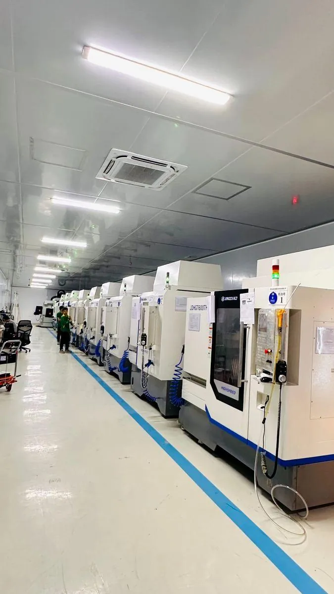
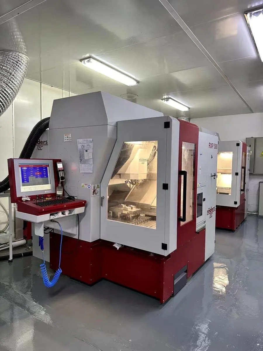
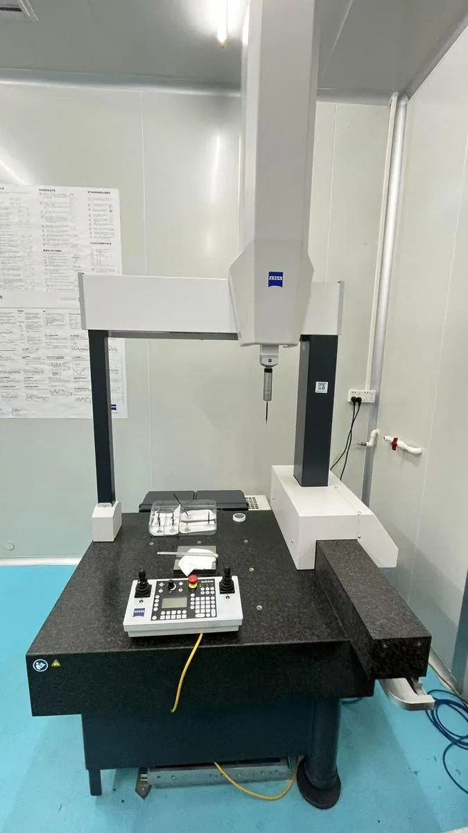
Actual YISHUN workshop, precision equipment and dimensional inspection support the custom microstructure process.
What to send for a microstructure optical mold custom machining review.
The review package should define the functional feature and its acceptance method—not only the outer mold dimensions.
Send Project Information →Questions about microstructure optical mold machining
What optical microstructures can YISHUN review?
Micro-grooves, linear textures, micro-dot or aperture arrays, spherical micro-cavity arrays, prismatic facets, directional patterns, compound zones and replacement inserts can be reviewed from the actual drawing.
Why is a medical microfluidic case included on this page?
It is a documented cross-industry process example showing the same small-feature control used in optical microstructures: narrow channels, R0.05 mm tool access, clean boundaries, dimensional accuracy and controlled surface finish.
Is R0.05 mm available for every project?
No. It is a documented case reference. Actual feasibility depends on material, depth, aspect ratio, adjacent geometry, tool access and inspection capability.
Can every microstructure be polished?
No. Fine grooves, prism edges and direct-generated arrays may lose their geometry during conventional polishing. The finishing boundary must be defined before machining.
How do you control consistency across an array?
Tool condition, path direction, compensation, datum strategy and inspection sampling are planned together. The required array and cavity comparison must be defined in advance.
What files are needed for quotation?
Provide 2D and 3D data, feature dimensions, material and hardness, functional zones, surface requirements, quantity, datum system and the intended inspection method.
Need a custom microstructure mold insert that keeps its edges, pitch and optical function?
Send the drawing, smallest critical feature, material, protected zones and inspection requirements. We will review the machining route before quotation.