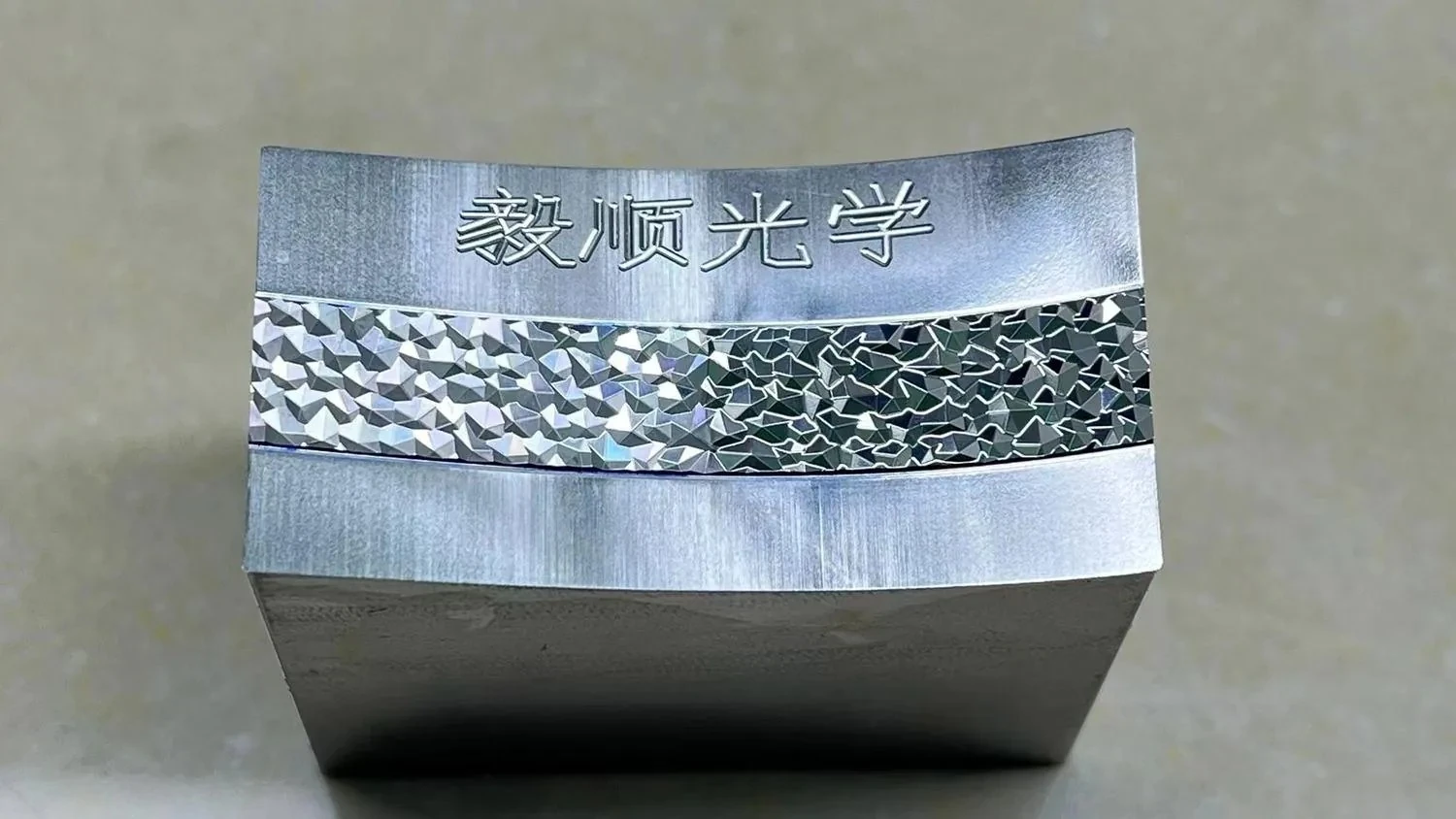
Automotive Lighting Pattern & Microstructure Mold Inserts
When a lighting pattern is built from hundreds or thousands of small facets, grooves or repeated features, a tiny change in edge shape, pitch or local direction can change the final light signature.
Yishun supports custom mold inserts for automotive lighting textures and structural optics, with machining decisions built around the smallest functional feature—not around a generic mirror-finish target.
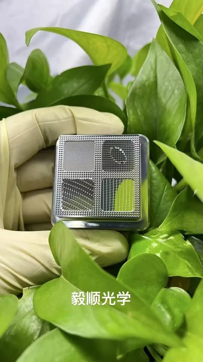
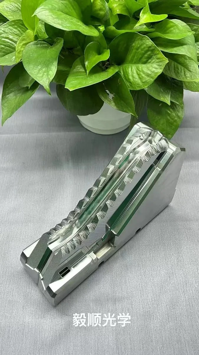
The mold pattern is part of the optical function
For automotive lamps, decorative lighting and structural optics, the machined pattern is not simply a texture. Its local geometry determines how light is redirected, broken up or distributed after molding.
Small geometry creates visible defects
Edge rounding
Finishing can soften a prism or diamond edge and change the intended reflection behavior.
Pitch or depth drift
Tool wear or compensation error can make repeated structures gradually change across the insert.
Transition mismatch
Two optical zones can each look acceptable but still create an obvious line where their pattern directions meet.
Inconsistent repeat sets
A replacement or matched insert can be dimensionally close yet reproduce a different visible pattern.
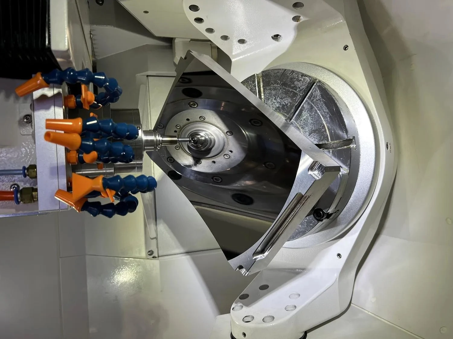
Pattern machining for automotive lamp tooling
Yishun’s documented automotive optical mold work includes vehicle-lighting pattern and lens mirror-machining projects. For this type of insert, the machining review starts from the functional pattern rather than treating the complete surface as one general mirror zone.
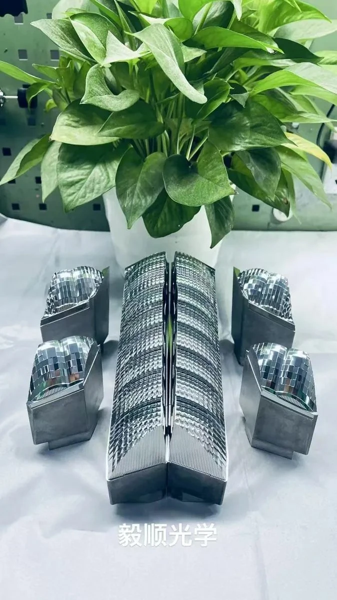
Separate diamond texture, fine micro-pattern, grooves and transition areas by optical function.
Tool radius, local accessibility and finishing allowance are defined around the feature that is easiest to damage.
Polishing or surface refinement cannot be allowed to erase the geometry that creates the lighting effect.
Inspection considers repeated geometry, local edges, transitions and the matching relationship across the insert.
Different lighting effects require different structural control
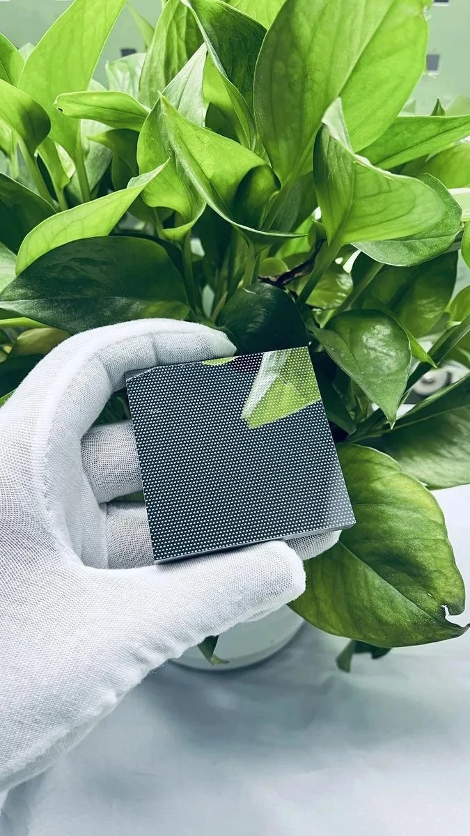
Built around the smallest functional feature
Drawing & optical-zone review
Confirm which features control the lighting effect and which boundaries cannot be rounded.
Datum and pre-form preparation
Create a stable reference system before the high-risk microstructure is machined.
Micro-feature machining
Select tool access, cutting direction and compensation based on actual local geometry.
Controlled finishing
Finish only where needed while protecting feature height, edge shape and local pitch.
Pattern verification
Check the critical structure as a complete zone rather than only measuring one sample feature.
What we check before a lighting-pattern insert is accepted
Information that helps us judge whether the pattern can be protected
Drawing & Structure Data
- 2D drawing and 3D model
- Critical width, depth, pitch, angle and local radius
- Pattern direction and protected optical boundaries
- Material, hardness and any coating/plating requirement
Optical & Matching Context
- Which zones directly influence the required lighting effect
- Approved reference insert or molded sample if available
- Known defects such as uneven brightness or pattern mismatch
- Replacement, matched-set or repeat-production requirements
Frequently asked questions
Questions commonly raised before an automotive lighting-pattern or microstructure mold insert project.
Can you machine diamond-pattern or multi-facet automotive lighting inserts?
Yes. Feasibility depends on facet angle, minimum feature size, local radius, tool access, material and the required inspection method.
Can the same process be used for all microstructure zones?
No. Different pattern types may require different tool directions, allowances and finishing boundaries, especially when several structures are integrated into one insert.
How do you avoid rounding small prism or pattern edges?
The critical boundary must be identified before finishing. Tool path, local allowance and polishing contact are then controlled to protect that geometry.
Can you support repeated arrays and large patterned areas?
Yes. These projects need consistency control across the whole functional area, with special attention to tool wear, compensation and repeated-feature inspection.
Can you reproduce an existing lighting-pattern insert?
Yes. Replacement work is reviewed together with the existing datum system, pattern geometry and approved reference information.
Does a low Ra value guarantee the lighting pattern will work correctly?
No. Roughness is only one factor. Feature geometry, edge shape, pitch, local direction and zone transitions may have a larger effect on the intended optical function.
What should we send for technical review?
Please provide the 2D/3D drawing, material, pattern dimensions, optical zones, tolerance, quantity, reference samples and any current lighting or molding problem information.
Is one small lighting feature causing a much larger production problem?
Send the drawing and identify the pattern area that matters most. We can review the micro-feature geometry, tool-access risk, finishing boundary, repeatability and inspection approach before machining starts.