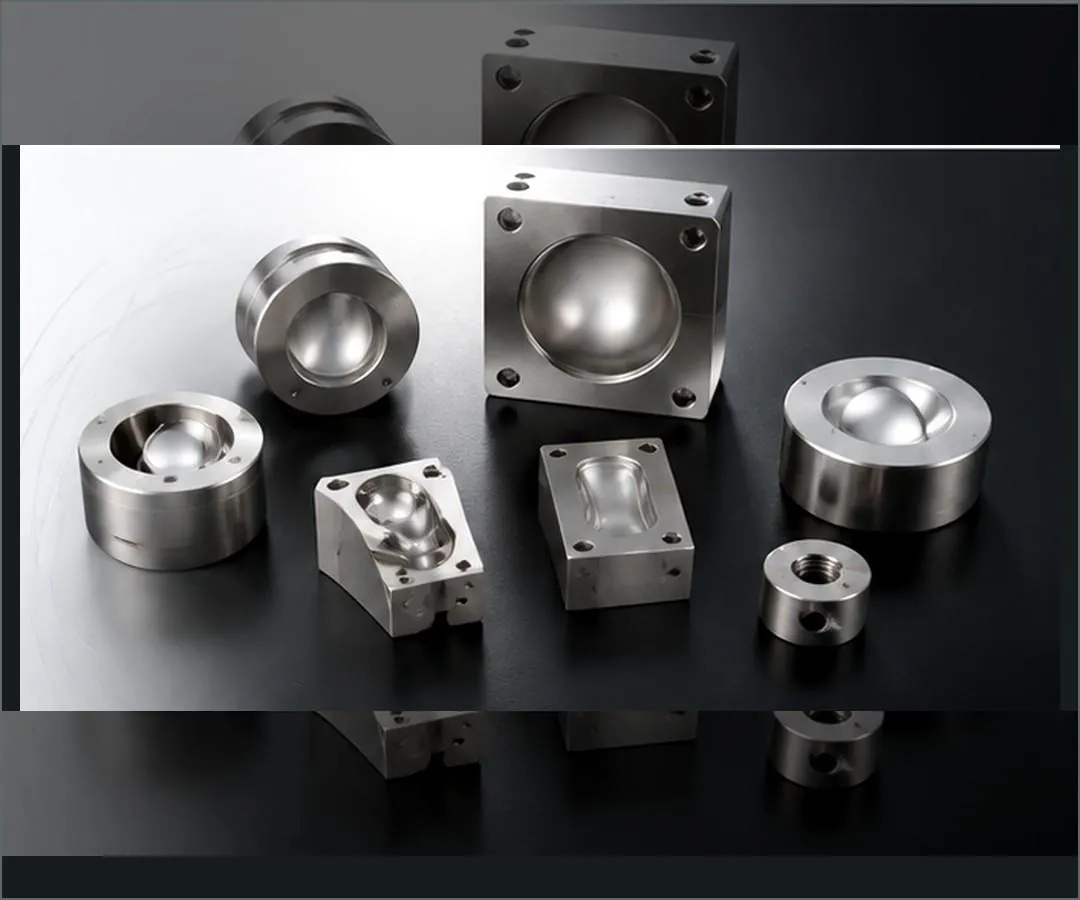
Representative aspheric optical mold insert product family
Representative product-family visual showing different aspheric mold-insert forms. It is not presented as a specific customer case.
Aspheric Mold Insert Machining

Aspheric Mold Inserts Made to Protect the Optical Profile, Not Just the Shine.

For an aspheric optical mold insert, the center, slope transition, effective aperture, edge and datum relationship must stay correct together. A bright surface that loses the designed form is not a successful insert.

≤0.005 mmSelected profile-tolerance reference for suitable projects
Ra ≤0.008 μmSelected roughness reference under suitable conditions
SPI A0Or a customer-defined mirror acceptance standard
What an aspheric-insert buyer is actually approving
Optical profileThe full concave or convex aspheric relationship, not a few isolated dimensions.
Surface conditionRoughness, scratches, pits, tool marks, haze and polishing stability across the optical zone.
Insert relationshipOptical surface position relative to the outside diameter, base and replacement references.
Aspheric optical inserts we can review and machine

The page covers more than one camera-lens mold core.

YISHUN works from customer drawings rather than a standard catalog. The following are practical product directions we can evaluate according to the surface definition, material, aperture, surrounding structure and inspection method.
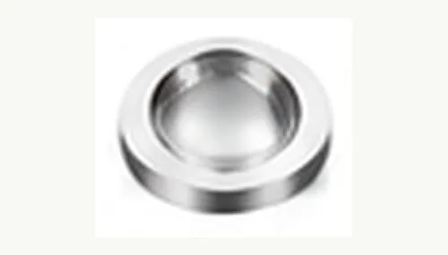
Representative imaging-lens aspheric mold insert
Imaging optics

Camera and imaging lens mold cores

Concave or convex aspheric mold cores for compact imaging lenses, machine-vision optics and related plastic lens systems.
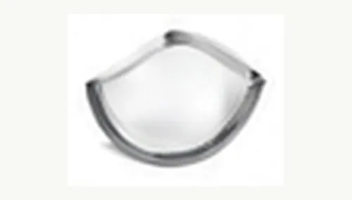
Includes the documented smartphone-camera project shown below, but is not limited to mobile-phone applications.
Representative AR VR aspheric lens insert
Near-eye optics

AR/VR aspheric lens inserts

Aspheric inserts for molded near-eye optical elements where local form, optical aperture and assembly references must remain connected.
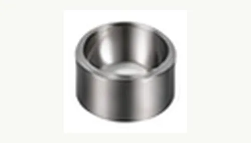
Final feasibility depends on whether the design is rotationally symmetric, freeform, dual-curve or a combined surface.
Representative optical sensor lens mold core
Optical sensing

Sensor and receiver lens mold cores

Small aspheric inserts for optical sensing, receiving, scanning or compact optical modules after drawing and material review.
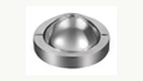
The acceptance plan may prioritize optical-axis location, edge definition and repeatable insert replacement.
Representative collimation and illumination lens insert
Illumination optics

Collimator and illumination lens inserts

Aspheric mold inserts for beam shaping, collimation and illumination lenses when the approved optical design is suitable for molded replication.
Surface type and product application must be confirmed from the optical design; a curved mirror surface alone is not enough.
Representative high-wrap optical lens insert
Eyewear optics

Safety and high-wrap lens mold inserts

Aspheric or combined-curvature lens inserts for wide-field, wraparound or protective optical-lens projects.
Mold machining supports the customer’s validation plan; certification of the finished eyewear remains a separate responsibility.
Representative concave and convex aspheric inserts
Insert configuration

Concave and convex aspheric inserts

Single inserts with internal concave or external convex aspheric surfaces, including surrounding lands, mounting diameters and datum features.
The machining route changes with surface access, material, depth and adjacent structures.
Representative multi-cavity aspheric insert set
Matched cavity sets

Multi-cavity aspheric mold-core sets

Matched cavity sets where profile, mirror condition, datum logic and cavity-to-cavity consistency must be planned together.
Cavity comparison and interchangeability requirements should be defined before production.
Representative prototype and replacement inserts
Development and maintenance

Prototype and replacement inserts

Prototype inserts for new optical programs and replacement inserts for existing molds where matching datums and existing mold condition must be reviewed.

Correction or replacement feasibility depends on remaining stock, wear, defect depth and the original inspection data.
Important: These are project categories that can be evaluated, not fixed catalog products. The images are representative product-form visuals and do not disclose a specific customer part. Final capability and the correct product name must be confirmed from the real 2D/3D data, material, aspheric definition and application requirements.
01
One Documented Production Project

Concave Aspheric Mold Core for a Smartphone Camera Plastic Lens

This is one application example within the broader aspheric-insert capability. The case is based on YISHUN’s documented mobile-camera optical mold-core project information. The customer name, surface equation and final lens design remain confidential; the material route, process logic and selected performance references shown below come from the available project record.
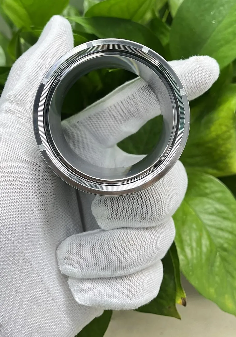
Actual circular optical mold insert produced by YISHUN
Actual YISHUN circular optical-insert photo used as a production reference. The exact customer aspheric insert is not displayed for confidentiality.

Project brief

ApplicationPlastic lens molding for rear or front smartphone camera optics.
Optical surfaceInternal concave aspheric surface that directly affects lens replication and image clarity.
Material routeS136 mold steel was documented as the base material route for this product category.
Machining routeUltra-precision single-point turning, five-axis mirror machining where required by the surrounding structure, and controlled nano-level mirror finishing.
Main riskAchieving a bright surface without changing the designed aspheric profile, rounding the optical boundary or introducing scratches, pits, orange peel, tool marks or haze.
Acceptance focusProfile, mirror appearance, roughness, edge condition and datum relationship were treated as one connected inspection problem.
Why this project matters to a buyer

The insert is not purchased as a polished metal part. It is purchased because its surface must replicate a stable optical lens. The practical value lies in reducing repeated mold correction, unstable cavity behavior and defects that can be copied into the molded lens.

Project note: selected figures are capability references recorded for suitable mobile-camera mold-core work. Final capability must always be reconfirmed from the actual drawing, material, aperture and inspection standard.
S136
Documented base materialUsed as a common optical mold-steel route for the recorded camera-lens mold-core category.
0.005
Profile reference, mmSuitable projects may be evaluated against a profile tolerance at or below this value.
0.008
Ra reference, μmAvailable when material, surface access and the complete process route are suitable.
1 / N
Single or multi-cavityThe same review logic can be extended to one insert, a matched set or replacement cavities.
One profile, changing machining conditions

The aspheric surface cannot be treated as one uniform mirror area.

Tool contact, local slope, polishing response and measurement sensitivity change from the center to the edge. The process must protect the complete relationship rather than optimize one location in isolation.

CENTER SLOPE TRANSITION EFFECTIVE APERTURE EDGE DATUM / INSERT BODY RELATIONSHIP
CenterLocal contact and compensation errors can become visible at the most optically sensitive location.
Slope transitionChanging surface angle can alter cutting and polishing behavior.
Effective apertureThe complete useful optical zone must remain continuous and stable.
Edge and datumOptical geometry must remain correctly positioned in the insert body.
How the project moves through the workshop

A decision flow built around the drawing—not a generic machine list.

The machining route changes with the surface definition, material, surrounding features and the way the customer will verify the insert.

01 · REVIEW

Surface and datum review

Confirm the aspheric definition, optical aperture, protected edge, material, outside references and report requirement.

02 · ROUTE

Choose the cutting route

Use SPDT for suitable rotational surfaces, five-axis machining for complex surrounding geometry, or a combined route where required.

03 · FINISH

Control mirror finishing

Improve the surface while protecting the center-to-edge profile, optical boundary and datum relationship.

04 · VERIFY

Close the inspection loop

Review profile, roughness, appearance and key dimensions against the same agreed acceptance logic.

Machining processes and achievable results

The process route changes with the insert—not every surface follows the same sequence.

The goal is not to list every machine in the workshop. It is to select the combination that can generate the aspheric profile, protect the surrounding structure and support the agreed inspection method.

Processes we may combine

Selected only after reviewing material, surface access, depth, aperture and adjacent features.

01
Ultra-precision single-point diamond turningFor suitable rotationally symmetric aspheric surfaces in aluminum or compatible plated non-ferrous substrates.
02
Five-axis mirror machiningFor mold steel, difficult surrounding features, restricted access or structures that cannot be completed by a turning route alone.
03
Precision grinding and pre-form controlUsed where the material, stock condition or geometry requires a stable pre-finishing route before mirror processing.
04
Controlled mirror polishing and local correctionApplied only where needed, with attention to profile retention, edge protection and avoiding local over-correction.
05
Measurement feedback and re-machining decisionsInspection data is interpreted against the same datum and optical aperture before additional material is removed.

What the finished process is intended to achieve

Actual values remain dependent on the approved drawing and acceptance plan.

PROFILEStable center-to-edge aspheric formReduce local form loss at the center, slope transition, effective aperture and optical boundary.
SURFACEMirror quality without hiding geometry lossSupport SPI A0 or customer-defined mirror standards while controlling scratches, pits, tool marks, orange peel and haze.
REFERENCEProtected edge, land and datum relationshipKeep the optical surface correctly positioned relative to the bottom face, outside diameter and assembly references.
CONSISTENCYMatched cavity and replacement behaviorPlan tool condition, finishing order and inspection logic for multi-cavity sets or replacement inserts.
SELECTED DATA≤0.005 mm / Ra ≤0.008 μmSelected project references under suitable conditions, not automatic limits for every material or geometry.
Actual YISHUN product and process evidence

Real photos are used here; customer-specific aspheric geometry remains confidential.

The circular mirror insert photos show actual YISHUN optical-insert work. They are presented as production evidence rather than claiming to disclose the exact confidential camera-lens mold core.
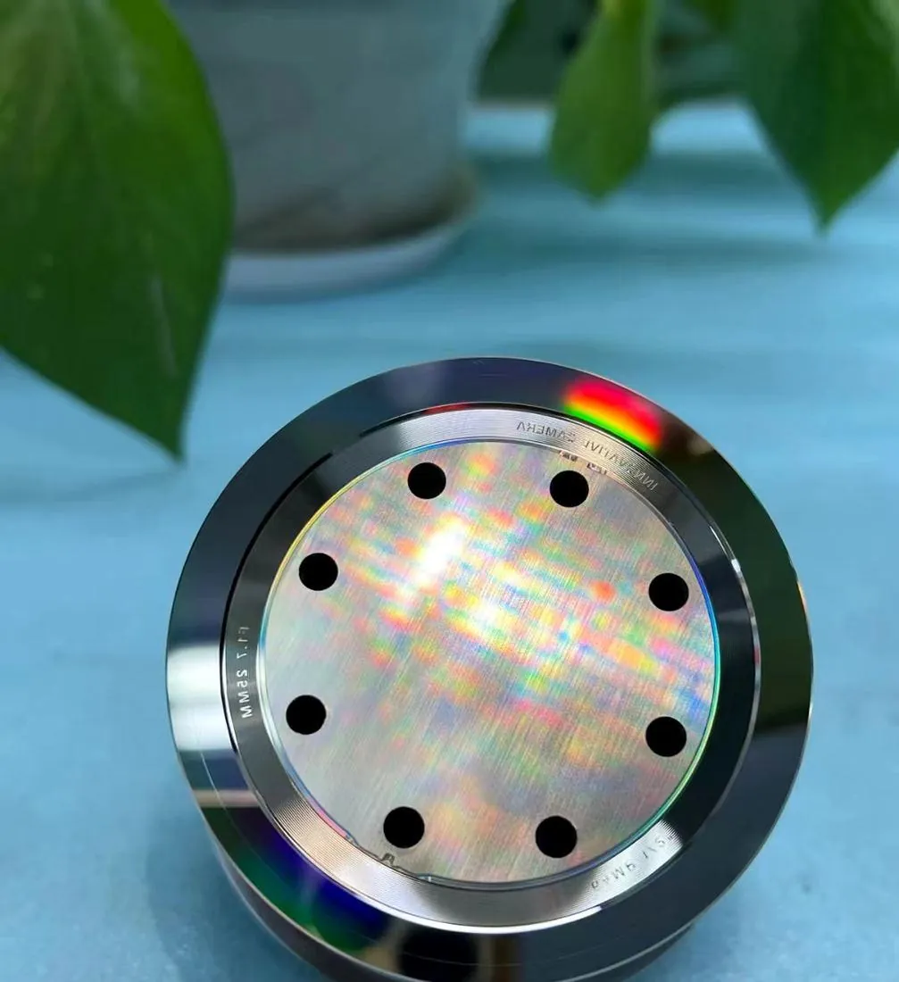
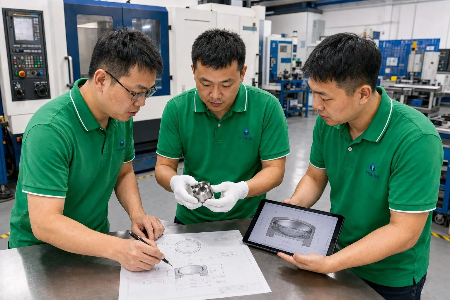
YISHUN engineers reviewing an aspheric optical mold insert and technical drawing
Before material is removed

The useful questions are asked during drawing review.

Whether the insert is used for imaging, sensing, illumination, eyewear or another molded optical system, the project becomes easier to control when the optical surface and the insert body are reviewed as one part. The review should resolve the following before the finishing route is fixed.

  • What is the effective optical aperture? The area outside it may follow a different acceptance rule.
  • Which surfaces define assembly? Bottom face, outer diameter and locating features affect replacement stability.
  • Where is polishing prohibited or limited? Edges and transitions can lose geometry quickly.
  • How will the aspheric profile be measured? The agreed method must match the drawing and datum system.
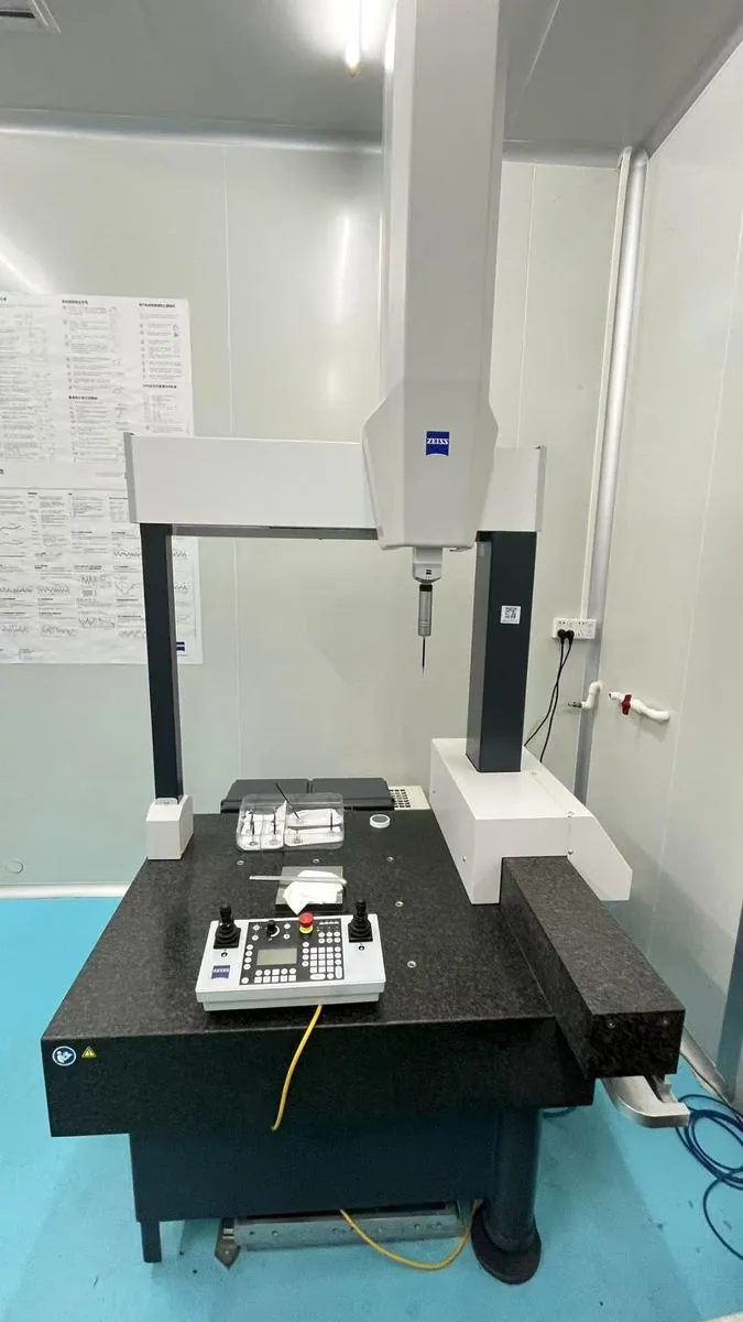
Zeiss coordinate measuring machine at YISHUN
Inspection ledger

One report cannot answer every optical-mold question.

The inspection package is selected according to the actual project. The available internal record includes CMM, roughness inspection, microscope inspection, appearance inspection and form inspection when necessary.

DimensionsKey insert-body dimensions, mounting relationships and replacement features.
Profile / formAspheric surface comparison where the agreed measurement setup supports it.
RoughnessMeasured on agreed zones and interpreted with the visual and functional requirement.
AppearanceScratches, pits, tool marks, orange peel, haze and local surface changes.
Multi-cavityComparison data where cavity-to-cavity consistency is part of the customer’s acceptance plan.
Real YISHUN production environment

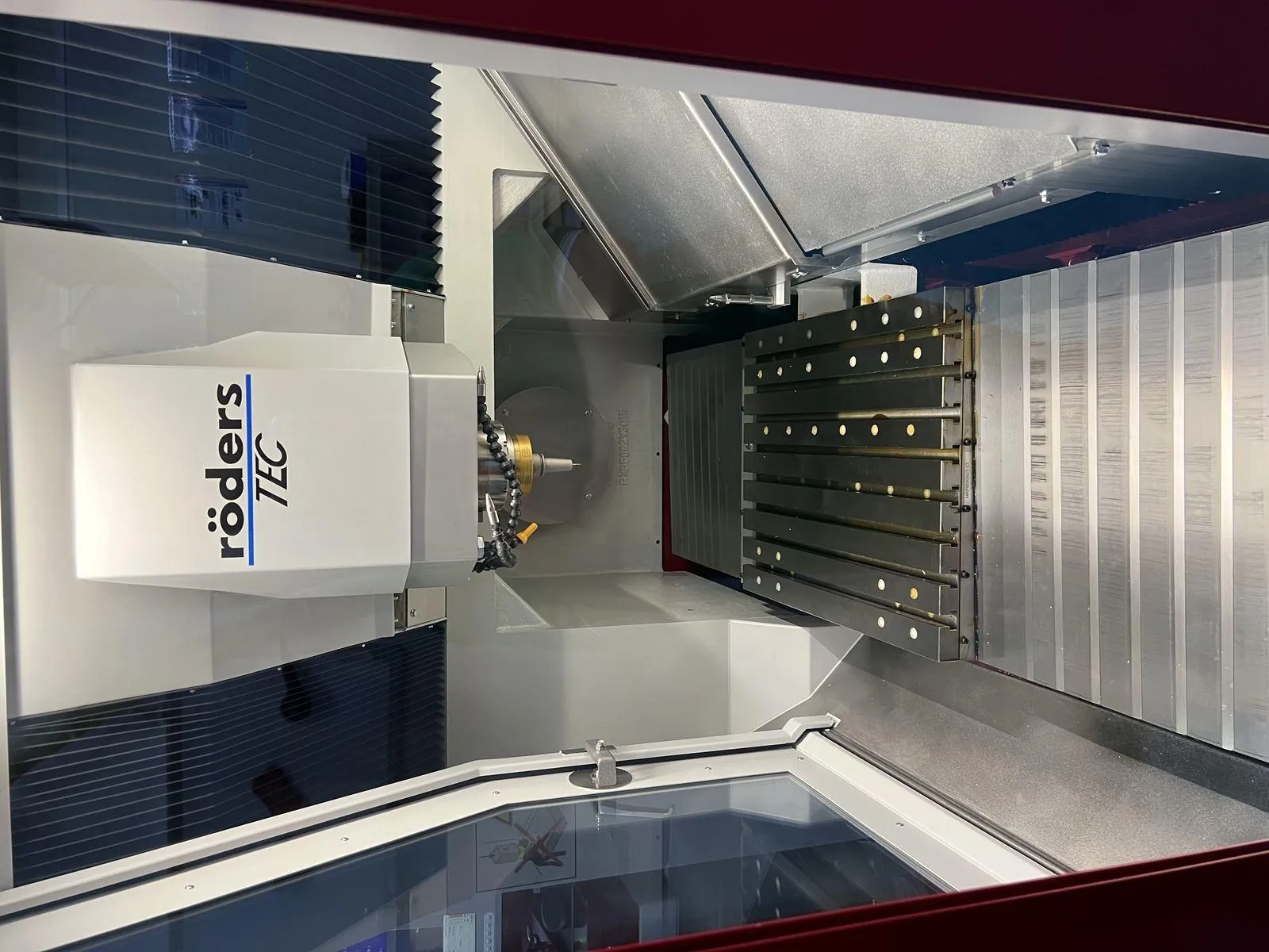
Inside YISHUN’s Precision Machining Workshop
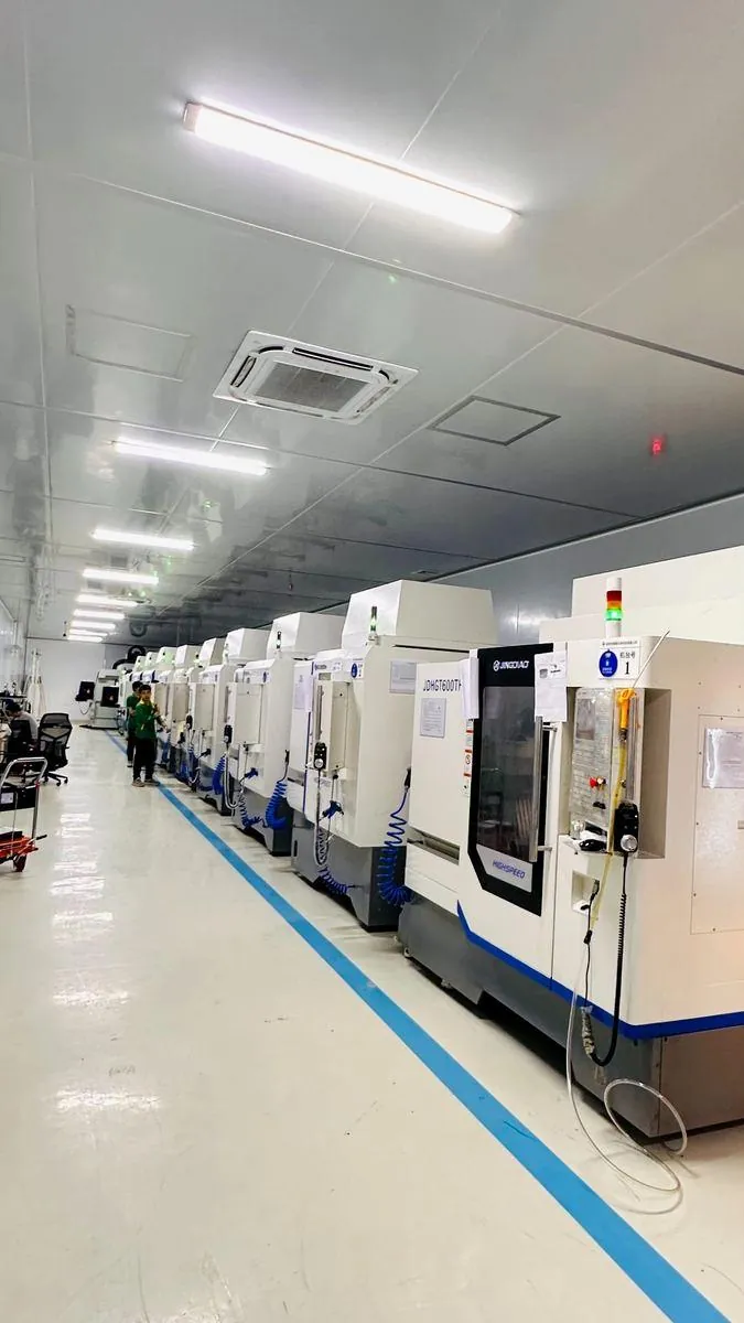
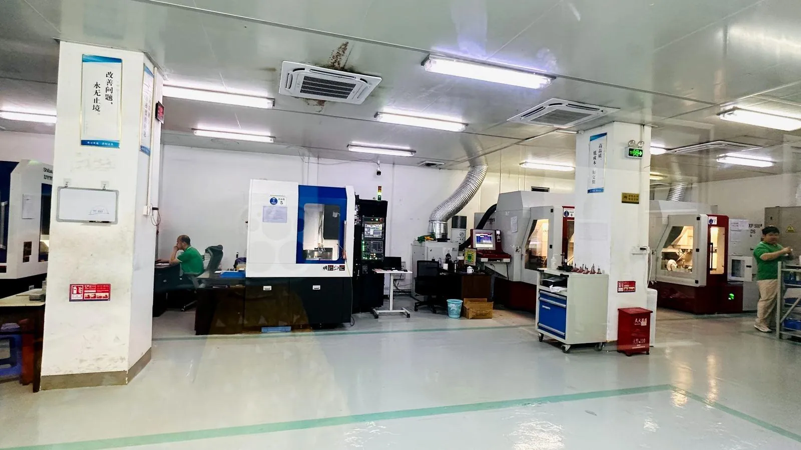
YISHUN precision machining workshop with a row of machines
Real YISHUN machining line with multiple precision machines in operation.
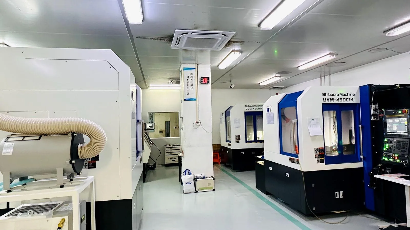
YISHUN ultra-precision machining equipment area
Shibaura ultra-precision machining area inside the actual workshop.
Wide view of the YISHUN machining workshop
Real production floor showing equipment, operators and supporting work areas.
Project capability reference

Numbers shown with their limits and conditions.

These are not universal promises. They are references recorded for suitable projects and must be reconfirmed from the actual drawing.

Request Drawing Review →
Product categoryCustom concave and convex aspheric mold cores, prototype inserts, replacement inserts and matched cavity sets.
Typical useImaging lenses, AR/VR optics, optical sensing, illumination/collimation lenses, safety eyewear and other molded optical systems after drawing review.
Material routeS136 mold steel and other compatible materials after machining and polishing review.
Surface standardSPI A0 or a customer-defined mirror standard when the material and geometry are suitable.
Profile reference≤0.005 mm on selected suitable projects.
Roughness referenceRa ≤0.008 μm under suitable material, access and process conditions.
Micro-feature referenceR0.05 mm micro-tool mirror-machining experience on selected projects.
Spindle referenceSelected equipment up to 60,000 rpm.
Inspection optionsCMM, roughness, microscope, appearance and form inspection where required.
FAQ

Questions about aspheric mold insert machining

Is every circular optical insert an aspheric mold insert?

No. The actual surface definition must come from the approved drawing or aspheric equation. A circular appearance alone does not prove the surface type.

Can every project reach ≤0.005 mm profile tolerance?

No. Surface definition, aperture, material, surrounding structure, setup and inspection method all affect the result.

Can every project reach Ra ≤0.008 μm?

No. This is a selected-project reference and depends on material, local slope, access and the complete finishing route.

Do you support steel and non-ferrous routes?

Yes, after review. The selected route may use ultra-precision turning, five-axis mirror machining or controlled finishing depending on the material and geometry.

Can replacement aspheric inserts be matched to an existing mold?

Potentially. The existing datum system, mating dimensions, remaining mold condition and customer acceptance method must be reviewed.

What should be included in a quotation package?

2D/3D files, surface definition, material, hardness, aperture, roughness, datum, cavity quantity and inspection requirements.

Start with the actual surface data

Need an aspheric optical mold insert that stays accurate after mirror finishing?

Send the approved drawing, aspheric definition, material, aperture and inspection requirement. We will review the center-to-edge risk, datum relationship and practical machining route before quotation.

Start Your Project With A Free Quote

Our professionals are available to talk you through each of our offerings. We’ll be sure to answer you within 24 hours. Fill out the information below with as much detail as possible, and we’ll get back to you promptly.