
Custom optical mold core & insert machining
Custom Optical Mold Core & Insert Machining for Critical Surfaces
YISHUN provides build-to-print machining and selected corrective support for optical mold cores and inserts with mirror, freeform and micro-structured surfaces. We connect drawing review, ultra-precision machining, five-axis mirror machining, controlled finishing and agreed inspection in one project route.
For suitable materials and geometry, our Moore 250UPL v2 platform is specified for form accuracy ≤0.1 μm and surface roughness ≤2.0 nm; Toshiba UVM equipment provides 0.001 mm positioning accuracy and 0.0005 mm repeat positioning. Final part capability is confirmed only after drawing and inspection review.
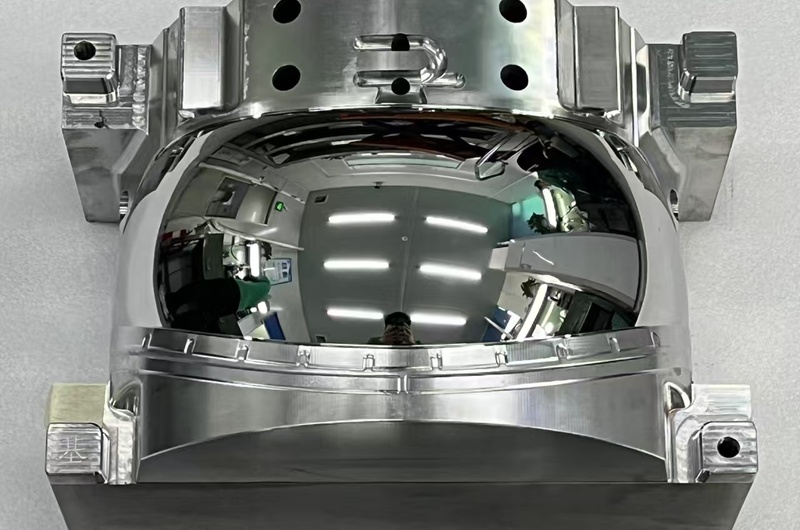
Material, geometry, critical zones, tool access and acceptance method are reviewed before the route is confirmed.
Equipment references describe machine capability under suitable conditions—not a blanket promise for every insert. Material, size, geometry, tool access and the agreed measurement method determine the final achievable result.
A real machining problem
When “mirror bright” is not the same as optically correct
A customer came to us with a HUD reflector insert showing pitting and visible tool marks. Repeating the same finishing step would only make the surface brighter while risking the intended form.
We did not ask, “How do we polish it again?” We asked, “Which process created the defect, and which geometry must not move?”
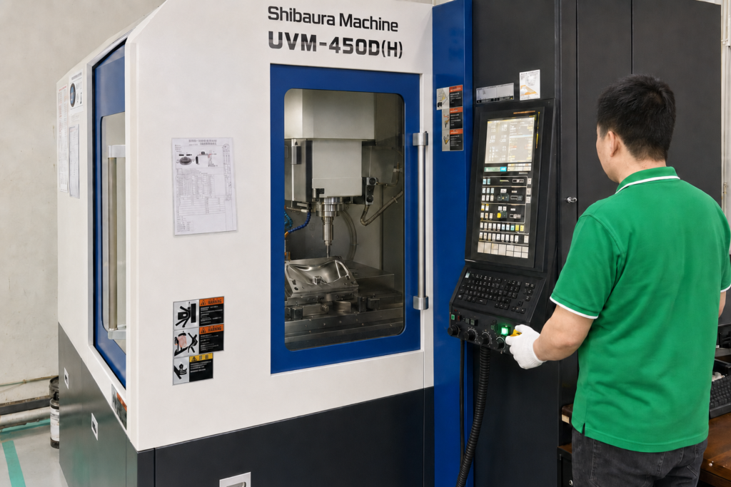
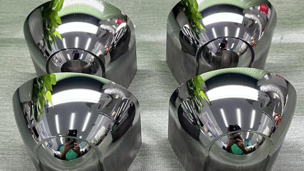
Five-axis mirror machining used as a corrective route
After reviewing the affected surface, tool access and remaining correction allowance, the team selected a controlled five-axis mirror-machining route instead of blind re-polishing.
Baseline evidence: The defect locations were photographed and mapped before correction, separating the affected zone from surfaces that were already acceptable.
Process-control basis: Tool paths were released only after the protected geometry and local allowance were defined. The available equipment references include 0.001 mm positioning and 0.0005 mm repeat positioning.
Acceptance evidence: Form and dimensions are checked against the agreed drawing by CMM or profile comparison where required. Roughness records, microscope review and matched reflected-line images verify the surface separately from visual gloss.
The equipment values describe available process control, not a blanket part tolerance or a confidential customer result. Final acceptance remains tied to the customer-approved drawing and agreed inspection method.
Featured applications
Different optical inserts fail in different ways
Choose an application to see representative insert types. Each card links to the related product page.
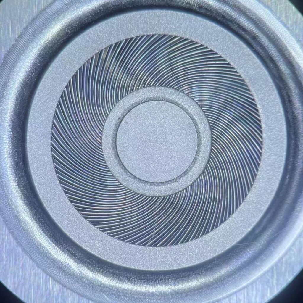
Phone Camera Optical Mold Cores
Small optical zones, concentric geometry, fine transitions and repeatable multi-insert results.
View application →
Automotive Optical Inserts
Large reflective surfaces, freeform form control, smooth transitions and visible reflection continuity.
View application →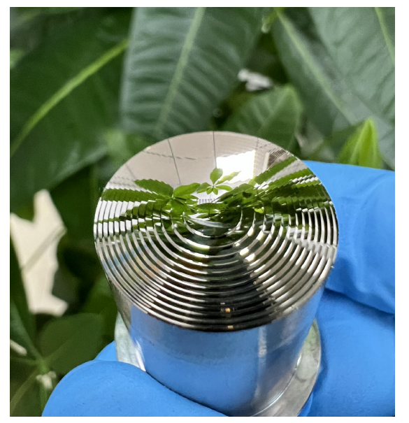
Fresnel Lens Mold Inserts
Facet angle, pitch, groove depth, center geometry and edge fidelity without damaging the active structure.
View application →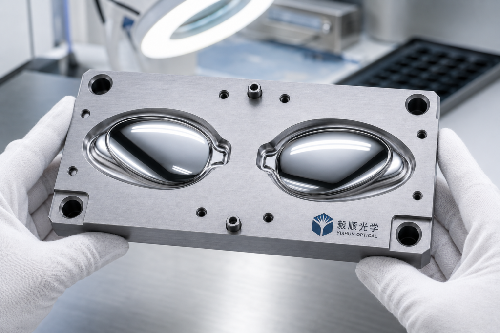
Swimming Goggles Lens Inserts
Paired left-and-right surfaces, optical-center position, visual balance and edge consistency.
View application →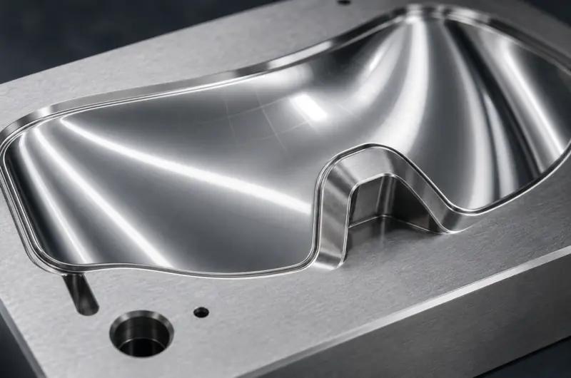
Safety Glasses Lens Inserts
Wide viewing zones, freeform cavities, distortion risk and clean transitions into surrounding geometry.
View application →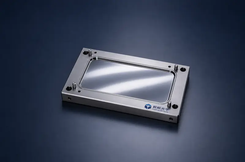
Phone Housing Mirror Inserts
Appearance-critical A-surfaces, controlled reflected lines, sharp details and uniform broad-area finish.
View application →Machining route selection
The route follows the material, geometry and risk
A plated diamond-turnable insert and a hardened steel freeform insert should not be forced through the same process. The final route is confirmed after drawing review.
 Real YISHUN equipment · Nanotech 250 UPL v3
Single-Point Diamond Turning
For suitable non-ferrous or plated substrates where optical form and finish can be generated directly.
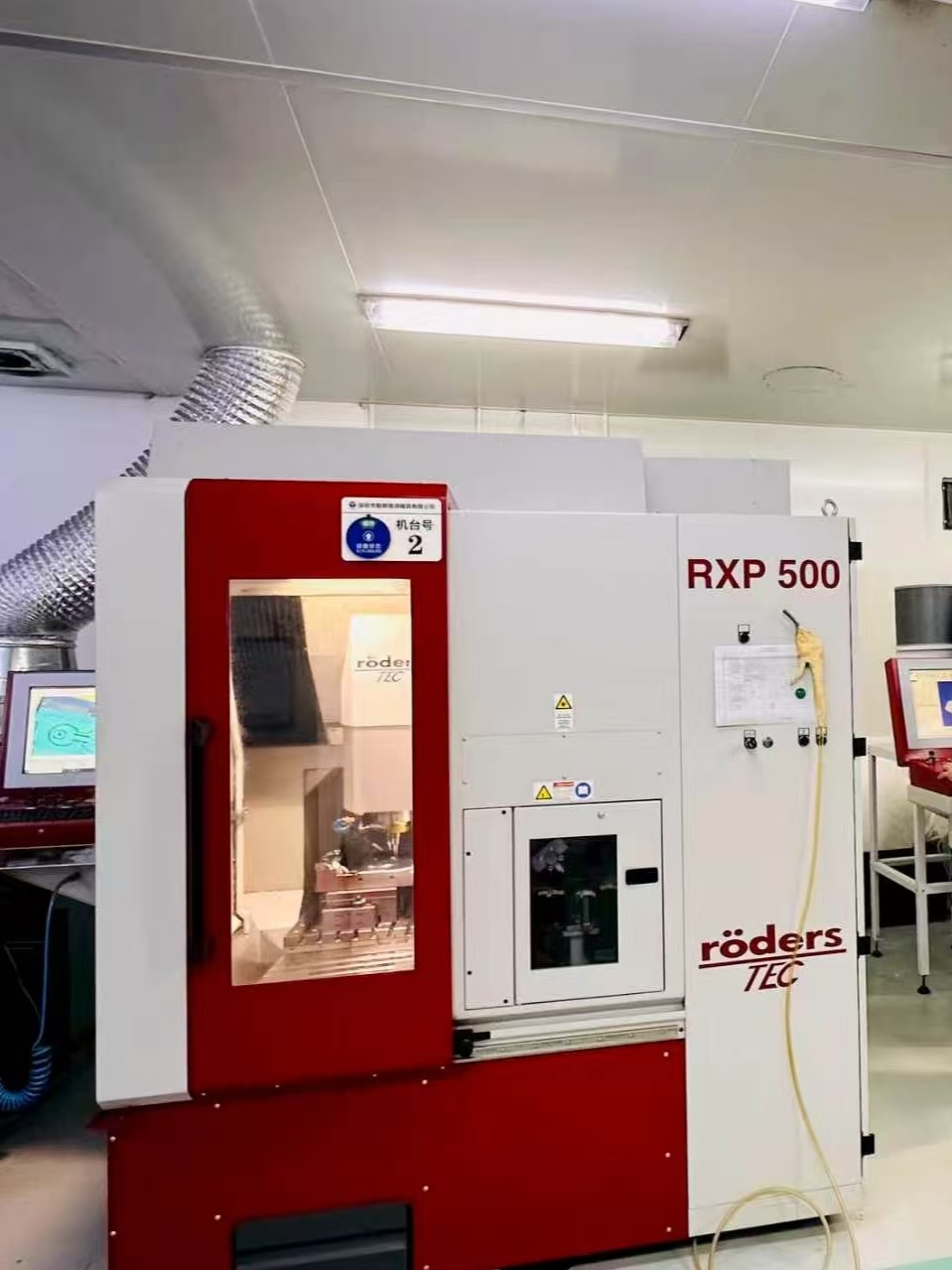 Real YISHUN workshop · Röders RXP 500
Five-Axis Mirror Machining
For complex, off-axis or freeform steel inserts where tool access and transition control are critical.
Real YISHUN workshop · Toshiba UVM-450D(H)
Ultra-Precision Grinding
For hard materials, controlled stock removal and stable preparation before final surface finishing.
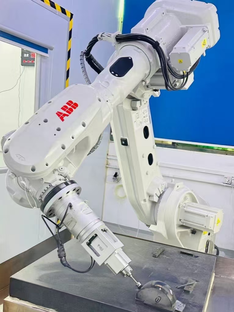 Real YISHUN equipment · ABB six-axis system
Combined Machining & Finishing
For parts that need machining, grinding and controlled local finishing without treating every zone alike.
Critical optical / appearance zone
Edge & transition protection
Reference / non-critical surface
Zone-based control
Control the area that actually causes the problem
Treating an entire insert as one surface can create new defects. We separate the part by function before machining and finishing.
Critical Optical Surfaces
Protect form, local texture, reflection continuity and the geometry that controls optical performance.
Transitions, Edges & Fine Features
Limit rounding, edge roll-off, step loss and unintended blending between neighboring zones.
Protected or Non-Critical Areas
Define surfaces that need dimensional stability, masking, reference retention or no further finishing.
The people behind the surface
The Team Behind Every Critical Machining Decision
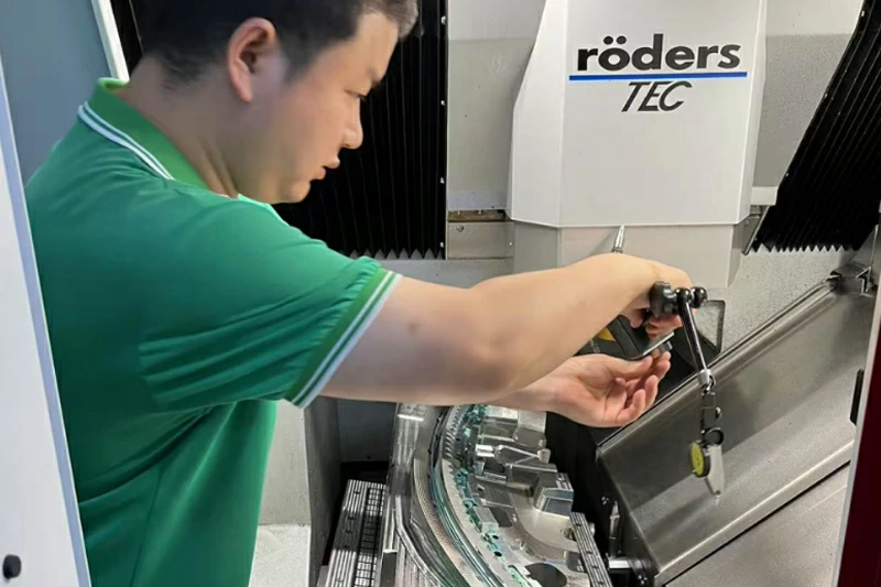
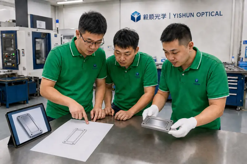
Experience is not a slogan on this page. It appears in the questions asked before quotation, the machining route selected for the real risk, and the way engineering, operators and inspection staff respond when the surface does not behave as expected.
Technical Review
2D and 3D data, material, critical zones, tolerances and acceptance logic are reviewed before the route is finalized.
Risk-Based Decisions
Tool access, clamping, material behavior, remaining allowance and protected areas guide the process—not habit.
Experienced Judgment
Tool marks, pitting, waviness or reflected-line defects trigger cause review instead of automatic repeat polishing.
Machining + Inspection
Ra is considered together with form, edges, transitions, local defects and the customer’s functional validation.
From project inquiry to delivery
A clear route from technical question to accepted insert
The workflow is kept simple for the customer, while technical decisions are made before they become machining problems.
Technical Evaluation
Review application, drawing, material, critical zones, form, surface and inspection expectations.
Commercial Confirmation
Confirm scope, quantity, responsibilities, proposed route and the information still needed.
Project Execution
Programming, setup, machining, controlled finishing and in-process checks follow the approved plan.
Delivery & Support
Final inspection, agreed records, protected packing and feedback support for validation or follow-up work.
Project review
Information Needed for Project Review
A roughness value or product image alone is usually not enough to evaluate an optical insert project. Please provide the available information below.
Drawing & 3D Data
Available 2D drawings and 3D models.
Application & Insert Type
Final application and the type of core or insert required.
Material & Condition
Material, hardness, coating and current part condition.
Critical & Protected Areas
Optical zones, edges, transitions or surfaces that must not be altered.
Form & Surface Requirements
Dimensional tolerance, form accuracy and surface requirements.
Inspection & Acceptance Method
Required inspection method and acceptance criteria.
Quantity & Target Schedule
Required quantity and expected delivery schedule.
For Re-Machining or Local Correction
Please also provide the affected location, visible or functional problem, previous machining or polishing history, and any known correction allowance.
Frequently asked questions
Questions customers ask before drawing review
Are these standard optical mold cores and inserts?
No. Each project is reviewed from the customer’s drawing, material, critical surfaces and acceptance requirements. The machining route is not selected from a fixed catalog.
Does this service include complete mold manufacturing or injection molding?
The core scope of this page is custom machining, re-machining and local correction of optical mold cores and inserts. Any additional scope must be confirmed separately during review.
Can the machining route be selected from the required Ra value?
Not reliably. Material, geometry, form, tool access, edge protection and the inspection method can be as important as the roughness value.
Can different areas of one insert use different processes?
Yes. Critical optical areas, transitions, protected edges and non-critical surfaces may need different machining or finishing controls.
Can you re-machine or locally correct an existing insert?
Often, yes. Feasibility depends on the remaining allowance, recoverable datums, current surface condition and whether the critical geometry can still be measured and protected.
What information should we send for an engineering review?
Send the available 2D and 3D data, application, insert type, material, critical zones, form and surface requirements, acceptance method, quantity and target schedule.
Can you confirm machining capability before reviewing the drawing?
We can discuss the general process, but final capability must be confirmed after the drawing, material, geometry, required result and inspection method are reviewed together.
How are quotation and delivery schedule determined?
They are determined after the technical scope, material, process route, inspection needs, quantity and current project condition are understood.
How will the completed insert be accepted?
Acceptance follows the approved drawing and the inspection method agreed for the project. Surface appearance alone is not used when form or optical function is also critical.
Start with the difficult area
Have an optical mold core or insert project to review?
Send the drawing, available specifications and the problem you are trying to solve. Our team will review the critical risks before recommending a route.