Custom Machining for Phone Camera Optical Mold Cores
For mobile phone camera lens projects, a mold core is not acceptable simply because it is dimensionally correct or visually bright. The practical concern is whether the optical surface, micro-features and cavity geometry can be replicated consistently from sample validation into production.
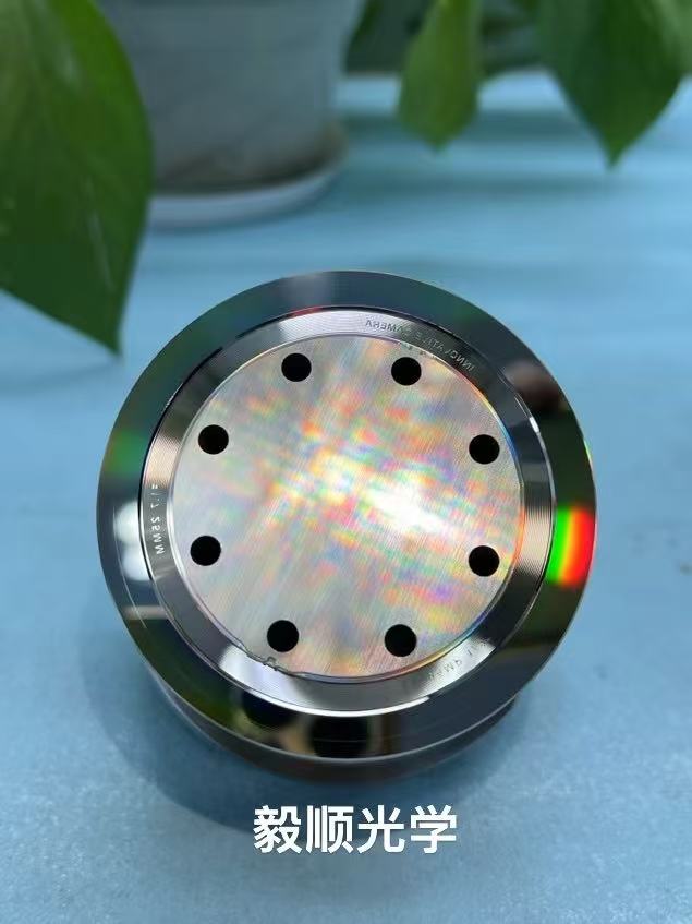
Surface form, finish, cavity consistency and replication stability are reviewed together.
More than a bright mold surface
A phone camera lens mold core should be judged by more than surface brightness. Surface form, local defects, micro-feature definition and cavity consistency all influence how reliably the optical geometry can be replicated.
Optical surface control
Local form error, tool marks, haze and roughness variation can affect how the molded optical surface is replicated.
Micro-feature definition
Small grooves, steps, texture zones and thin structures need to retain their designed geometry during machining and finishing.
Cavity-to-cavity consistency
For multi-cavity projects, each mold core needs to stay within the agreed dimensional and surface-quality window.
Stable project handoff
Drawing interpretation, inspection references and acceptance requirements need to be confirmed before machining begins.
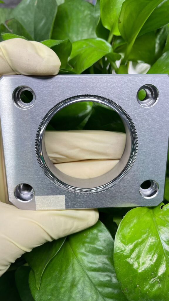
Phone camera mold cores are application-specific optical tooling
Mobile phone camera optical mold cores are used for plastic lens and related optical-part molding in rear main cameras and front cameras. The same project can combine optical surfaces, micro-structures, mirror zones and reference features, so the machining route needs to be chosen from the real drawing rather than from one fixed process.
Types of camera mold cores we can evaluate
Aspheric lens mold cores are supported as one optical-surface configuration within camera projects. Detailed aspheric machining capability is covered on the dedicated capability page.
Rear camera optical lens tooling.
Compact optical mold inserts for front camera systems.
Spherical optical surface configurations based on drawing data.
Supported as one optical-surface type; dedicated aspheric capability is covered separately.
Fine grooves, texture zones and local structured areas.
Including replacement cavities and new-project sample cores.
Precision cavities where reference and assembly relationships matter.
Mirror-finish and appearance-critical camera-related mold inserts.
Replacement machining for existing camera mold systems after drawing review.
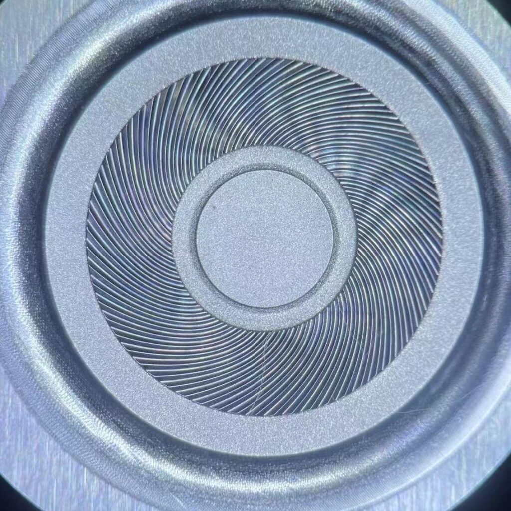
Small structures should not be “finished away”
As camera components become smaller, the difficulty often shifts from overall size to local geometry. Micro grooves, small steps, thin structures and sharp transitions can lose definition if machining or polishing removes too much material.
Reference capability — final values depend on the drawing
These values are reference capabilities for suitable projects. Final achievable results depend on the drawing, material, cavity geometry, tool access and agreed inspection method.
Final capability depends on the actual material, optical surface geometry, cavity depth, tool accessibility and acceptance standard.
Where camera mold core projects usually become difficult
The most common risks appear when surface quality, cavity consistency, micro-feature protection and acceptance logic are treated separately instead of as one project system.
Dimensions pass, but optical replication is still unstable
Scratches, tool marks, haze, orange peel or local roughness variation may still be copied into the molded optical surface.
Different cavities give different results
In a multi-cavity mold, local surface or dimensional differences between cores can create inconsistent replication and unstable yield.
Micro-features lose edge definition
Fine grooves, steps and local structures can become rounded or distorted when machining access or polishing allowance is not controlled.
Development time is lost in repeated correction
Consumer-electronics schedules are short. A machining risk discovered only after mold trial can create avoidable repair loops.
Supplier and customer are using different acceptance logic
A bright surface, a roughness number and a dimensional report do not automatically describe the same thing.
Overseas communication needs to be technically clear
Drawing standards, roughness requirements, inspection references and revision history need to be understood consistently by both sides.
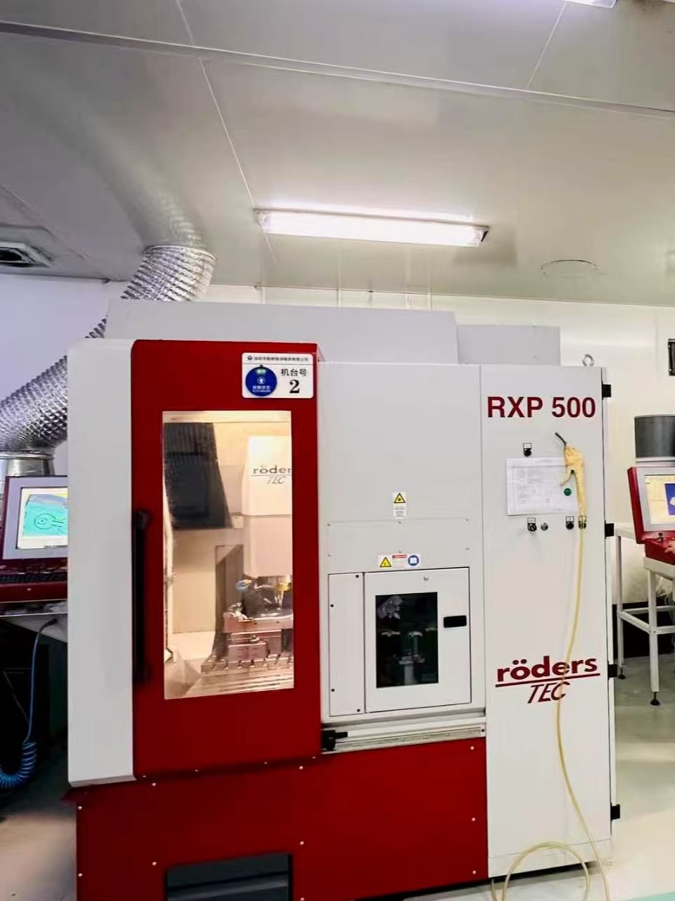
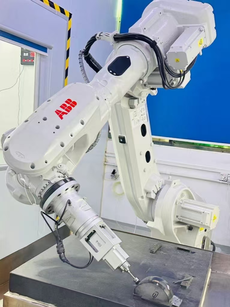
Machining capability is useful only when it supports the project risk
Camera lens mold-core projects need more than one machine or one finishing process. Drawing review, process selection, controlled finishing and inspection feedback need to support the same acceptance target.
What we need to review from your project
Providing the right project information before machining helps identify optical zones, local geometry risks, matching requirements and inspection references early.
Recommended files
- 2D drawing and 3D model
- Material and hardness requirement
- Cavity quantity
- Target surface / roughness requirement
- Critical optical zones and datum references
Useful supporting information
- Current defect photos or molded-part issues
- Visual / optical acceptance samples if available
- Required inspection report format
- Target project timing
- Replacement or matching requirements for existing inserts
Phone camera optical mold core questions
What is the MOQ?
There is no fixed MOQ. Single samples, replacement inserts, sample cavities and batch mold-core projects can all be evaluated from drawings.
Can you make spherical and aspheric lens mold cores?
Yes. Both can be evaluated from confirmed 2D / 3D data, material, optical surface requirement and inspection needs. See our dedicated Aspheric Mold Insert Machining page for the detailed process capability.
Can you make camera mold cores with micro-textures?
Yes, after drawing review. The final route depends on feature depth, minimum radius, material, tool accessibility and cavity structure.
Can you reach SPI A0?
For suitable materials and structures it can be evaluated. For optical projects, we recommend confirming the actual functional surface requirement together with the visual mirror requirement.
Can every project reach Ra ≤ 0.008 μm?
No. Achievable roughness depends on material, geometry, accessibility, machining route and the final acceptance standard.
What files are needed for quotation?
2D drawings and 3D files are preferred. STEP, IGES, X_T, DWG and PDF can be reviewed together with material, cavity quantity, surface requirement and target timing.
Can you provide dimensional and roughness reports?
Yes, based on the confirmed project scope. The inspection package can include key dimensional data, roughness data, visual records and customer-required formats.
What happens if the finished result does not meet the confirmed requirement?
The result should first be checked against the agreed drawing, inspection plan and acceptance standard. If a confirmed manufacturing issue comes from our process, the next correction step is arranged accordingly; other causes such as mold-trial conditions, resin, coating or drawing changes are analyzed separately.
Have a phone camera lens mold core project to evaluate?
Send the drawing, material, cavity quantity, target surface requirement and any current defect photos. We will first review the difficult optical zones, micro-features, datum relationships and inspection requirements before discussing the machining route.