
Diamond Turning Optical Mold Inserts
YISHUN provides diamond turning optical mold inserts for suitable rotational, concentric and plated optical structures. The goal is not simply a bright surface. It is to generate the required form, center relationship and surface finish in one controlled machining route.
A real diamond turning operation—from the rotating workpiece to finished mirror inserts.
These images outline a typical diamond turning workflow: a mirror insert mounted on the spindle, the cutting tool approaching the optical surface, and a matched set of finished inserts. Together they help explain how surface condition, tool access and rotational geometry are reviewed on this page.
What this real process evidence confirms
A mirror surface can still fail the optical insert.
Most problems begin before the finishing pass. The wrong material route, unstable pre-form, unclear effective aperture or undefined inspection method can create a surface that looks bright but does not function as intended.
Wrong material route
Direct diamond turning on an unsuitable ferrous surface can cause rapid tool wear, unstable cutting and schedule loss.
Center and feed-mark defects
Concentric marks, center artifacts or periodic texture may affect reflection, stray light or replication even when the surface appears smooth.
Profile lost after polishing
Uncontrolled post-polishing can reduce roughness while changing sag, groove shape, edge definition or the effective optical zone.
Datum mismatch
The optical surface may pass local measurement but still fail assembly if the center, flange, seating face or reference diameter shifts.
Diamond turning optical mold inserts for suitable optical geometry.
We do not force every insert into SPDT. Each drawing is reviewed for rotational symmetry, tool access, center geometry, substrate, plating, effective aperture and measurement feasibility.
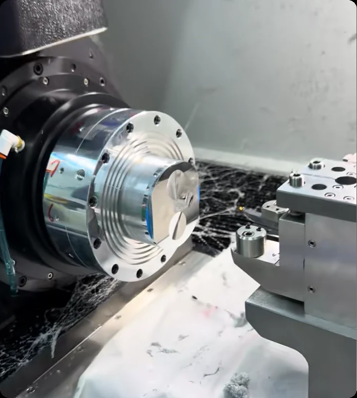
Rotational mirror optical inserts
Real close-up of a rotating mirror insert during precision turning, showing the optical surface and tool-access relationship.
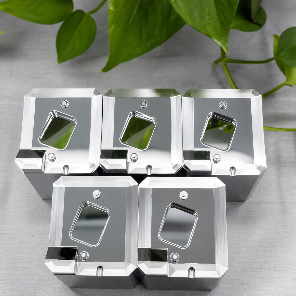
Multi-cavity mirror insert sets
Actual YISHUN product image showing repeated mirror-finish optical pockets, used to review cavity consistency and surrounding structural features together.
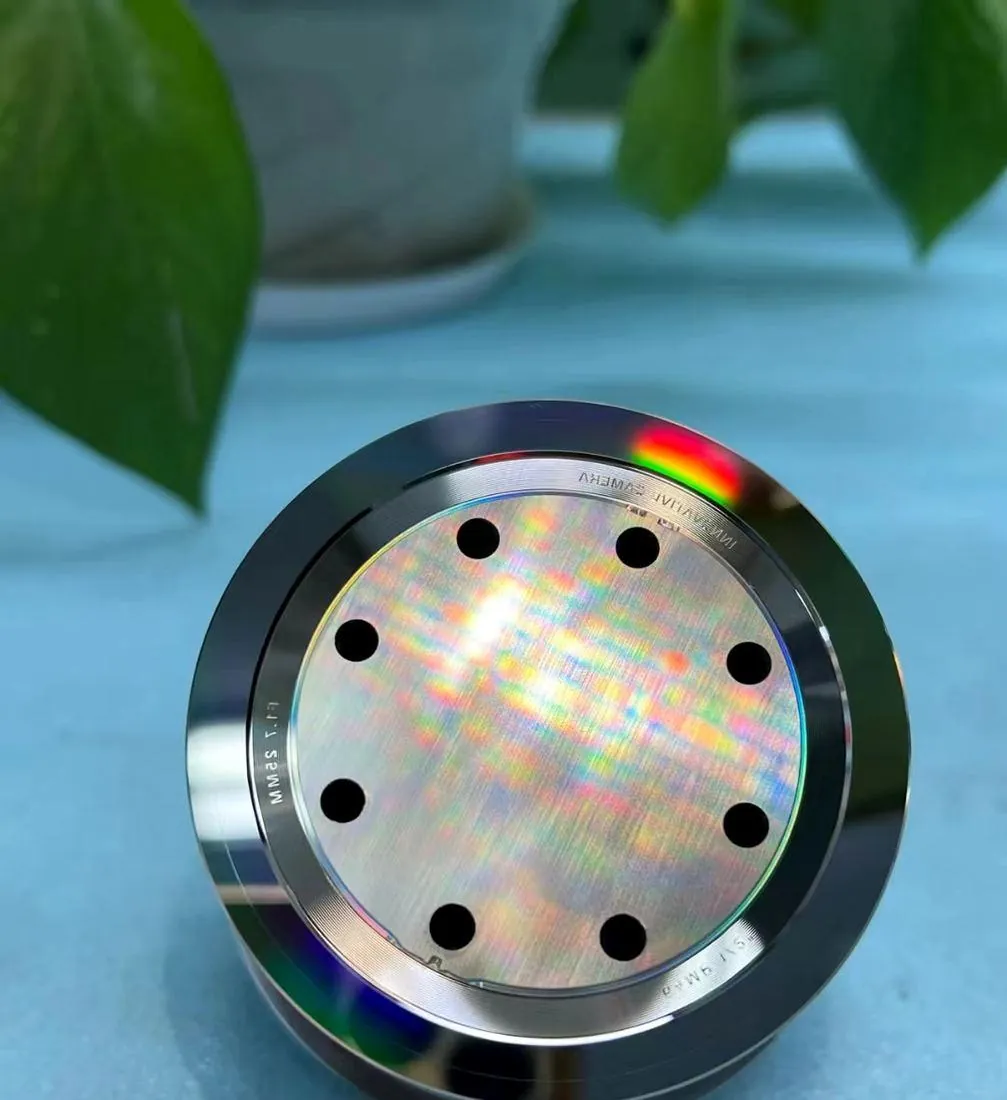
Circular inserts with multiple feature positions
Real circular insert image used to show rotational optical geometry where the mirror area, datum ring and multiple surrounding feature positions must be reviewed together.
Flat and annular optical surfaces
Qualified flat, ring-shaped and annular insert surfaces with specified datum and functional zones.
Nickel-phosphorus plated inserts
Substrates prepared and plated for a diamond-compatible optical cutting surface, subject to plating review.
Prototype and replacement inserts
New development inserts, validation parts and replacement inserts where matching and repeatability matter.
The cutting route starts with the substrate—not with the machine.
Diamond turning optical mold inserts requires a material surface that can be cut stably without damaging the tool or creating unstable texture. For steel-based tooling, the plating route and pre-form quality become part of the optical result.
From drawing review to measured optical surface.
The final pass is only one part of the route. The pre-form, datum, environment, tool condition and inspection plan determine whether the generated surface can be trusted.
Five details that decide whether the surface is truly usable.
Low roughness alone does not prove that a diamond-turned optical insert is ready for replication or assembly.
Center transition
The central region can reveal spindle, tool-setting or path problems that are not obvious elsewhere on the surface.
Feed-mark topology
Spacing and periodicity are reviewed because regular marks can influence reflection, scattering and appearance.
Edge and aperture boundary
Burrs, roll-off and overcut near the effective aperture can damage the usable optical area.
Plating integrity
The final optical pass depends on uniform, stable plating with sufficient remaining thickness and adhesion.
Datum-to-optical relationship
The optical surface must remain correctly located relative to the seating face, outer diameter, flange or assembly datum.
Repeatability between inserts
For replacement or multi-insert projects, matching the surface, datum and effective aperture is part of the machining plan.
Measure the function—not only the shine.
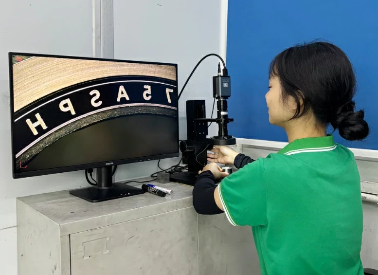
The inspection route is selected according to the drawing and the optical surface. Not every method is suitable for every geometry, coating or effective aperture.
Moore Nanotech machine used for diamond turning.
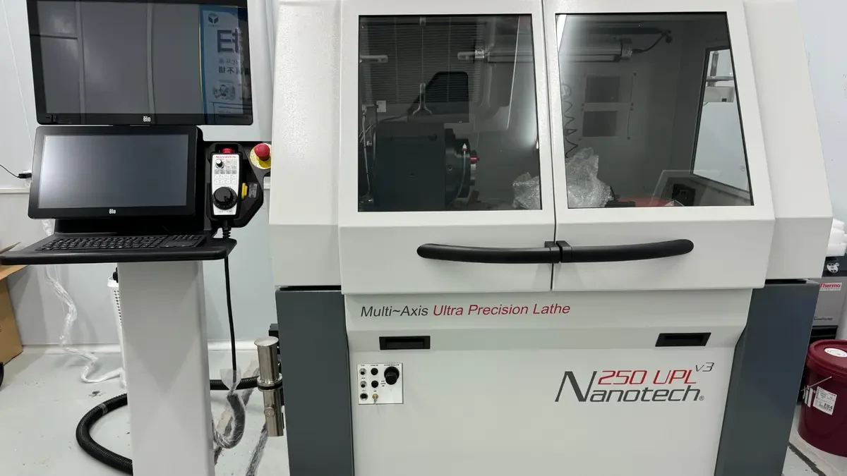
Confirm geometry, material and the Moore diamond turning route before production.
A useful quotation should reflect the real geometry, substrate, coating and acceptance plan. Incomplete specifications often create more risk than the cutting operation itself.
Questions buyers ask before selecting SPDT.
These answers define the project boundary before detailed drawing and process review.
Can you directly diamond turn hardened mold steel?
Usually not as a normal route. Ferrous materials cause rapid diamond tool wear. We may evaluate Ni-P plating or recommend ultra-precision milling, grinding and controlled polishing instead.
Does diamond turning eliminate polishing?
For suitable materials and applications, the optical surface may be generated directly. Additional polishing is not automatically beneficial and can change the profile or groove structure.
Can every freeform insert be diamond turned?
No. Rotationally symmetric and concentric geometry is the strongest fit. Non-rotational freeforms, deep sidewalls or blocked tool access may require five-axis machining or a combined route.
What causes visible rainbow or concentric marks?
Diamond-turned surfaces naturally contain periodic feed marks. Their spacing, height and optical effect depend on tool radius, feed, spindle behavior and surface requirements.
Can you rework an existing plated insert?
Possibly, but we must confirm the coating type, remaining thickness, damage depth, substrate condition and whether enough stock remains for correction.
Do you provide finished molded optical parts?
This page focuses on custom machining of optical mold inserts, masters and related tooling. Final molding or optical system design is not presented as the standard service scope.
Send the drawing before choosing diamond turning.
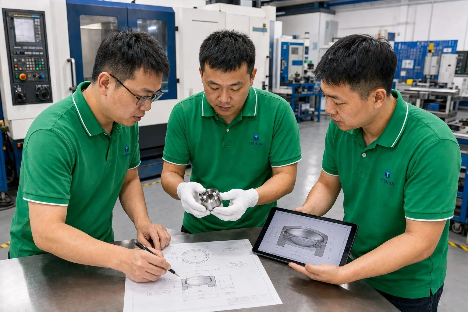
We will review geometry, substrate, plating, effective aperture, datum relationships and inspection requirements, then confirm whether SPDT or another ultra-precision route is more suitable.