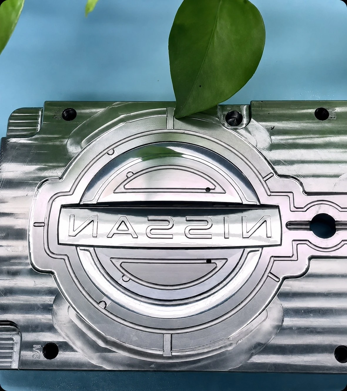
Industry Applications: Optical mold inserts for Automotive lighting, LED optics, headlamp reflectors, tail lamps, HUD reflectors, and interior ambient lighting components

We make custom optical mold inserts for automotive reflectors, lamp lenses, light guides, HUD parts, LED optical structures, and similar products. For these parts, surface quality directly affects how the final molded product looks and performs.

For this kind of product, a mirror surface cannot simply “look shiny.” A very fine tool mark, a slightly softened edge, or an uneven polishing mark may show up later on the molded part. Sometimes it becomes haze. Sometimes it affects the light pattern. Sometimes the customer only notices it during mold trials, which is usually the most frustrating stage.

That is why we keep five-axis mirror machining, ultra-precision machining, controlled polishing, and inspection reports in one workflow.

Customers only need to send us the drawing, 3D file, material, and required surface finish. We first look at the areas most likely to cause problems, then try to prevent issues before they appear.


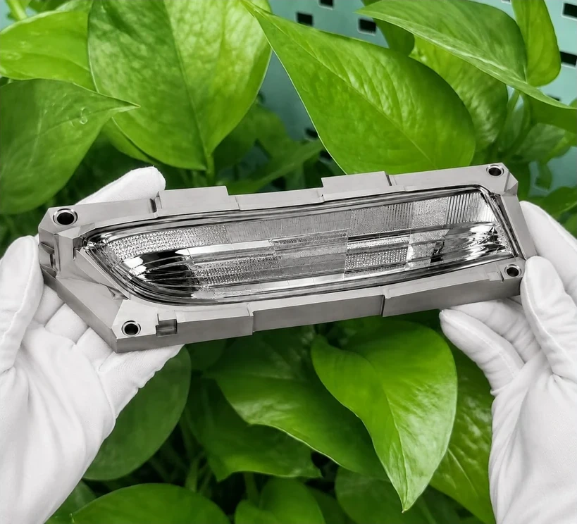
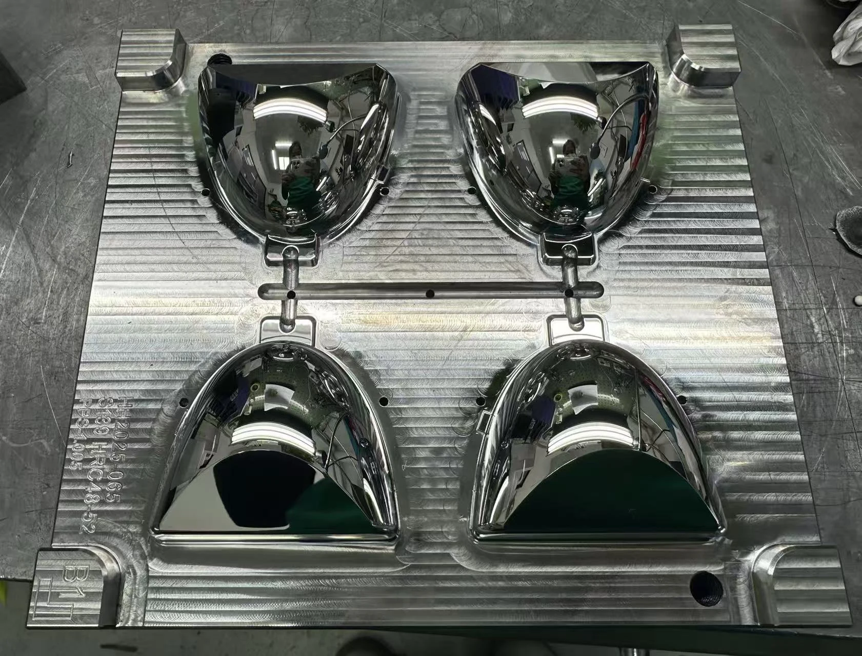
Custom mirror-polished automotive reflector mold insert with a deep curved optical cavity.

Quick Project Overview

Made to Your Drawings

We do not keep standard mold inserts in stock. Each product is arranged based on the customer’s drawing, cavity structure, material, surface requirement, and inspection requirement.

Mirror Surface Capability

When the material, structure, and process conditions are suitable, our mirror surface roughness can reach Ra ≤ 0.008 μm.

Complex Structure Machining

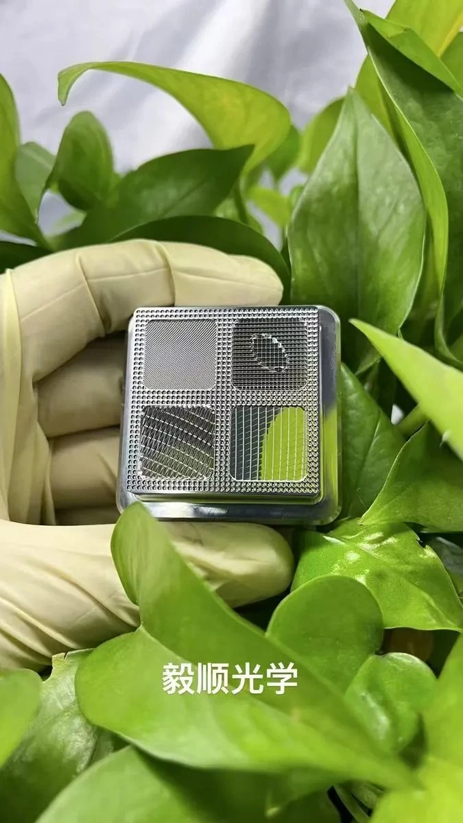
Freeform surfaces, curved reflectors, lighting patterns, ribs, grooves, optical textures, and multi-cavity mold inserts are all part of our regular work.

Inspection Report Support

After discussion, we can provide CMM reports, roughness reports, visual inspection records, and quality documents in customer-required formats.


Even a Mirror Surface That Looks Good Can Still Cause Problems

We have seen parts that looked very clean on the workbench. But under a stronger inspection light, or when checked with high-precision measuring equipment, there was still a very faint mark on the surface.

This is quite common.

On a normal high-gloss mold, a small issue like this may not matter much. But for an automotive reflector or lens mold, it can be different. Light is very sensitive to surface condition. Things that are not obvious at first can become more visible later.

Automotive optical mold inserts are usually more complicated than they look in a CAD drawing. There may be deep cavities, tight corner areas, sharp transitions, thin ribs, small radii, or curved reflector surfaces that are difficult to reach.

To be honest, many of the hardest areas look simple in the drawing.

A curved reflector surface may need machining from several angles. A small optical groove may need different polishing pressure from the surrounding area. And when it is part of a multi-cavity mold, it is not enough to make just one cavity look good. The other cavities also need to stay as consistent as possible.

We try to think about these issues early in the process instead of waiting until final polishing to fix them.


Our Products

We can customize automotive optical mold inserts for:

Some customers send complete drawings and inspection standards. Others only send a 3D file together with a photo of an existing molding problem. Both are fine.

In many cases, a close-up photo of the problem area is more useful than a long written explanation.

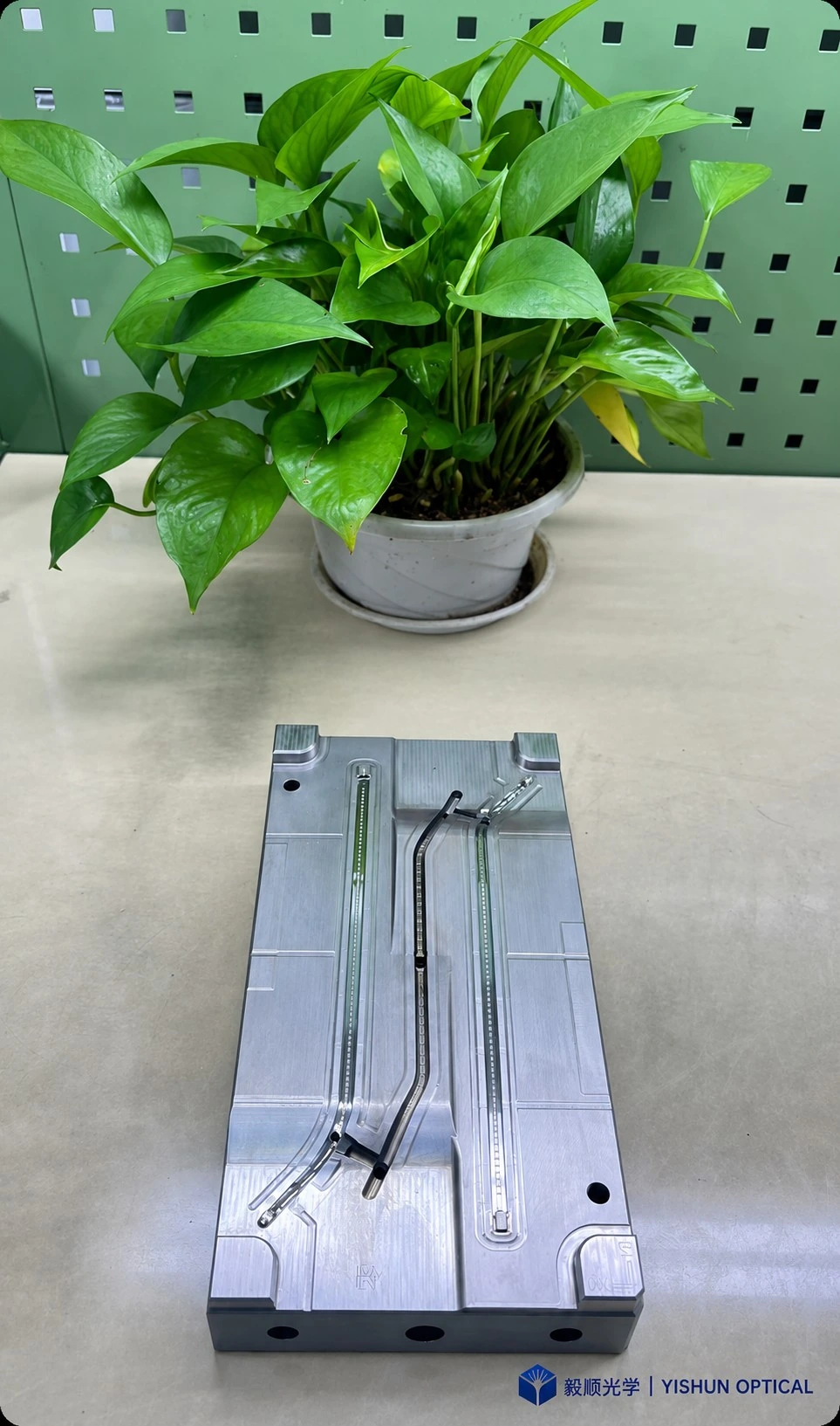
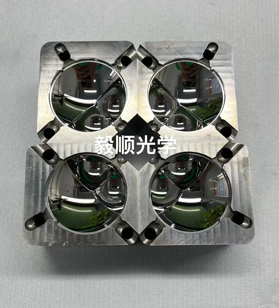
Four mirror-polished automotive optical mold inserts prepared for reflector and lighting component molding.
Four mirror-polished automotive optical reflector mold inserts with deep curved cavities

Why Customers Choose Us

Five-Axis Machining Is Better for Complex Optical Surfaces

Many automotive optical mold surfaces are not suitable for standard three-axis machining alone.

Deep reflector cavities, freeform surfaces, angled transitions, and complex optical cavities all need the cutting tool to approach from the right angle. Otherwise, the early machining marks become harder to remove, and later polishing takes much longer.

We use five-axis mirror machining to reduce unnecessary repeated clamping and keep the machining datum more stable.

Of course, this does not mean every part must use five-axis machining. Some need it. Some do not. We normally review the actual structure first, then decide on the most suitable machining route.


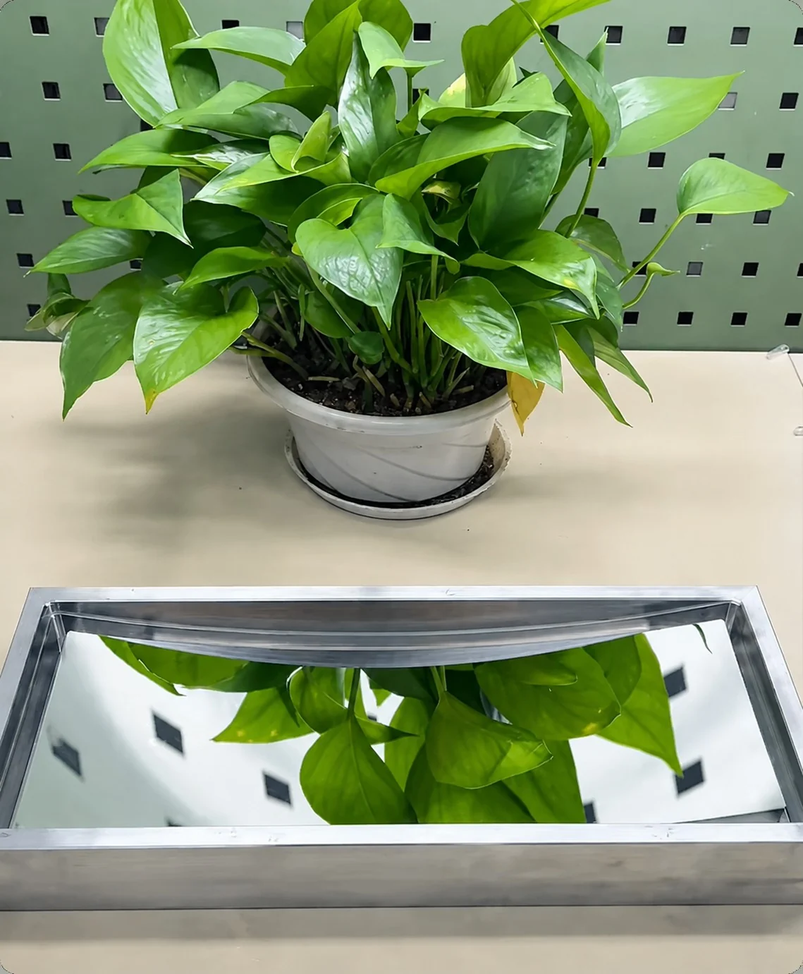
Five-axis machined automotive reflector mold core with mirror-finished optical surfaces

When Polishing, We Cannot “Polish Away” the Shape

Polishing is necessary. But too much polishing can also create problems.

This is something we pay close attention to.

A rounded edge may not look serious. A shallow groove may still look bright even when it is no longer very clear. But once these details are part of an optical surface, they can affect reflection, light diffusion, or light guiding in the molded part.

Our polishing process may include fine grinding, mechanical polishing, robotic polishing, manual finishing, and final visual inspection. However, we use different methods for different parts.

The actual process depends on the material, cavity depth, edge condition, required roughness, and how easy the surface is to access.

For SPI A0 requirements, we prefer to confirm the appearance standard and roughness requirement together. Some parts can have a very low roughness value but still not look good enough under direct light. This requires proper operation and professional judgment.


Ribs, Grooves, and Optical Textures Need Extra Attention

Automotive lighting molds often include details that can be easily affected during polishing.

Small ribs. Narrow grooves. Prism structures. Fine reflector patterns. Deep corner areas.

These areas do not only need polishing. More importantly, they need to keep their original geometry.

For this type of product, we plan machining and polishing around the critical features instead of treating the whole cavity as one large mirror surface.

Sometimes one tiny part needs more work time than the rest of the mold core. This happens a lot.

This type of work is common in:


Inspection Reports  Make Customer Approval Easier

A polished mold insert should not be judged only by photos.

For overseas projects especially, inspection data matters. It helps engineering, purchasing, and quality teams work from the same standard.

Depending on the project, we can provide:

Our inspection capability includes Zeiss CMM equipment, Mitutoyo roughness testers, Zygo white light interferometers, microscopes, and visual inspection tools.

At the beginning of a project, we prefer to make things clear: what can be measured, what needs visual inspection, and what may still need to be confirmed through mold trials. It saves a lot of unnecessary trouble later.


Technical Specifications

ItemTypical Capability / Requirement
Product TypeCustom automotive optical mold inserts
Main ApplicationsHeadlamp reflectors, tail lamps, LED optics, HUD reflectors, light guides, lens molds
Surface RoughnessRa ≤ 0.008 μm when material, structure, and process conditions are suitable
Surface RequirementSPI A0 visual mirror finish or customer-defined surface standard
Typical Finished AccuracyUp to ±0.005 mm for selected automotive optical mold projects
Optical Surface ControlBased on confirmed drawings, CAD data, P/V requirements, and inspection methods
Processing MethodFive-axis mirror machining, ultra-precision machining, fine grinding, mirror polishing
Spindle TechnologySome ultra-precision machines use air spindles
Maximum Spindle SpeedUp to 60,000 rpm on selected equipment
Reference Automotive Project SizeUp to 500 × 460 × 240 mm
Processable MaterialsMold steel, stainless mold steel, tungsten carbide, SiC, and other compatible customer-specified materials
Inspection EquipmentZeiss CMM, Zygo interferometer, Mitutoyo roughness tester, microscope inspection
Quality DocumentsAvailable based on the inspection plan agreed by both parties
MOQQuoted by project; samples and batch orders can both be evaluated
OEM / ODMOEM manufacturing and process support available

Final capability needs to be confirmed after drawing review. Machine positioning accuracy is not the same as finished part tolerance. Final acceptance is based on the drawing and inspection plan agreed by both parties.


Common Automotive Optical Applications

Headlamp Reflector Mold Inserts

Headlamp reflector molds often have deep curved areas and light distribution surfaces. It is not always easy to polish them evenly.

We can support custom machining for reflector cavities, projector modules, LED lamp chambers, and related optical structures. The main focus is usually surface consistency, edge control, and keeping the original geometry during polishing.

Tail Lamp and Signal Lamp Molds

Tail lamp parts may look simple from the outside, but the mold often contains optical details, decorative textures, reflective areas, and many small transitions.

We can provide custom mirror mold cores and cavities for transparent, colored, and decorative automotive optical components.

HUD reflector molds

HUD reflector molds usually involve freeform surfaces and large visible optical areas.

These projects need careful control during machining and polishing. Based on confirmed drawings and inspection requirements, we can provide HUD reflector inserts, prototype molds, and mirror-finished optical hand plates.

Automotive Interior Lighting Components

More and more vehicle interiors now use illuminated trims, light guides, decorative optical covers, and ambient lighting structures.

We also work on these projects. Some are mainly about appearance. Others are more sensitive to light distribution. We try to separate these points during the early review stage.


Our Factory and Technical Team

Yishun Optical has focused on high-precision mirror mold solutions for around 20 years. Our technical team has about 50 people, covering drawing review, CNC programming, five-axis machining, ultra-precision machining, polishing, grinding, inspection, and project coordination.

We are not a large general machining factory that makes every kind of part. Our main work is focused on projects where surface control needs extra attention: mirror cavities, optical inserts, freeform surfaces, and difficult polishing areas.

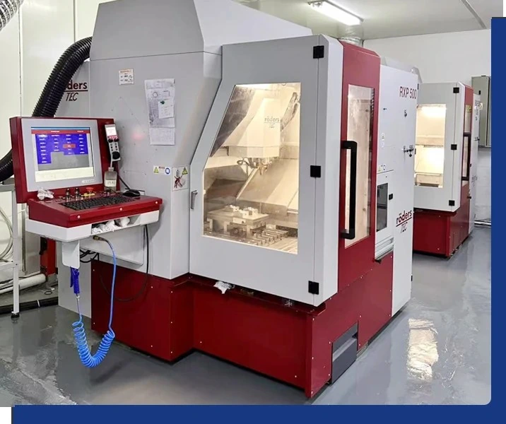
Our main equipment includes ultra-precision single-point diamond turning equipment, Toshiba ultra-precision nano machining centers, Röders mirror machining centers, optical polishing robots, automatic mirror polishing equipment, optical plane grinders, Zeiss measuring equipment, Zygo interferometers, and Mitutoyo roughness testing equipment.

Some Toshiba ultra-precision equipment can reach positioning accuracy of 0.001 mm and repeat positioning accuracy of 0.0005 mm.

For us, the best proof is still the actual part itself: how the surface looks, what the inspection report shows, and how the customer’s mold trial turns out.


How We Handle an Order

1. Drawing Review

We first review the drawing, 3D model, material, required surface finish, key optical areas, and the inspection documents needed.

Sometimes the drawing is enough. Sometimes we also need to understand the molding resin, cavity layout, or final optical function. That is normal.

2. Process Planning

Next, we decide how the part will be clamped, machined, polished, measured, and protected.

At this stage, we usually identify the areas that may create problems later: deep cavities, sharp edges, narrow grooves, freeform surfaces, and difficult polishing areas.

3. Precision Machining

We choose suitable equipment based on the part geometry and material.

For complex reflectors and optical surfaces, we may use five-axis machining or ultra-precision air spindle machining. For simpler structures, a more direct machining route may be enough.

4. Fine Grinding and Pre-Polishing

This stage removes machining marks from the previous process and prepares the surface for final mirror polishing.

It sounds simple, but for curved reflectors and fine optical structures, this is often the stage where the original geometry needs the most protection.

5. Mirror Polishing

Based on the actual surface condition, we combine mechanical polishing, robotic polishing, and manual finishing.

We do not only focus on making the part look brighter. The shape also needs to stay correct.

6. Inspection

We check critical dimensions, roughness, visual condition, and other quality points agreed by both parties.

For some projects, a roughness report is enough. For others, customers may also need CMM data, optical surface form data, or detailed photos. These can all be discussed before production starts.

7. Packing and Shipment

Before shipment, parts are cleaned, protected against scratches, packed for international transport, and supplied with the agreed documents.


FAQ

What is your MOQ?

We do not have a fixed MOQ because every project is made to order.

We can evaluate single samples, prototype inserts, replacement cavities, small trial runs, and batch orders.

Can You Make OEM Automotive Optical Mold Inserts?

Yes. We can manufacture according to customer drawings, CAD files, material requirements, surface targets, and inspection standards.

Can You Provide DFM Feedback?

Yes. Before production, we can review polishing accessibility, machining feasibility, edge protection, material selection, and inspection arrangements.

Sometimes a small design adjustment can make later polishing much easier. If we see something like that, we will mention it directly.

What Do You Need for a Quotation?

Please provide a 2D drawing, 3D model, material requirement, surface requirement, tolerance, quantity, cavity information, and preferred delivery date.

Photos of the existing mold or problem areas are also very helpful.

Do You Provide Inspection Reports?

Yes. Based on the agreed inspection plan, we can provide CMM reports, roughness reports, visual inspection records, key dimension reports, and customer-required documents.

Can You Meet SPI A0 Requirements?

For projects with suitable materials and structure, we can support SPI A0 visual mirror finish requirements.

Still, we recommend confirming roughness, visual standards, and optical function requirements together before production. This helps avoid different understandings later.

What Is the Typical Lead Time?

Lead time depends on part size, material, complexity, surface requirement, inspection scope, and quantity.

After receiving the drawing and completing the review, we can provide a more realistic production schedule.

What After-Sales Support Do You Provide?

If customers find issues during mold assembly or mold trials, they can send us photos, measurement data, or short videos. We will review the case based on the confirmed drawing and quality requirements.


Request a Custom Quote

Send us your drawing, 3D model, material requirement, target surface finish, and estimated quantity.

Based on the project, we can provide:

Request a Drawing Review
Get a Sample Quote
Submit Your Automotive Optical Mold Requirement

Start Your Project With A Free Quote

Our professionals are available to talk you through each of our offerings. We’ll be sure to answer you within 24 hours. Fill out the information below with as much detail as possible, and we’ll get back to you promptly.