
A good Fresnel lens starts with more than a correct optical design. During manufacturing, small changes in facet angle, groove depth, pitch, center position, or step geometry can change the final light pattern.
At Yishun Optical, we provide custom ultra-precision Fresnel lens mold insert machining. Our service covers mold cores, inserts, optical masters, metal prototypes, replacement inserts, and microstructured optical surfaces. We work from your drawings, material, optical requirements, and inspection standard. Our goal is to help you reduce optical defects, repeated mold trials, polishing damage, and differences between cavities.
Product Introduction
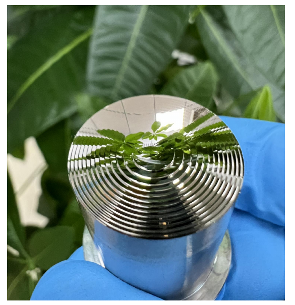
A Fresnel lens divides a conventional curved optical surface into narrow concentric or linear facets. This reduces thickness and weight while maintaining the required focusing, collimating, diverging, or light-distribution function.
Uses: Fresnel structures are used in LED and automotive lighting, projection and display systems, PIR and infrared sensors, wearable devices, compact optical modules, solar concentration, industrial inspection, and laser equipment.
Most customers ask us to machine a Fresnel lens mold insert or master for later injection molding, compression molding, or replication. We can also evaluate directly machined metal optical prototypes when the material is suitable.
Machining Process:
Depending on the material, hardness, Fresnel profile, and optical requirements, we may use single-point diamond turning, ultra-precision milling, or five-axis mirror machining.
The active Fresnel surface is directly machined to achieve the required mirror finish while maintaining the designed groove pitch, facet angle, step height, sharp edges, and optical center.
We determine the final machining route after reviewing the drawing, critical dimensions, target form accuracy, surface roughness, and inspection standard. After machining, we inspect the key dimensions, form accuracy, groove geometry, and surface quality according to the agreed requirements.
.png)
.png)
How Our Equipment Supports Fresnel Lens Machining
| Process Step | Key Equipment | What It Helps Us Control |
|---|---|---|
| Ultra-Precision Cutting | Moore 250UPL v2; Toshiba UVM700C(H), UVM450D(H), UVM450C(H) | Groove profile, form accuracy and surface finish on suitable materials |
| High-Speed 5-Axis Machining | Röders RPT600DSH, RXP500DS/DSC; Beijing Jingdiao 5-axis machining centers | Free-form transitions, datums, microfeatures and complex insert geometry |
| Controlled Optical Finishing | Six-axis optical polishing robot; automatic mirror polishers; optical surface grinders | Tool-mark removal and mirror preparation while protecting critical geometry |
| Dimensional Inspection | ZEISS CMM | Datums, dimensions, position and geometric relationships |
| Surface Inspection | Mitutoyo SJ-410; ZYGO NewView 9000; microscopes | Roughness, 3D topography, local defects and microfeatures |
| 3D Comparison | ZEISS blue-light scanner | Whole-surface deviation and geometry comparison where appropriate |

Technical Parameters
| Item | Typical Capability / Requirement |
|---|---|
| Service | Build-to-print custom ultra-precision Fresnel lens mold insert machining for cores, masters, prototypes, replacement inserts, and microstructured surfaces |
| Structures | Circular, linear, cylindrical, off-axis, segmented, and freeform-plus-Fresnel designs |
| Materials | S136 and customer-specified mold steels; aluminum, copper, brass, electroless-nickel-plated substrates, and other materials after review |
| Processes | Single-point diamond turning, ultra-precision machining, three-axis/five-axis milling, mirror machining, precision grinding, and controlled polishing |
| Selected Project Size | Up to 650 × 300 mm; final capacity depends on part height, fixture, weight, and feature position |
| Selected Form Accuracy | PV 0.15 μm achieved on selected Fresnel mold projects under suitable conditions |
| Selected Surface Roughness | Ra 0.005 μm achieved on selected Fresnel mold projects under suitable conditions |
| Dimensional Accuracy | Up to ±0.001 mm for selected optical mold projects; confirmed after drawing review |
| Inspection | White-light interferometry, roughness measurement, CMM, microscope, blue-light scanning, or customer-defined methods |
| Files | STEP/STP, IGES/IGS, X_T, DWG/DXF, PDF, and other common formats |
| Order Type | Prototype, sample insert, replacement insert, validation batch, or multi-insert project |
These are selected project capabilities, not an automatic guarantee for every part. We confirm final tolerance, form, roughness, size, and inspection after reviewing the application.
Precision and Acceptance Standards
We normally work to the customer’s approved drawing and inspection plan. When applicable, surface texture may reference ISO 10110-8:2019 or the ISO 21920 series, while surface imperfections may follow ISO 14997:2017. Fresnel pitch, depth, facet angle, vertex radius, optical center, form error, and measurement positions must still be defined separately because Ra alone does not control the complete optical geometry.
Fresnel Products We Can Customize
- Circular, linear, and cylindrical Fresnel lens mold inserts
- LED and automotive lighting Fresnel optics molds
- PIR sensor and infrared Fresnel lens mold inserts
- Projection, condenser, and illumination Fresnel molds
- Wearable-device and compact optical-module structures
- Fresnel reflector molds and beam-shaping masters
- Hybrid freeform and Fresnel optical surfaces
- Large-area masters after manufacturability review
- Metal prototypes, sample cavities, and replacement inserts
If your product is not listed, send us the drawing. We can evaluate it from the profile, material, aperture, and acceptance standard.
Customer Pain Points and Our Solutions
1. The CAD Profile Is Correct, but the Machined Groove Is Not
Pitch, depth, facet angle, vertex radius, and step height affect one another. Tool compensation, thermal drift, or accumulated pitch error can change the optical result even when the surface looks clean.
Our solution: We review the profile, optical axis, tool access, and radius compensation before machining. We define datums and agree on the groove dimensions and form values that need inspection.
2. Polishing Improves Brightness but Damages the Shape
Uncontrolled polishing can round groove peaks, make narrow steps shallow, and change facet angles. The insert may pass a visual mirror check but fail optical testing.
Our solution: We reduce polishing through precision machining. Where finishing is needed, we use local contact and controlled allowance to protect peaks, narrow grooves, the center feature, and transition areas.
3. Tool Marks Cause Rings, Haze, Ghost Images, or Hot Spots
Periodic tool marks may act like an unwanted optical pattern. Burrs, torn edges, and uneven roughness can scatter light or create non-uniform brightness.
Our solution: We match tool geometry and cutting parameters to the material and profile, monitor tool condition, and inspect for periodic behavior. Any post-process must improve the surface without removing the Fresnel geometry.
4. The Optical Center Does Not Match the Mechanical Datum
A correct Fresnel pattern can still fail in assembly if its center is offset from the outside diameter, mounting features, or mold datum. The result may be asymmetric light or difficult alignment.
Our solution: We confirm optical and mechanical datums before programming. Where possible, features are machined in one setup or transferred through a controlled datum method. Center position and runout are included in the inspection plan when critical.
5. Large Surfaces Change from Center to Edge
Temperature, clamping stress, machine motion, material stability, and tool wear may create form or pitch differences across a large aperture.
Our solution: We plan fixture support, machining sequence, thermal control, tool checks, and measurement coverage. Inspection covers the center, middle, edge, and critical transition zones instead of one small area.
6. Multi-Cavity Inserts Give Different Optical Results
Two inserts may pass basic dimensional inspection but still produce different brightness or beam distribution because of small differences in groove geometry, surface marks, or datum transfer.
Our solution: We use common process references, tool strategy, setup logic, and inspection methods across the set. Cavity-to-cavity comparison helps reduce sorting, mismatched assemblies, and repeated adjustment.
7. Customer and Supplier Use Different Inspection Definitions
Ra, RMS, PV, form error, and visual appearance describe different conditions. Results also change with scan length, filter, measurement position, datum, and instrument.
Our solution: Before production, we confirm what will be measured, where it will be measured, the acceptable method, and the report format. If final optical performance controls acceptance, we also ask how the molded lens will be tested.
Why Work with Yishun Optical?
We Identify Risk Before Material Is Removed
We review groove access, center geometry, smallest radius, facet direction, material, aperture, surrounding features, replication process, and inspection. Finding a conflict early can prevent a complete re-machining cycle.
We Match the Process to the Material
A plated, diamond-turnable insert and a hardened steel insert should not follow the same route. We select diamond turning, ultra-precision milling, five-axis machining, grinding, or controlled polishing according to the workpiece. This reduces unnecessary operations and tool-wear risk.
We Protect Both Surface Finish and Groove Fidelity
A mirror finish helps only when the Fresnel geometry remains correct. We reduce tool marks while protecting facet angles, step heights, sharp transitions, and the optical center. This can improve the molded lens without changing the designed light path.
We Support Prototypes, Repairs, and Replacement Inserts
You may need one prototype, one validation cavity, or one replacement insert rather than a complete mold. We can review these custom projects and help reduce rework, optical scrap, extra trials, sorting, and approval delays.
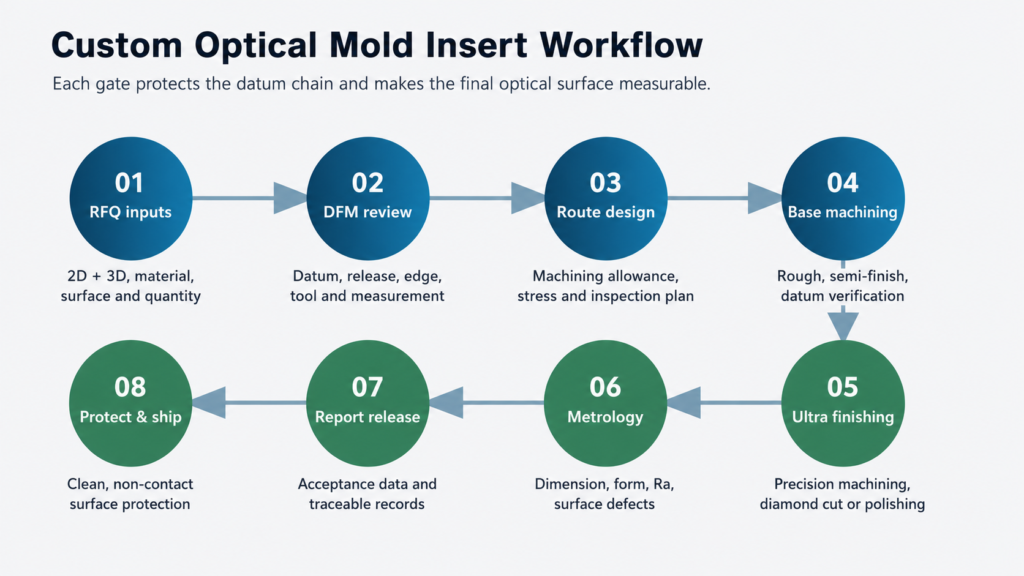
During quotation, we explain the proposed route, key risks, inspection points, and information still needed. During production, agreed requirements stay tied to the drawing and process plan. At delivery, the available inspection records are matched to the accepted items. This gives your engineering, sourcing, and quality teams a clearer basis for approval, troubleshooting, and repeat orders.


What We Need from You
- 2D drawing and 3D model
- Material, hardness, heat treatment, and coating
- Optical aperture and non-optical areas
- Pitch, depth, facet angle, smallest radius, and center structure
- Critical dimensions, PV/form requirement, roughness, and appearance standard
- Inspection method, report format, quantity, and schedule
- Final application, molding resin, and replication process
If the specification is incomplete, send the available model, sample photos, defect photos, or optical test results. We can help identify missing manufacturing information.
FAQ
Do you manufacture finished plastic Fresnel lenses?
Our main service is machining Fresnel mold cores, inserts, masters, prototypes, and optical tooling. For production lenses, send the resin, quantity, and standard so we can confirm whether molding is within our scope or requires a partner.
Which materials can you machine?
We can evaluate mold steels, aluminum, copper, brass, electroless-nickel-plated substrates, and other materials. Diamond turning is normally used for suitable non-ferrous or plated surfaces; steel may need milling, grinding, polishing, or a combined route.
Can every part reach PV 0.15 μm and Ra 0.005 μm?
No. We achieved these values on selected Fresnel mold projects. The result depends on material, aperture, profile, size, tool access, fixture, and measurement. We confirm the project target after review.
How do you protect sharp groove edges?
We minimize polishing through precision machining, then control finishing contact, allowance, pressure, and direction around peaks, narrow grooves, steps, and center features.
Can you machine a large Fresnel mold?
Selected projects have reached 650 × 300 mm. Feasibility depends on height, weight, clamping, feature location, aperture, and inspection access.
Can you repair or remake an existing insert?
Often, yes. We check remaining allowance, datum recovery, and whether the optical profile is measurable. We will explain whether re-machining, local restoration, or replacement is safer.
What reports can you provide?
Depending on the project, we can discuss dimensional, CMM, roughness, white-light interferometer, microscope, and scanning records. Positions, filters, datums, and formats should be agreed first.
What is the lead time?
Lead time depends on material, geometry, size, tolerance, finishing, and inspection. After drawing review, we provide a clear process plan and delivery estimate.
Let’s Review Your Fresnel Lens Project
If groove accuracy, optical surface quality, large-area form, or cavity consistency is delaying your project, send us the drawing. We will review the manufacturing risks and recommend a practical route.
For a faster quotation, include your 3D model, 2D drawing, material, aperture, target PV/Ra, inspection method, quantity, and required delivery date.
Talk with us about custom ultra-precision Fresnel lens mold insert machining before the next mold trial.