Automotive Light Guide & Ambient Lighting Mold Solution
If the light line looks uneven, the transition is unstable, or small optical features lose definition after finishing, polishing more is usually not the real solution.
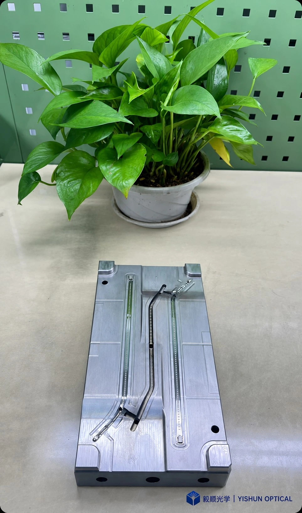
For automotive light-guide and ambient-lighting inserts, the real machining difficulty is controlling the complete optical path: long-channel geometry, local transitions, groove or prism definition, surface continuity, and datum matching to the mold structure.
Ultra-Precision Machining Experience
More than two decades focused on difficult ultra-precision machining projects, including optical mold inserts and appearance-critical components.
Senior Technical Staff
More than 30 employees have over 20 years of practical experience, supporting judgment, process control and problem-solving on challenging projects.
Optical Components & Precision Inserts
From long light-guide inserts to micro-structured optical parts, Yishun has handled a broad range of ultra-precision optical projects.
Stabilizing an automotive light-guide insert with uneven optical performance
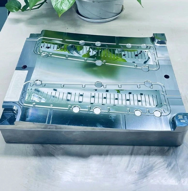
An automotive lighting customer approached Yishun after repeated trial problems with a light-guide insert. Surface roughness measurement looked acceptable, but the final molded part still showed visible brightness inconsistency along the light path.
Instead of treating the issue as a simple polishing problem, our engineers reviewed the complete insert structure as one connected optical path.
Where these inserts are used and why they are difficult
Automotive ambient-lighting inserts often combine long optical paths, local transition zones, and small functional structures in one component. That is why the machining strategy has to be more precise than a normal appearance insert.
- Typical applications: dashboard ambient light guides, door-trim light guides, center-console light pipes, and illuminated decorative strips.
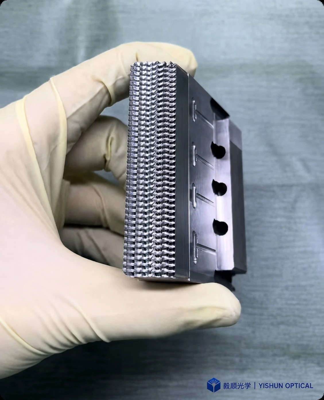
- Typical structures: long straight channels, curved light-guide paths, local prism or groove zones, and replacement inserts that must match existing mold references.
- Main customer concerns: uneven light output, visible machining traces, blurred micro-features, unstable transition zones, and mismatch during replacement or assembly.
- Main machining goal: deliver an insert that supports more stable optical behavior before mold trial, not just a surface that looks bright in isolation.
What we pay attention to during machining
Long-path geometry
- Surface continuity along the optical path
- Height and form relationship between zones
- Control of local curvature or path changes
Fine feature definition
- Protection of grooves, prisms and small edges
- Avoiding over-rounding during finishing
- Maintaining local structure clarity
Surface condition
- Suppressing visible tool marks
- Controlling local waviness and trace patterns
- Matching the finish to the real optical zone
Transition zones
- Managing changes between functional sections
- Controlling local boundary behavior
- Reducing abrupt appearance change
Datum relationships
- Reference surfaces and locating logic
- Assembly matching to the mold structure
- Replacement insert consistency
Repeatability
- Stable process route
- Consistency across repeat inserts
- Controlled review before delivery
Production environment and machining support behind the project
Customers often want to know whether the supplier can really support consistent optical machining in production. The images below show part of Yishun’s real production and technical support environment.
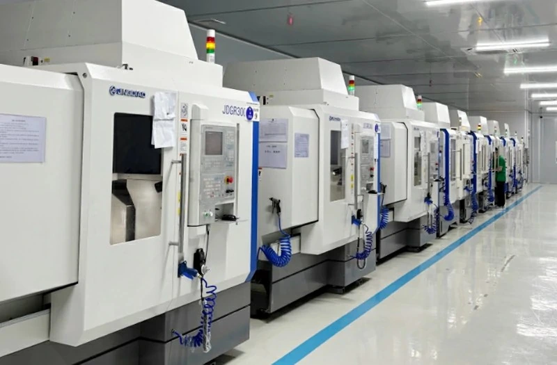
Production Workshop
Clean and organized machine layout helps support stable process execution and repeatability for optical mold projects.
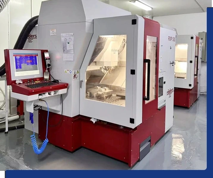
Five-Axis Mirror Machining Equipment
Complex optical inserts often require stable multi-angle machining capability to control geometry, transitions and surface condition together.
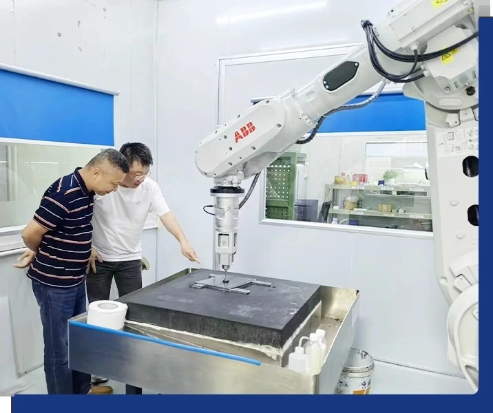
Technical Support & Verification
Process review and in-process verification are important when the customer’s real risk is optical instability rather than a simple dimension issue.
Reference capability for automotive optical insert projects
| Category | Reference capability / project focus |
|---|---|
| Typical tooling | Automotive light-guide mold inserts, ambient-lighting optical inserts, long optical channels, structured optical inserts, replacement inserts. |
| Machining methods | Five-axis mirror machining, ultra-precision machining, and controlled surface finishing selected according to the real structure and material. |
| Surface roughness | Ra ≤ 0.008 μm has been achieved on selected automotive optical mold projects under suitable material, structure and process conditions. |
| Finished accuracy | Up to ±0.005 mm on selected automotive optical mold projects; final tolerance depends on the drawing and inspection scope. |
| Reference project size | Automotive optical mold project reference up to 500 × 460 × 240 mm. |
| Inspection focus | Critical dimensions, datum relationships, local feature condition, surface roughness, and the agreed optical-surface requirements. |
Typical insert structures we can review
Long Linear Light Guide Insert
For long narrow optical paths where channel geometry, transition control and datum stability all affect the final light line.
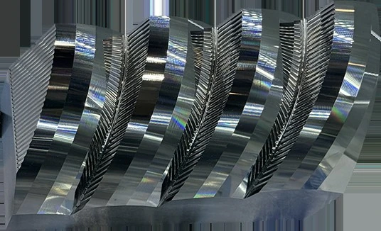
Multi-Zone Light Guide Insert
For inserts that combine multiple path sections or local functional regions in one part, requiring more careful zone-to-zone consistency.
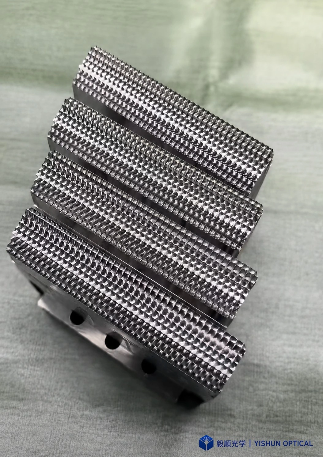
Prism / Groove Optical Insert
For inserts with dense optical structures where small grooves, prisms or directional features need to stay clear after finishing.
Replacement or Matching Insert
For new inserts that must still match an existing mold base, reference system or surrounding optical structure.
What customers usually struggle with, and how we approach it
How we evaluate the insert before delivery
Optical zone continuity
Check whether the key functional surfaces and transitions remain consistent through the complete optical path.
Feature condition
Review grooves, prisms, edges and other fine optical structures that should not be softened by correction or finishing.
Datum and assembly matching
Confirm the relationship between functional surfaces and the mold references that control installation and replacement.
Surface condition in critical areas
Review local marks, waviness, polishing traces and any appearance-critical zones that could show under illumination.
What we need before machining starts
Basic project data
2D drawing, 3D model, material, hardness and any mold-base matching information.
Optical zone definition
Clear marking of light-entry, transmission, exit and appearance-critical zones whenever possible.
Known problem description
If the current mold already has issues, photos or trial feedback help us judge the likely root cause faster.
Critical requirement alignment
Finish expectation, dimension priorities, inspection scope and replacement-matching requirements should be clarified early.
Review support
If needed, we can help identify which areas are likely to be functional optical risks before production starts.
What machining inspection can and cannot confirm on its own
But the final lighting effect of a light-guide part also depends on part design, resin behavior, molding process and assembly conditions. If the customer has special lighting targets or appearance standards, those should be defined in the project review stage rather than assumed later.
Documents that help us review the project more accurately
- 2D drawing and 3D model (STEP / IGES / PDF)
- Material and hardness requirement
- Critical dimensions and datum references
- Optical-zone markings or notes
- Required finish or appearance standard
- Existing defect photos or sample images
- Mold-trial feedback if the issue is already known
- Replacement matching or assembly constraints
Frequently asked questions
These are the questions customers most often ask before sending drawings for this kind of insert.
Can you machine long automotive light-guide mold inserts with complex optical paths?
Yes. We can review long automotive light-guide inserts based on the actual length, structure, material, optical zones and tolerance requirements of the project.
What are the main machining challenges for automotive light-guide inserts?
The main challenges usually include long optical-path control, unstable transition areas, visible machining traces, fine-structure protection, and consistency between functional optical zones.
Does a lower Ra value always mean better optical performance?
No. A lower Ra value only describes one part of surface condition. Optical performance can also be affected by form accuracy, reflection continuity, feature definition and the quality of local transitions.
Can you help analyze an existing mold insert that already has lighting problems?
Yes. If you can provide drawings, photos, samples or mold-trial feedback, we can review whether the problem is more likely related to geometry, finish, optical structures or insert matching.
What materials can you machine for automotive light-guide inserts?
We can review commonly used optical mold materials according to the application requirements, including hardened steel and other mold materials suitable for automotive optical inserts.
Can you produce replacement inserts that match an existing mold?
Yes. For replacement projects, we pay close attention to datum references, assembly relationships and critical optical areas so the new insert can match the existing mold system more reliably.
How do you control the quality of automotive optical inserts before delivery?
Before delivery, we review critical dimensions, reference surfaces, optical areas, fine structures, surface condition and the agreed inspection requirements according to the project scope.
What information should we provide before requesting a quotation?
We recommend providing 2D drawings, 3D models, material requirements, optical surface requirements, critical tolerances, and any known problems or trial feedback. This helps us review the project more accurately before machining starts.
If your automotive light-guide insert is difficult to stabilize, we can review the real machining risks first
Send the drawing, known problem areas and any trial feedback you already have. We can review the optical path, fine-feature zones, matching logic and likely machining risks before production starts.