Microfluidic Chip Mold Inserts for Precision Micro-Feature Machining
Microfluidic inserts are not difficult simply because the features are small. The real challenge is keeping channel geometry, edge definition and functional surface quality stable at the same time.
Yishun focuses on the precision mold insert side of the project, helping customers review difficult geometry before machining and reduce avoidable correction later.
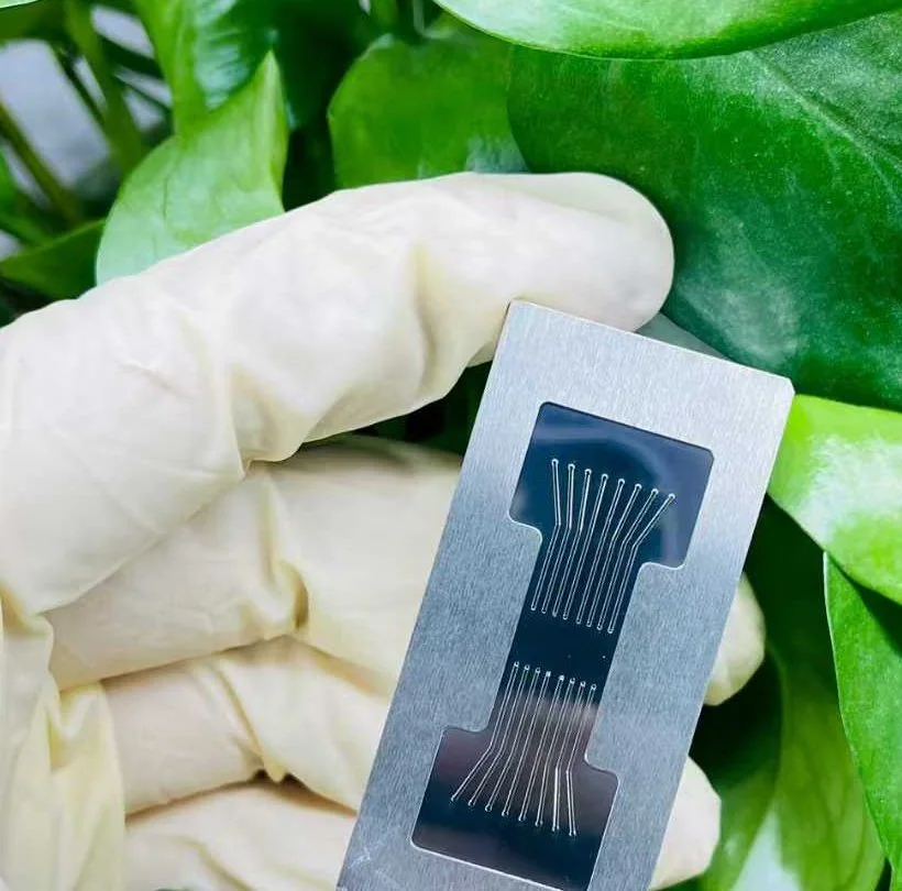
Three risks usually matter more than the overall part size
For microfluidic molds, one small local deviation can affect how the feature performs later. We therefore review the most sensitive geometry first, not just the nominal dimensions.
Rounded edges, local form change or over-finished surfaces may create problems even when the part looks visually smooth.
Microchannel accuracy
Width, depth and local profile need to remain consistent with tool access and the real machining route.
Edge & corner definition
Critical edges can become rounded or shifted if finishing is treated as a universal correction step.
Surface quality stability
A low roughness value is useful only when the functional geometry underneath it is still correct.
A published Yishun microfluidic mold project
This example is used to show the machining logic and the level achieved on one specific project. The figures below are case results, not universal guarantees for every design.
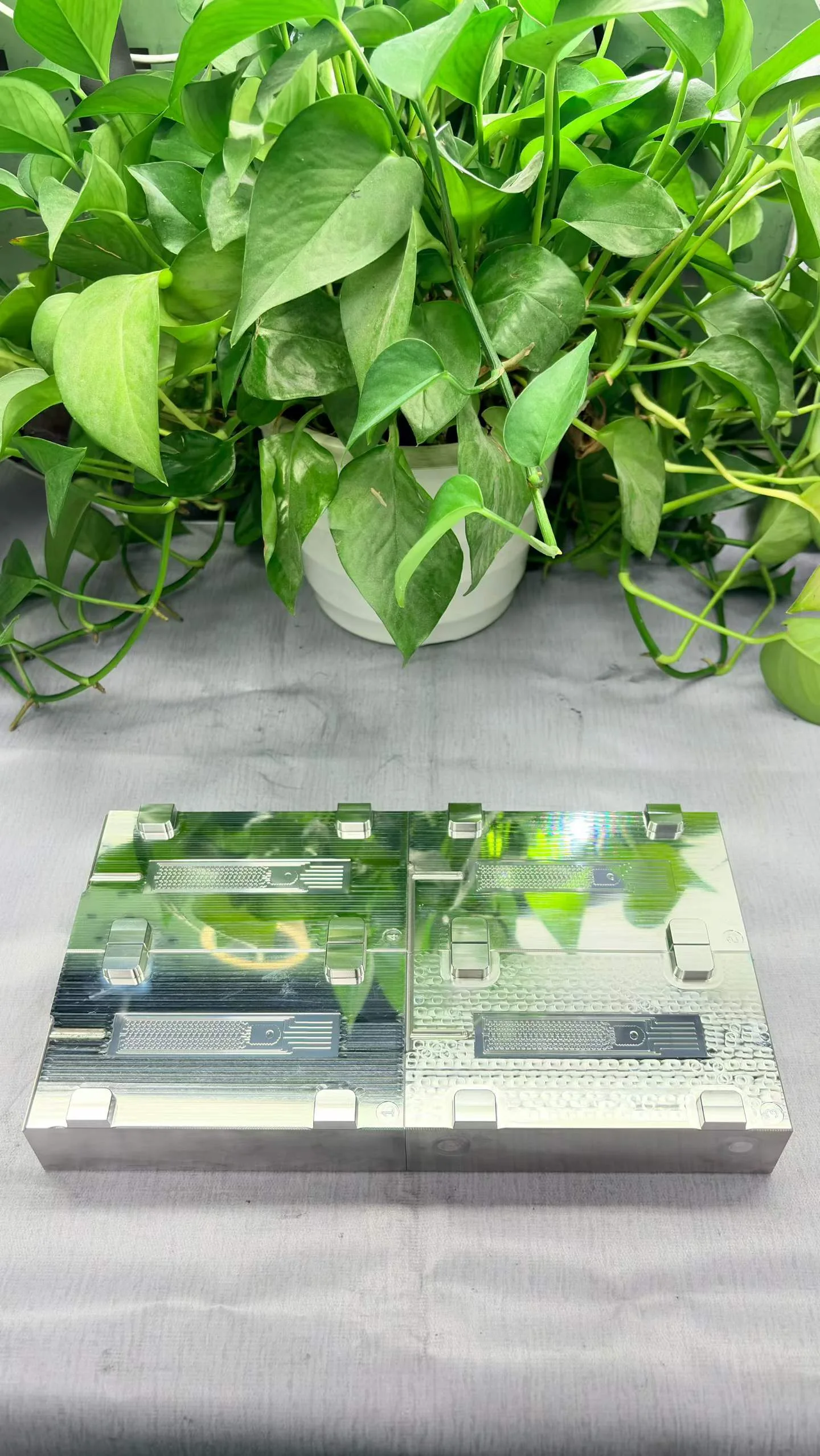
Micro features and mirror surfaces in one machining route
The difficult part was not only cutting small structures. The project also required stable geometry and a high-quality surface on the same insert.
What the machining plan needs to protect
Micro-feature machining
Review tool access, feature depth, minimum radius and the risk of local distortion before cutting.
Mirror surface machining
Improve functional surface quality without using polishing to hide geometry problems.
Complex geometry control
Keep channels, mirror zones, datums and fitting features connected to one acceptance logic.
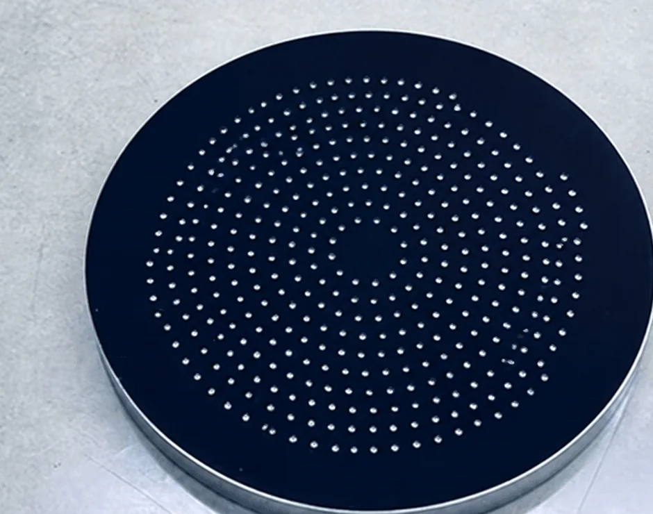
Four issues we prefer to identify before machining starts
Instead of adding more finishing steps after a problem appears, the goal is to decide the right route before the critical features are already at risk.
→Protect the micro-feature zone and avoid blanket polishing where geometry is more important than appearance.
→Review tool size, minimum radius and local finishing allowance before the machining route is fixed.
→Evaluate surface quality together with channel profile, feature position and transition geometry.
→Use a zone-based process plan so one operation does not damage the feature next to it.
What we review from your drawing
Dimensions, datums, local geometry and the actual functional structure.
The machining route changes with material condition and feature sensitivity.
Minimum widths, depths, radii and transition zones.
Which areas need mirror finish and which areas must preserve sharp geometry.
How the finished insert should be judged
A microfluidic insert should not be accepted by one roughness number alone. The important features must be reviewed together.
Questions before sending a microfluidic insert project
Short answers to the questions that normally matter before engineering review and quotation.
1. What are the main challenges in machining microfluidic mold inserts?
2. Can Yishun machine microfluidic mold inserts with mirror-finish surfaces?
3. Do you manufacture finished microfluidic chips?
4. What information do you need before quotation?
5. Does a lower Ra value always mean a better microfluidic insert?
6. Can prototype inserts be used before production tooling?
7. How do you control small channels and micro features during machining?
8. Can you support complex inserts with several functional zones?
Discuss your microfluidic mold insert before the difficult feature becomes a tooling problem
Send your drawing, material and critical feature requirements. We can first review manufacturability and identify the areas most likely to create machining risk.