
Machining Capability for AR/VR Optical Mold Inserts
Complex near-eye optical designs can combine steep aspheric slopes, freeform geometry and narrow transition zones in a very small mold insert. The key question is not whether the surface can be made shiny—it is whether the intended optical geometry can still be protected after machining, finishing and correction.
Yishun reviews the actual 2D/3D data first, identifies the high-risk surface areas, and then judges whether our five-axis, ultra-precision, finishing and inspection capabilities are suitable for the project.
Surface slope, transition zones, edge definition and datum relationships are reviewed together.
We evaluate the optical surface before choosing a machining route
AR/VR optical tooling can look simple in overall size while containing several difficult local features. A feasibility review helps prevent the wrong process from being chosen too early.
Four questions we ask first
Steep local areas and changing curvature affect tool access, contact condition and correction strategy.
Curvature transitions, small lands and narrow optical edges often carry more risk than the broad central area.
Nearby walls, recesses, insert shoulders and datum features can limit machining and finishing access.
Form, finish, edge definition and datum relationships need one consistent acceptance logic.
The machining route is built around the geometry and acceptance method
These are existing Yishun machining, finishing and inspection capabilities that can be combined when a difficult optical mold project requires them.
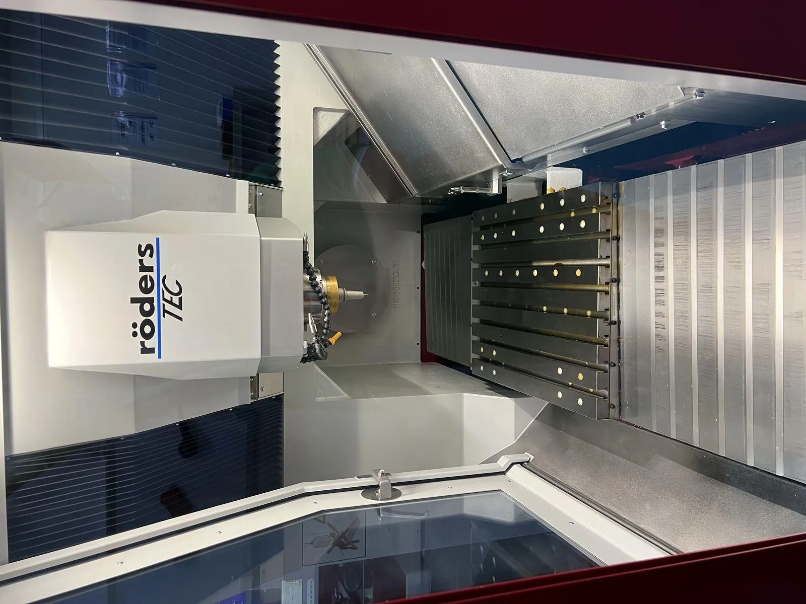
High-Precision 5-Axis Machining
Useful for freeform access, changing tool orientation and difficult surrounding structures.
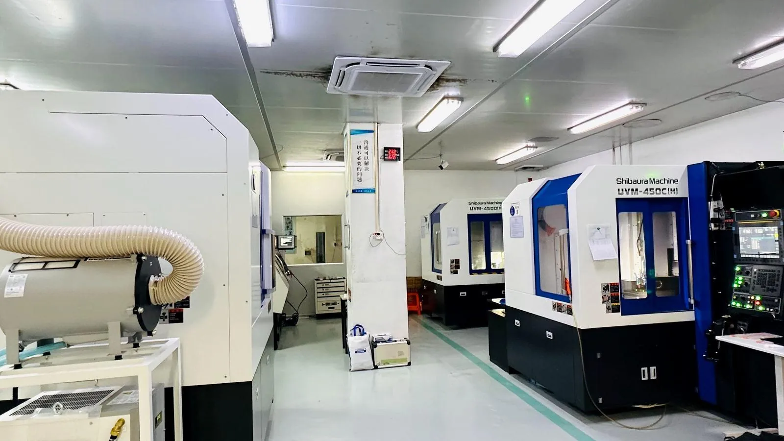
Ultra-Precision Machining
Used for suitable materials and geometries requiring high-quality optical surface generation and stable form control.
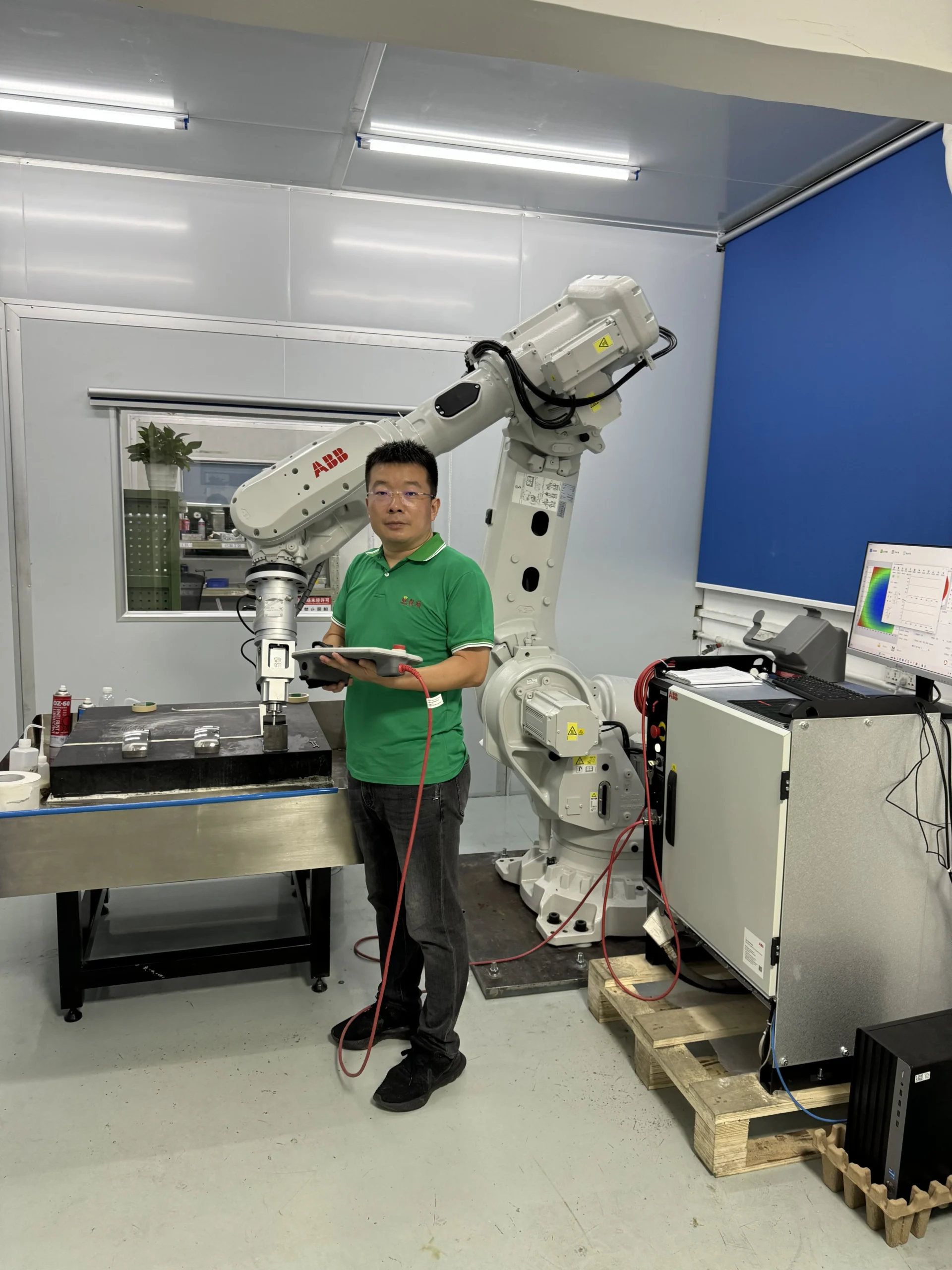
Controlled Optical Finishing
Finishing decisions are made around form protection, local transitions and edge definition—not shine alone.
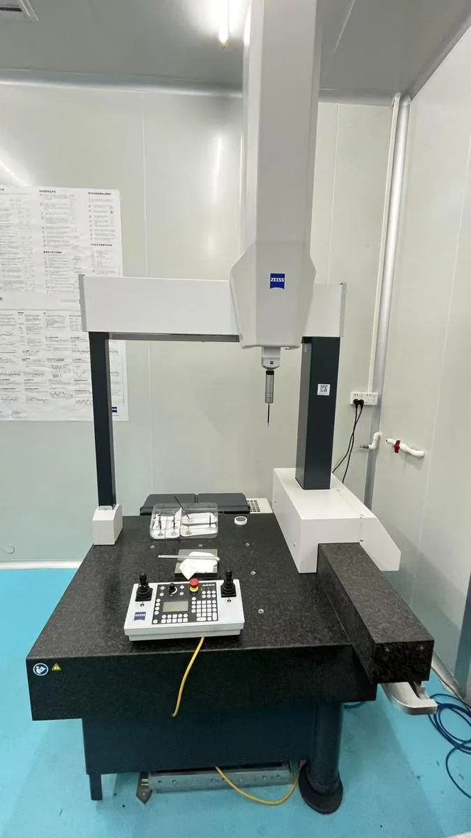
Precision Inspection
Datum, dimensional and geometry relationships are reviewed according to the actual drawing and project acceptance logic.
The hardest areas are often small, local and easy to damage during correction
The broad optical surface may machine well while a transition, edge or steep local zone becomes the real cause of rework.
Tool contact and finishing pressure can change quickly as local slope increases.
Changing curvature can expose tool-path patterns or local waviness if the route is not continuous.
Small functional boundaries can be rounded or softened by an aggressive finishing pass.
A good optical surface can still fail if its position relative to the mechanical reference is wrong.
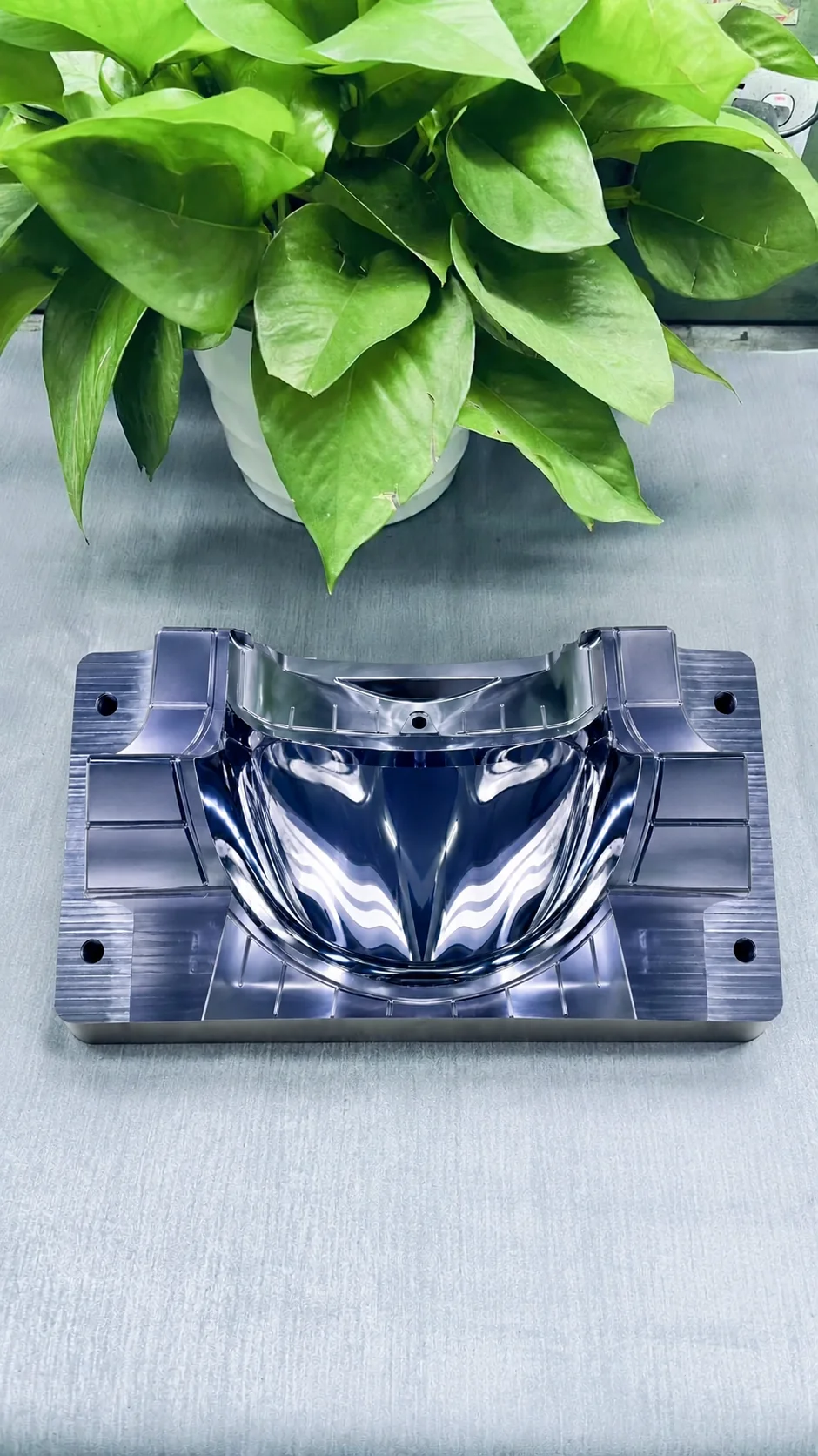
Machining, finishing and correction should follow one control logic
When each stage is treated separately, a later polishing or correction step can undo the geometry created earlier. We keep the same critical zones visible through the full manufacturing review.
Define Critical Zones
Mark the active optical surface, transitions, edges and datum relationships before process planning.
Choose the Route
Select five-axis, ultra-precision or a combined route according to geometry, material and access.
Control the Finish
Improve the required mirror surface while protecting the form already created in machining.
Judge Before Recutting
Use inspection data to understand the cause before removing more correction allowance.
Real optical insert work behind the capability
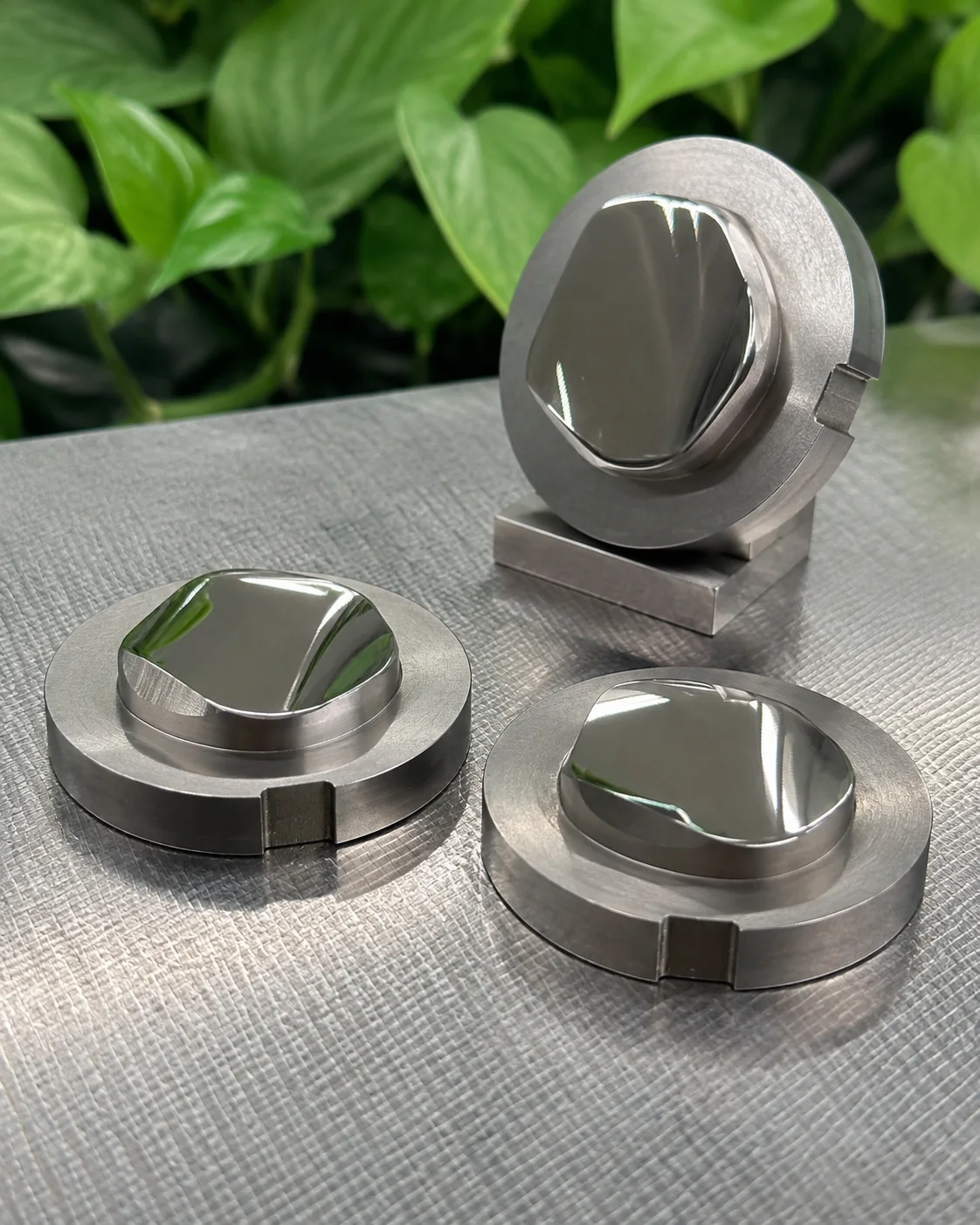
These real optical parts and mirror surfaces show the kinds of curved geometry, surface quality and local transitions that must be controlled when evaluating difficult optical tooling.
Freeform mirror insert group
Multiple mirror-finish inserts with non-circular optical surfaces and changing local curvature.
Large freeform mirror mold surface
A large polished curved surface where broad form, transition quality and reflection continuity all matter.
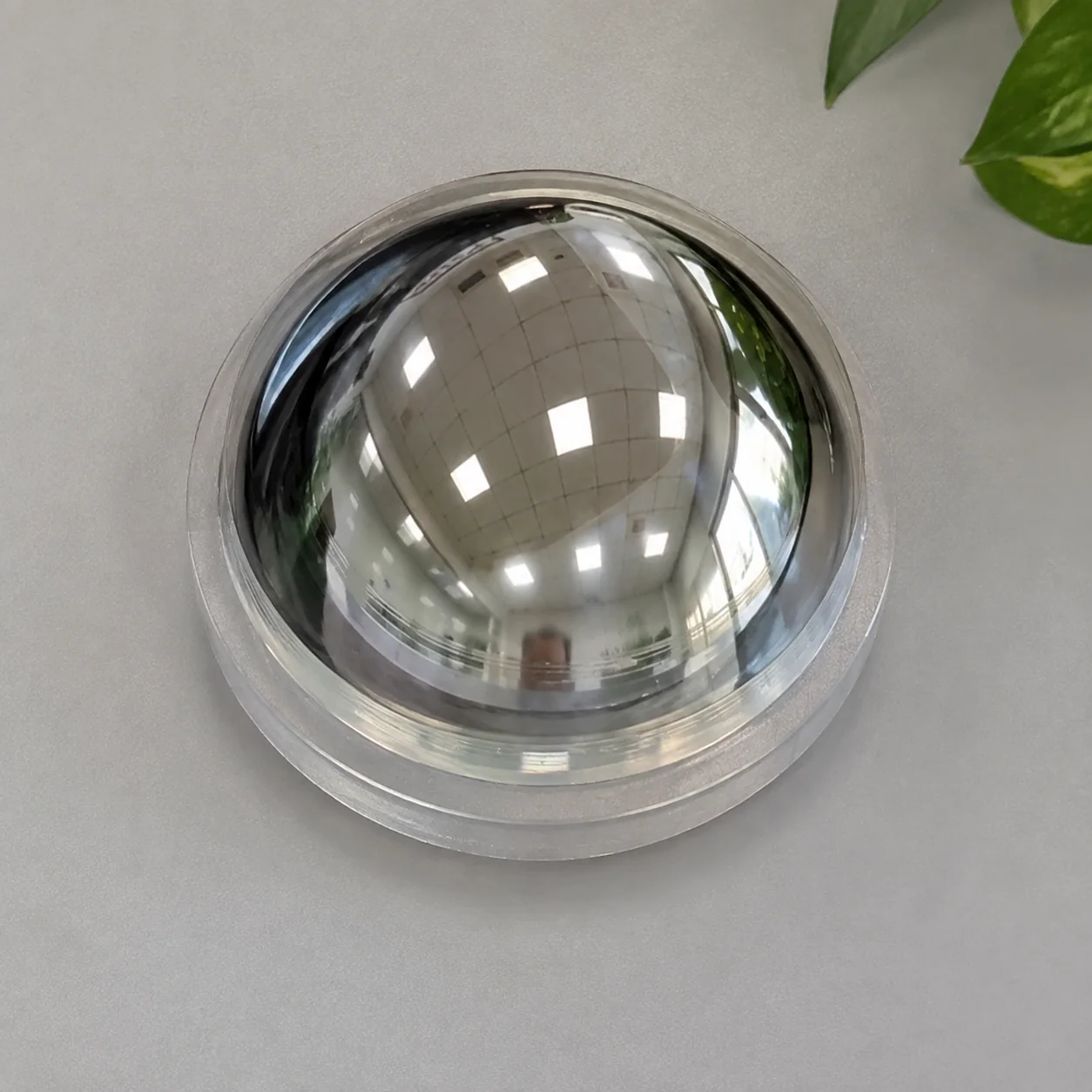
Convex optical surface sample
A highly reflective convex optical surface that highlights the importance of form stability across the full aperture.
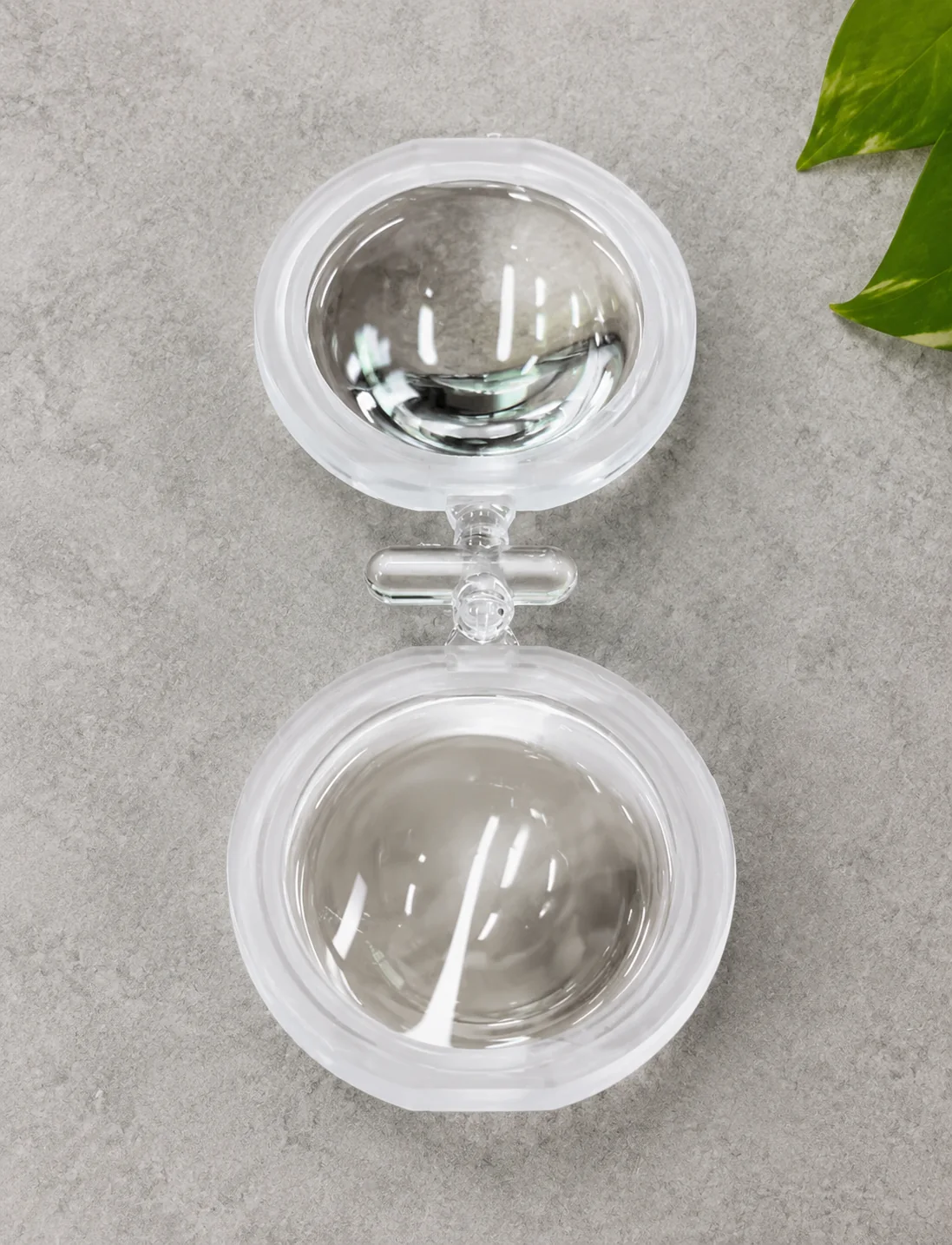
Paired optical lens samples
Paired optical samples showing the replicated curved geometry that the mold surface ultimately needs to support.
The final insert needs more than one “good” number
The acceptance method should follow the functional geometry of the insert, not just a single roughness or dimensional value.
What we need to understand from your optical mold design
Aspheric equation, freeform data or the complete 3D surface used to define the functional zone.
The material condition affects the available machining and finishing strategy.
Mark the areas where form, transition or boundary quality is most important.
Tell us which form, surface, datum or appearance requirements control the project decision.
Useful project data for a capability review
AR/VR optical mold machining capability questions
1. Can Yishun review AR/VR optical mold inserts?
2. Can you evaluate freeform optical surfaces?
3. Can you evaluate aspheric optical mold cores?
4. Why is mirror finish not enough for acceptance?
5. Can you review multi-zone or dual-curvature transitions?
6. Can you review an existing insert with polishing or tool-mark problems?
7. What inspection information should we provide?
8. What files are needed to start?
Have an AR/VR optical mold design that needs a manufacturability review?
Send the drawing and optical surface data. We can first review the difficult slopes, transition zones, surrounding structure and acceptance priorities before discussing the machining route.