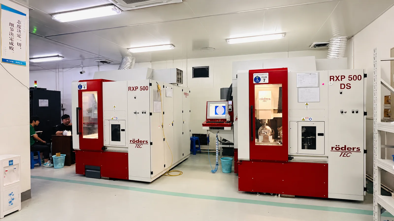
Endoscope Optical Component Mold Solution
Endoscope optics compress several demanding requirements into a very small space. For mold inserts, the challenge is not simply making a small polished surface—it is keeping optical form, edge definition, fitting references and repeatability stable together.
Yishun supports precision mold insert machining for small optical components where geometry and surface quality must be reviewed as one manufacturing problem.
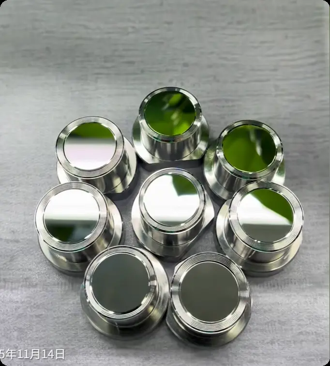
Small diameter does not mean simple tooling
When the optical component becomes smaller, the available machining margin also becomes smaller. A local radius, shoulder, transition or alignment feature can become as important as the polished surface itself.
Optical form can drift during finishing
Improving appearance is not useful if the aspheric or local optical geometry moves away from the drawing.
Small edges can lose definition
Tiny transitions, radii and shoulders need a machining route that protects the features around the optical zone.
Fitting references must stay connected
The optical surface cannot be judged separately from the datums and mounting features used later in assembly.
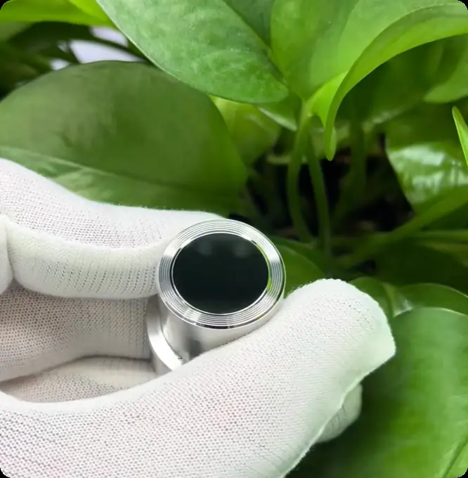
What we look at before deciding the machining route
For endoscope-related optical tooling, we first identify which features are actually optical, which features locate the component, and which local structures are most likely to be damaged by an overly aggressive finishing step.
Aspheric, spherical, freeform or other functional surface regions.
Radii, steps, narrow transitions and other size-limited structures.
The relationships that determine how the optical component is positioned later.
Three things we protect at the same time
Surface form
The optical geometry needs a stable tool path and process route before any finishing correction is considered.
Surface condition
Mirror or optical-grade areas should be improved without using polishing to hide a form problem.
Feature relationship
Optical zones, edges, datums and fitting features need to remain consistent with the drawing as a complete insert.
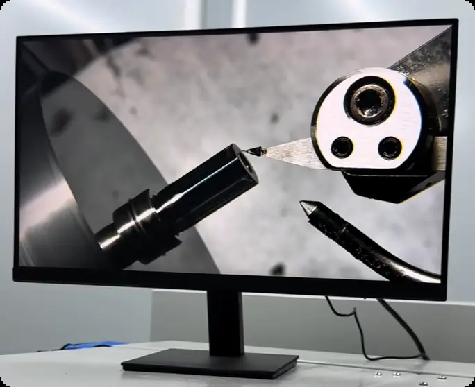
Problems that should be solved before the final surface is already finished
The goal is to avoid a cycle where every correction improves one feature but damages another.
→ Re-check the form error and machining history before adding another polishing step.
→ Separate geometry-critical zones from appearance-critical zones and control local allowance.
→ Review the datum chain and fitting features together with the optical surface.
→ Define the acceptance logic for consistency before treating one good sample as the standard.
What we need from your project
Especially the optical surface definition and the reference system.
The available machining and finishing route depends on the real material condition.
Minimum radii, optical zone, local steps and any fragile transitions.
Surface appearance, form, dimensional relationship and any matching requirements.
We would rather identify the risk before cutting
A small optical insert can become expensive when the manufacturing route is chosen only after the first surface problem appears. Drawing review helps determine the critical zones before material is removed.
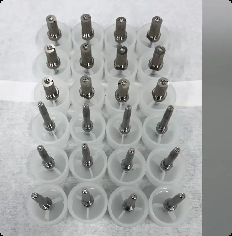
How we judge a finished endoscope optical mold insert
One roughness value is not enough. The insert should be reviewed according to the features that control optical and assembly performance.
Questions before sending an endoscope optical tooling project
Eight practical points to clarify before engineering review and quotation.
1. What type of endoscope optical mold inserts can Yishun review?
2. Do you manufacture complete endoscope devices?
3. Can mirror or optical-grade surfaces be machined on small inserts?
4. Can you support aspheric or complex optical surfaces?
5. What information is needed before quotation?
6. How do you protect small radii and edges?
7. Is low Ra enough to accept an optical insert?
8. Can you review an existing insert that already has a surface problem?
Send the optical surface and the surrounding geometry—not just the Ra target
For small endoscope optical tooling, the surrounding radii, datums and fitting features often decide whether a machining route is actually safe. Send your drawing and critical requirements for engineering review.