How Interferometers Measure Optical Surface Accuracy: A Technical Guide
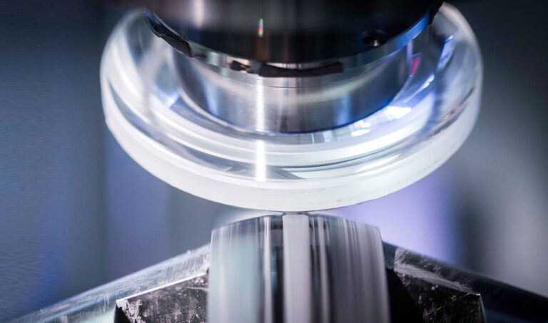
When manufacturing precision optical components, surface accuracy specifications are expressed in fractions of the wavelength of light—often λ/10, λ/20, or tighter. Achieving such tolerances would be impossible without equally precise measurement systems. Interferometry provides the fundamental measurement technology that enables optical fabricators to verify nanometer-level surface accuracy and achieve specifications that would otherwise be invisible to any other technique.
For optical engineers and quality professionals, understanding how interferometers measure surface accuracy illuminates both the capability and limitations of optical manufacturing processes. YISHUN Optical’s metrology laboratory, equipped with Zygo interferometers and environmental controls, provides traceable surface verification supporting our precision optical manufacturing operations across high-reliability optical, semiconductor, and medical device applications.
Key Takeaways
- Interferometers measure surface form by comparing test surface to a reference surface using wavelength-scale interference patterns
- Phase-shifting interferometry provides nanometer-resolution surface height maps with automated data analysis
- Common configurations include Fizeau (transmission sphere), Twyman-Green (flat testing), and Fizeau (flat testing) interferometers
- Environmental factors (vibration, air turbulence, temperature) limit achievable measurement precision
- YISHUN Optical achieves λ/20 measurement precision using stabilized Zygo systems with environmental isolation
The Physics of Optical Interference
Wavefront Interference Fundamentals
Light behaves as an electromagnetic wave with defined wavelength, amplitude, and phase. When two light waves meet, they combine additively—constructively if peaks align, destructively if peaks meet troughs. This phenomenon, called interference, provides the basis for all optical interferometry.
For monochromatic (single-wavelength) light, path length differences between interfering beams determine interference outcome:
- Path difference = 0, λ, 2λ…: Constructive interference (bright fringe)
- Path difference = λ/2, 3λ/2…: Destructive interference (dark fringe)
Since visible light wavelengths are approximately 500-600nm, interference patterns create visible fringes where surface deviations as small as 100nm (λ/5) become obvious.
Why Interference Measures Distance
Because light wavelength is precisely known (HeNe laser = 632.8nm), the interference pattern directly encodes path length differences. One complete bright-to-bright fringe transition represents exactly one wavelength of path difference—approximately 633nm on a round-trip reflection.
This wavelength-encoded measurement enables surface deviations of nanometers to be detected through fringe patterns visible to trained observers.
Interferometer Configurations for Optics
Fizeau Interferometer
The Fizeau interferometer is the most common configuration for measuring spherical and planar optical surfaces:
Configuration:
- Collimated laser light illuminates the test surface
- Reference flat (or transmission sphere) positioned close to test surface
- Light reflects from both surfaces; interference occurs between reflections
- Interference pattern captured by camera and analyzed
Advantages:
- Reference surface placed very close, minimizing environmental disturbances
- Transmission spheres enable null testing of spherical surfaces
- High measurement accuracy (λ/20 typical)
- Standard configuration for ISO 10110-7 surface quality verification
Twyman-Green Interferometer
The Twyman-Green configuration tests optics in transmission:
Configuration:
- Beam splitter divides collimated laser beam
- Test optic placed in one arm; reference mirror in other
- Recombined beams create interference pattern
Applications:
- Lens testing with null corrector optics
- Interferometer system verification
- Testing optics in simulated use configuration
Point Diffraction Interferometer
Point diffraction interferometers generate reference waves from a pinhole diffraction source:
Advantages:
- Reference wavefront quality limited only by pinhole optics
- Achieves λ/1000+ measurement capability
- Suitable for extremely low-aberration optics
Limitations:
- Lower light efficiency; longer acquisition times
- Specialized equipment for highest-precision applications
Phase-Shifting Interferometry
How Phase-Shifting Works
Traditional interferometry interprets fringe patterns visually—effective but limited by human interpretation and environmental stability requirements. Phase-shifting interferometry (PSI) dramatically improves precision by:
- Capturing multiple interferograms with controlled phase shifts between reference and test beams
- Using piezoelectric transducers (PZTs) or other phase modulators to introduce known phase delays
- Processing the intensity data mathematically to extract surface height at each pixel
PSI algorithms calculate surface height from intensity variations:
Height(x,y) = [φ(x,y) × λ] / (4π)
Where φ represents the measured phase at each point.
PSI Advantages
- Nanometer resolution: Surface heights calculated with < 1nm precision
- Full-aperture mapping: Complete surface captured, not just profiles
- Automated analysis: Operator subjectivity eliminated
- Statistical processing: Noise reduced through averaging multiple frames
- Digital存档: Data stored for process control and documentation
Interpreting Interferograms
Fringe Patterns and Surface Deviations
An interferogram displays concentric or straight fringes representing contours of equal surface height difference relative to the reference surface. Each fringe represents λ/2 (316nm) of path difference.
Reading an Interferogram:
- Parallel straight fringes: Flat surface; deviation indicated by fringe spacing and straightness
- Circular fringes: Spherical surface; fringe spacing indicates radius
- Tilted fringes: Surface tilt relative to reference
- Irregular fringes: Surface figure errors requiring correction
Quantitative Analysis
Modern interferometer software converts fringe patterns into precise numerical data:
| Parameter | Description | Typical Specification |
|---|---|---|
| PV (Peak-to-Valley) | Maximum height difference across aperture | λ/10 = 63nm |
| RMS | Root mean square surface deviation | λ/50 = 13nm |
| Power | Curvature error (parabolic component) | Specific to application |
| Irregularity | Surface deviation after power removal | λ/4 to λ/20 |
Environmental Factors Affecting Measurement
Vibration Isolation
Even microscopic vibrations cause fringe motion that degrades measurement precision:
- Sensitive to 10-100Hz vibration from building systems, HVAC, foot traffic
- Active vibration isolation tables required for λ/20+ measurements
- Measurement timing optimized for low-activity periods
- Air isolation tables insufficient for highest precision requirements
Air Turbulence
Temperature variations in the air create refractive index fluctuations that distort wavefronts:
- Path lengths > 100mm particularly sensitive
- Environmental enclosures minimize turbulent air movement
- Measurement duration minimized to reduce cumulative turbulence effects
- Filtered, temperature-stabilized air for critical measurements
Temperature Stability
Thermal expansion affects both test optics and reference surfaces:
- 1°C temperature change causes ~10μm/m expansion in glass
- ±0.1°C stability required for λ/20 measurements
- Thermal equilibrium achieved before measurement begins
- Temperature gradient across optics creates measurement artifacts
Measurement Uncertainty and Calibration
Reference Surface Calibration
Interferometer reference surfaces require periodic calibration:
- Traceable to national standards (NIST, NPL, etc.)
- Calibration uncertainty included in measurement budget
- Aging effects on reference flats require periodic re-certification
- Cleaning procedures critical to maintain calibration integrity
Uncertainty Budget
YISHUN Optical’s metrology uncertainty budget accounts for:
- Instrument repeatability: Statistical variation in repeated measurements
- Reference surface uncertainty: Calibration traceability chain
- Environmental effects: Vibration, turbulence, temperature contributions
- Alignment errors: Tilt, decentration, focus setting effects
- Wavelength accuracy: Laser wavelength verification
Practical Applications in Optical Manufacturing
Surface Figure Verification
Every surface YISHUN Optical manufactures is verified using interferometry:
- Final inspection confirms specifications are met
- In-process measurements during multi-stage polishing
- Before and after advanced finishing (MRF, IBF)
- Shipping certification with measurement data
Radius of Curvature Measurement
Interferometers measure spherical surface radii with high precision:
- Spherical mirrors and lenses: Radius verification to ±0.01%
- Transmission sphere calibration: Ensures null test conditions
- Radius drift monitoring: Detects tool wear or process drift
Wavefront Testing
Interferometric wavefront testing verifies complete optical systems:
- Lens assemblies: MTF-correlated wavefront measurements
- Telescope systems: End-to-end performance verification
- Laser cavity alignment: Mode quality confirmation
YISHUN Optical’s Metrology Capabilities
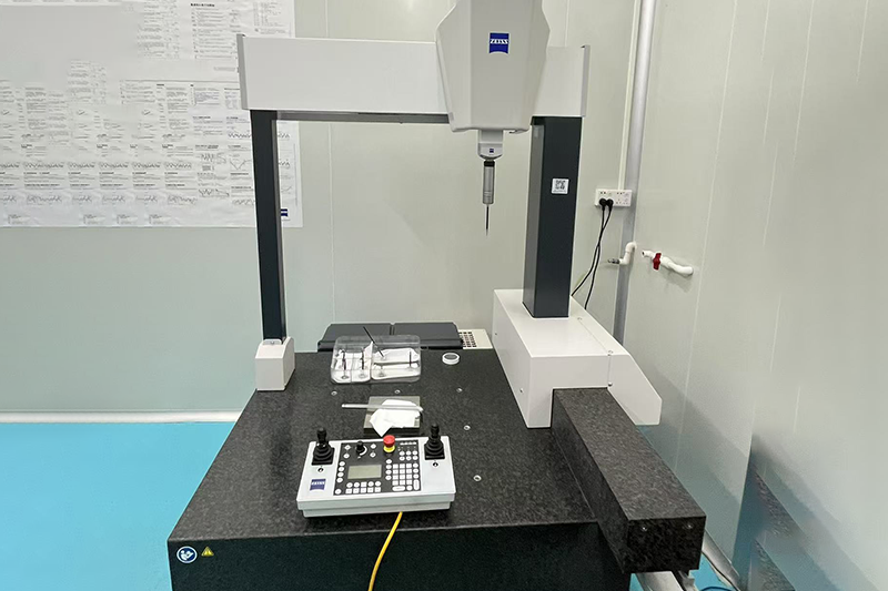
YISHUN Optical’s metrology laboratory features:
- Zygo VeriFire interferometers with Phase-Shifting PSI capability
- Transmission spheres covering 0.5X to 4X magnifications
- Vibration-isolated measurement stations on concrete piers
- Environmental enclosures with temperature stabilization
- ISO 9001:2015 traceable calibration system
- Full-aperture and sub-aperture stitching for large optics
Our measurement uncertainty of λ/20 (31nm) PV provides confidence that your optical components meet specified tolerances.
Frequently Asked Questions
What does λ/10 surface accuracy mean?
λ/10 PV (Peak-to-Valley) surface accuracy means the maximum height difference across the optical surface is no more than one-tenth of the measurement wavelength (typically 632.8nm HeNe). This equals approximately 63nm—about 1/10,000th the thickness of a human hair.
Why are interferometers better than CMM for optics?
CMM (Coordinate Measuring Machines) measure discrete points with touch-probe styli, potentially damaging delicate surfaces. Interferometers measure continuously across the entire aperture without contact, achieving 100-1000X better resolution for surface form measurement.
Can interferometers measure surface roughness?
Standard interferometers measure surface form (low-spatial-frequency errors) but are not optimized for high-spatial-frequency roughness. Surface roughness requires profilometers (TalySurf) or interferometric microscopy (phase-shift interference microscopes).
What causes irregular fringe patterns?
Irregular fringes indicate surface figure errors—deviations from the intended spherical, planar, or aspheric shape. These may arise from machining errors, polishing irregularities, tooling problems, or material inhomogeneities requiring additional processing to correct.
How long does an interferometric measurement take?
Modern phase-shifting interferometry captures complete surface maps in seconds. Including setup, alignment, and data analysis, a typical measurement cycle is 5-15 minutes per part. Higher precision measurements may require longer acquisition times to average environmental effects.
Conclusion
Interferometry provides the measurement foundation that makes precision optical manufacturing possible. By comparing test surfaces to precisely calibrated reference surfaces at wavelength-scale precision, interferometers enable surface accuracy verification of nanometers—unachievable by any other practical means.
Understanding interferometer principles, configurations, and limitations helps engineers and procurement professionals appreciate both the capability and requirements of precision optical manufacturing. YISHUN Optical’s investment in Zygo interferometers, environmental controls, and trained metrology staff ensures accurate verification of the most demanding optical specifications.
Need precise surface metrology for your optical components? Contact YISHUN Optical at info@yishunoptical.com or visit yishunoptical.com to discuss your measurement requirements.