When I first read the message from this UK medical optics customer, one number immediately stood out:
0.002 mm.
The parts themselves were small — no more than around 30 mm in length and 20 mm in diameter — but the requirements were anything but simple.
Some critical dimensions required tolerances as tight as 0.002 mm.
For the optical surfaces, the customer required approximately Ra 10 nm directly from machining, without polishing.
The optical components were mainly specified in Aluminium 7075, while inserts without the lathed optical surfaces were typically produced from Stavax or similar mold steels.
And there was another requirement that mattered just as much as the machining:
the parts had to be supported by dimensional inspection reports.
I knew immediately that this was not the kind of project where a quick “yes, we can make it” would help anyone.
The real question was whether the machining process and the measurement process could support the same level of accuracy.
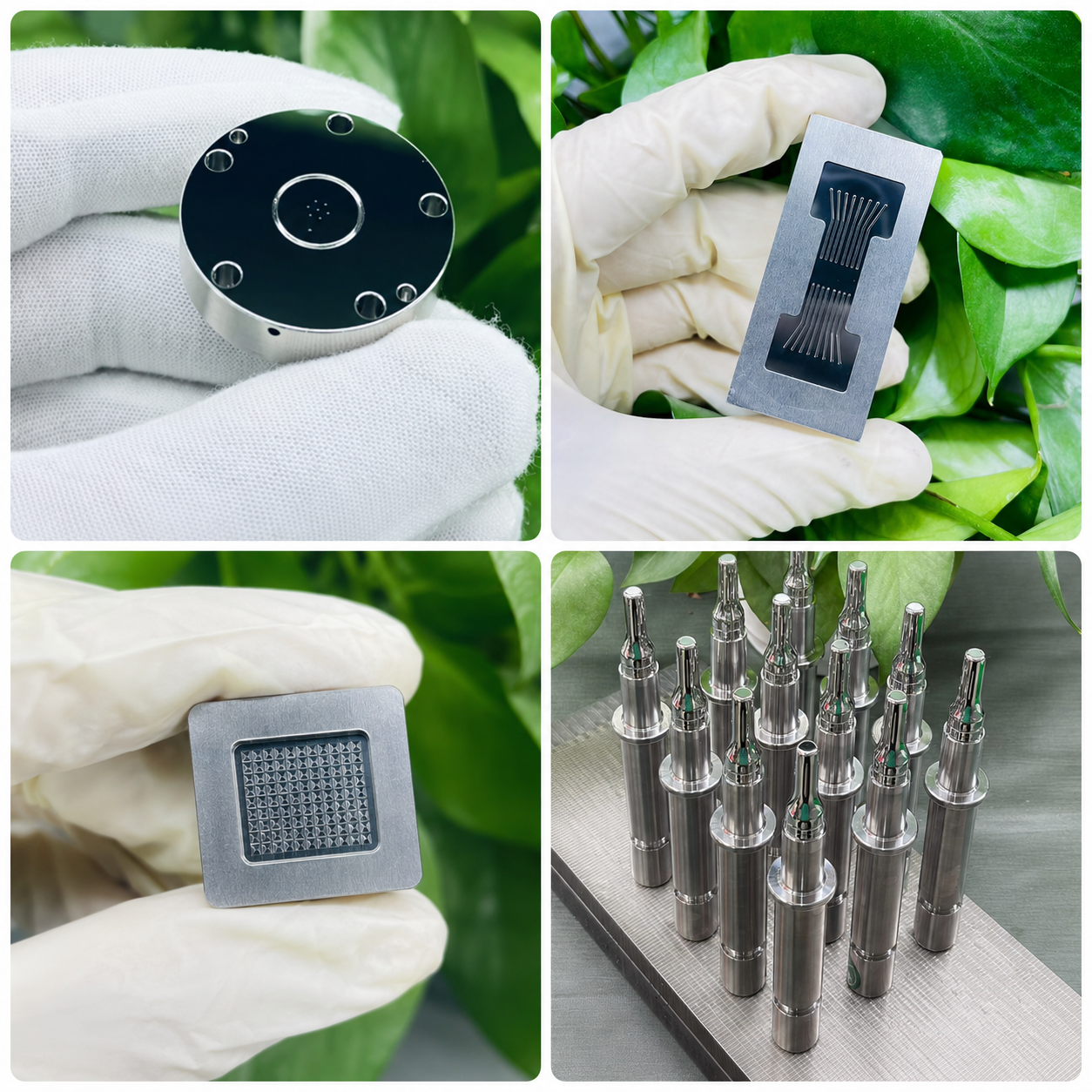
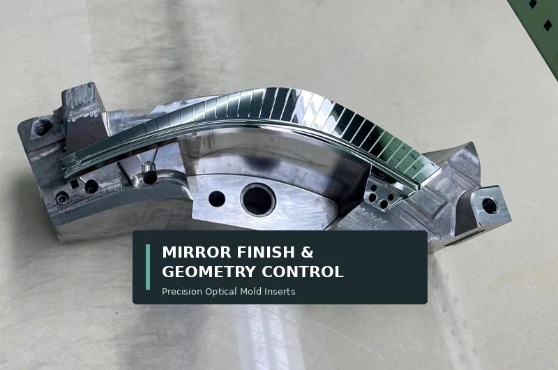
The product images shown in this case study represent comparable YISHUN precision machining work. Customer-specific geometry is protected under NDA.
Project Requirements at a Glance
| Requirement | Customer Requirement |
|---|---|
| Component Type | High-accuracy inserts with and without optical surfaces |
| Maximum Size | Approx. 30 mm length × 20 mm diameter |
| Critical Tolerance | Up to 0.002 mm |
| Optical Surface Roughness | Approx. Ra 10 nm |
| Surface Condition | Direct machining, without polishing |
| Optical Component Material | Aluminium 7075 |
| Other Component Material | Stavax or similar |
| Inspection Requirement | Dimensional reports required |
| Surface Metrology | White light interferometer measurement available |
The Customer Was Verifying Capability Before Asking for a Quote
The first conversation was not about price.
The customer was already sourcing these components from suppliers in both China and Europe.
Before sending a drawing, they wanted to understand whether YISHUN genuinely had the machining and metrology capability required for this type of high-accuracy medical optical insert.
They also explained why they were evaluating another supplier.
Their existing Chinese supplier had experienced difficulties maintaining the required tolerances consistently.
That sentence told us more about the project than any general purchasing request could have.
The issue was not whether somebody could machine the basic shape.
The issue was whether the supplier could keep several things under control at the same time:
- critical dimensions;
- optical surface quality;
- datum relationships;
- machining stability;
- and inspection results.
At 0.002 mm, these are no longer separate questions.
They become one manufacturing system.
We Evaluated the Requirements Before Confirming Capability
For high-accuracy components like these, we do not confirm capability simply because one machine specification looks better than the tolerance on the drawing.
Our engineering team considered the material, part size, tolerance level, optical surface requirement, machining route and inspection expectations together.
We also looked at one particularly important detail:
Ra 10 nm had to come directly from machining.
There would be no later polishing step available to correct or improve the optical surface.
After the technical review, we confirmed that the requirements were within our processing scope.
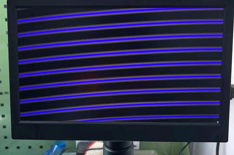
We also confirmed that the required inspection support could be provided, including white light interferometer measurement for relevant optical surface characteristics and dimensional inspection according to the drawing.
For a project involving nanometer-level surface requirements and micron-level dimensional control, a part cannot simply look good.
The result has to be measurable.
The Capability Review Quickly Became a Real Project
After receiving our technical response, the customer told us that our capabilities appeared to fit the project requirements well.
Shortly afterwards, an actual component drawing arrived for evaluation and quotation.
That was the moment the conversation changed.
It was no longer a general capability discussion.
Now we could review the actual:
- geometry;
- tolerance distribution;
- material;
- critical features;
- optical surface requirements;
- and inspection expectations.
Our team completed the technical review and provided the quotation on the same day.
I have always believed that speed matters in international technical communication — but not in the same way that speed matters in machining.
If a requirement is clear enough to evaluate, there is little value in making the customer wait several days for basic technical feedback.
Fast communication reduces uncertainty.
The manufacturing process, however, has to follow a different rule.
When the Customer Asked for a Shorter Lead Time
After reviewing our quotation, the customer asked whether the delivery schedule could be brought forward.
This was probably the most important moment in the discussion.
Of course, we wanted to make the schedule as attractive as possible.
But we also had to go back to the reason the customer contacted us in the first place:
tolerance consistency.
For components with critical tolerances reaching 0.002 mm, a shorter lead time only has value if machining stability, inspection and quality control are not compromised.
So instead of simply reducing the number on the quotation, we explained why the process needed enough time for:
- material and blank preparation;
- datum establishment;
- machining sequence control;
- critical dimension verification;
- optical surface machining;
- intermediate inspection;
- final dimensional measurement;
- surface measurement where required;
- and final quality review.
As both sides become more familiar with the component requirements, documentation and inspection expectations, overall efficiency can naturally improve.
But for this project, establishing a stable process came first.
The customer understood the reasoning, accepted the proposed schedule and decided to move forward.
That was reassuring.
Not because we had persuaded the customer to accept a longer lead time, but because both sides were making the decision around the same priority:
getting the part right.
Why 0.002 mm Is More Than a Machine Specification
A 0.002 mm tolerance is only two microns.
At this level, simply owning a high-precision machine does not guarantee a compliant part.
Small variables begin to consume a meaningful portion of the tolerance:
- temperature variation;
- workholding and clamping force;
- datum consistency;
- machining sequence;
- tool condition;
- material response;
- inspection timing;
- and the relationship between machining and measurement.
Small parts can actually make some of these issues more sensitive.
With a component around 30 mm × 20 mm, critical features may sit close together, the available clamping area may be limited, and very small dimensional changes can consume a large percentage of the tolerance window.
That is why we do not treat machine positioning accuracy as the same thing as finished-part accuracy.
The final question is always:
Can the actual component be manufactured, measured and documented against the drawing?
That is the standard that matters.
Ra 10 nm Directly From Machining — Without Polishing
The optical surface requirement made this project especially interesting.
The customer required approximately Ra 10 nm, with no polishing afterwards.
That changes the manufacturing logic completely.
When polishing follows machining, the machined surface is only one stage in the final surface-generation process.
Here, the required optical surface had to come directly from machining.
That places much greater emphasis on:
- tool geometry and tool condition;
- cutting parameters;
- spindle stability;
- machine thermal behaviour;
- Aluminium 7075 material response;
- vibration control;
- surface generation strategy;
- environmental stability;
- and the relationship between form accuracy and surface roughness.
For this type of Aluminium 7075 optical component, the process is much closer to ultra-precision optical machining than conventional CNC machining.
A reflective appearance alone means very little.
The surface has to be generated in a controlled, repeatable and measurable way.
Ultra-Precision Machining Capability Behind This Requirement
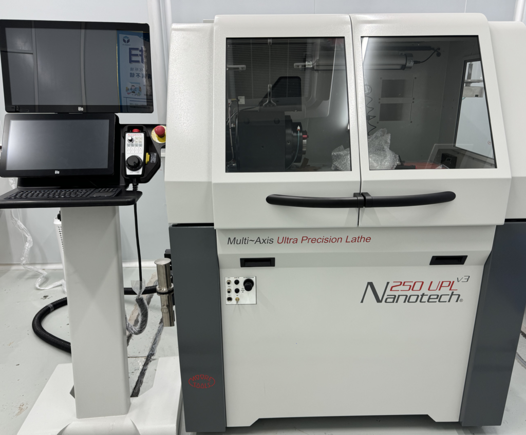
For suitable diamond-turned optical surfaces, YISHUN uses a Moore Nanotechnology 250UPL ultra-precision single-point diamond turning system.
Our documented equipment reference lists form accuracy capability of ≤0.1 μm and surface roughness capability down to ≤2.0 nm under suitable machining conditions.
Those figures are equipment capability references, not automatic guarantees for every geometry or material.
Actual achievable results still depend on the component, material, optical surface definition and agreed inspection method.
That distinction matters.
A machine tells us what process window may be available.
The drawing tells us whether that process can actually be applied to the part.
Representative YISHUN precision insert machining
Inspection Is Part of the Manufacturing Plan
One of the customer’s first questions was whether we had the required metrology.
That made sense.
If a supplier is being evaluated because of a tolerance-consistency problem, machining capability without measurement capability does not solve the problem.
For us, inspection planning begins before the machining process is complete.
We need to establish:
- which dimensions are critical;
- which datums will control the inspection;
- which features require intermediate verification;
- which measurement method is appropriate;
- whether optical surface morphology needs to be measured;
- and how the final data will correspond to the drawing.
Different requirements need different measurement methods.
Optical Surface Measurement
For relevant optical surfaces, YISHUN can use ZYGO white light interferometry to evaluate characteristics such as surface roughness and three-dimensional surface topography.
This is particularly relevant where the customer needs evidence that the optical surface was generated within the intended surface-quality range.
Dimensional Verification
Dimensional, datum and geometric relationships are evaluated using the appropriate precision metrology according to the component geometry and drawing requirements.
YISHUN’s inspection capability includes ZEISS coordinate measurement equipment for suitable dimensional and geometric verification.
The objective is not simply to produce another PDF report.
The objective is to make sure the machining process and the inspection process are evaluating the same requirements.

What Made the Customer Move Forward
Looking back at the project, I do not think the decision came down to one machine or one impressive specification.
It came from the process.
The customer had a real problem with tolerance consistency.
They first asked whether we could support the machining and measurement requirements.
We reviewed the technical conditions before confirming capability.
They then sent us an actual drawing.
We responded quickly with the technical evaluation and quotation.
When the delivery question came up, we explained why process stability mattered more than an aggressive promise.
The customer understood our reasoning and chose to proceed.
For me, that is what a strong precision-manufacturing relationship should look like.
Not:
“Can you make this?”
followed by:
“Yes.”
But rather:
Where is the risk?
How will it be controlled?
How will we measure the result?
When both sides can discuss those questions clearly before production, many problems become much easier to prevent.
Related Medical Precision Machining Experience
Medical precision projects do not all look the same.
Some involve optical surfaces.
Others involve microchannels, fine features, difficult datum relationships or extremely limited tolerance windows.
One separate example from YISHUN’s medical precision work is a medical microfluidic mirror-finished mold with dense multi-channel structures.
It is a very different geometry from the confidential UK component discussed in this case, but the manufacturing principle is similar:
small features, dimensional relationships and surface requirements have to be controlled together rather than one at a time.
That is the type of work our engineering team is accustomed to reviewing.
What Types of Medical Optical Insert Projects Can We Review?
This project is one example of the type of high-accuracy work YISHUN Optical can evaluate.
Typical requirements may include:
- medical optical precision inserts;
- custom optical mold inserts;
- small high-accuracy precision components;
- Aluminium 7075 optical components;
- Stavax precision inserts;
- directly machined optical surfaces;
- aspheric or freeform optical surfaces;
- and projects where an existing supplier is struggling with dimensional consistency.
The most useful starting point is usually not a capability table.
It is the drawing.
Frequently Asked Questions
Can you machine medical optical inserts with 0.002 mm tolerances?
Projects with critical tolerances around 0.002 mm can be evaluated, but achievable results depend on the actual geometry, datum structure, material, feature accessibility and inspection method.
We confirm capability after reviewing the drawing rather than treating one tolerance value as a universal machining specification.
Can an optical surface reach Ra 10 nm without polishing?
For suitable materials, geometry and machining conditions, this type of requirement can be evaluated through ultra-precision machining.
The final result depends on the machining route, cutting tool condition, material response, form requirement and agreed measurement method.
Can YISHUN machine Aluminium 7075 optical inserts?
Yes. Aluminium 7075 components can be evaluated for ultra-precision optical machining.
The recommended process depends on geometry, required surface quality, form accuracy and dimensional requirements.
Can you machine Stavax precision inserts?
Yes.
Stavax and similar mold steels can be evaluated for high-accuracy insert machining according to hardness, geometry, tolerance and required surface condition.
Do you provide dimensional inspection reports?
Yes.
Inspection reports can be provided according to the confirmed drawing, critical dimensions and agreed inspection scope.
Can you provide white light interferometer measurement data?
Yes, where the measurement method is suitable for the required optical surface.
White light interferometry can support evaluation of characteristics such as surface roughness and three-dimensional surface topography.
Send Your Medical Optical Insert Drawing for Technical Review
If your current supplier is struggling with tolerance consistency, or your project combines tight dimensional tolerances with demanding optical surface requirements, send us the drawing before deciding whether the job is “possible” or “impossible.”
Useful information includes:
- 2D drawing;
- 3D model;
- material;
- critical tolerances;
- optical surface definition;
- roughness requirement;
- inspection requirement;
- required report format;
- quantity;
- and target delivery schedule.
Our engineering team can review the machining difficulty, measurement strategy and potential process risks before production begins.
Send Drawings for Technical Review
Yishun Optical
Ultra-Precision Mirror Machining & Custom Mold Insert Solutions