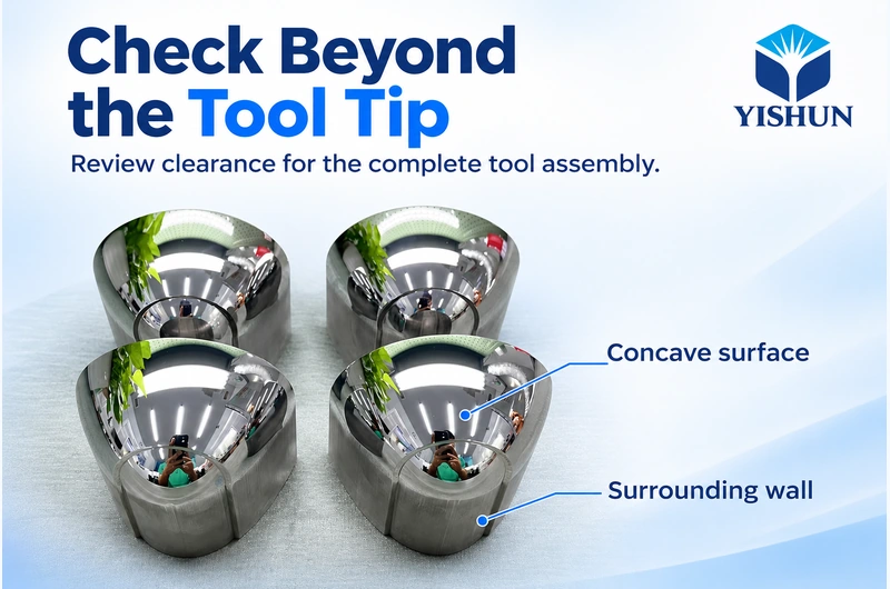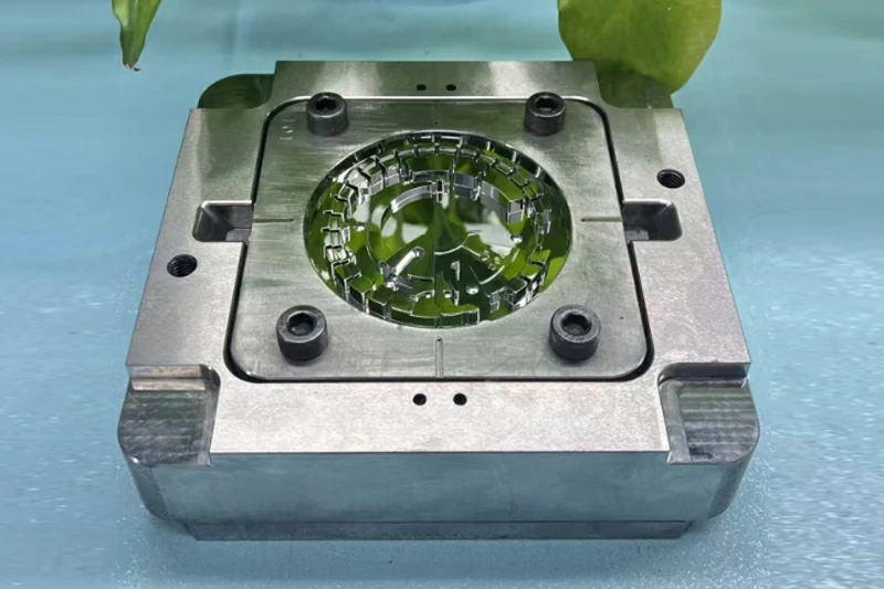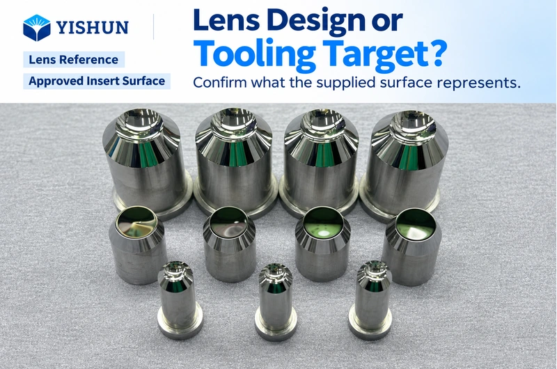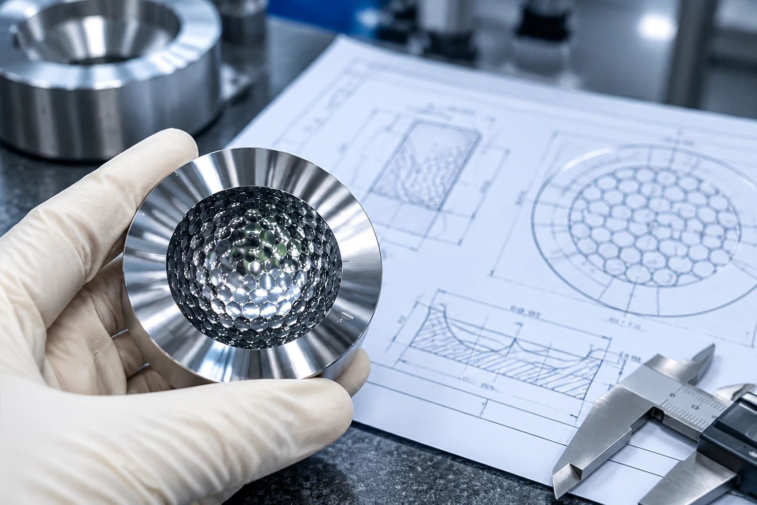
The insert slides into a round pocket and seats against its support face. Its diameter and height appear correct. During assembly, however, the toolmaker asks which direction the working surface should face.
The cylindrical body provides no obvious answer.
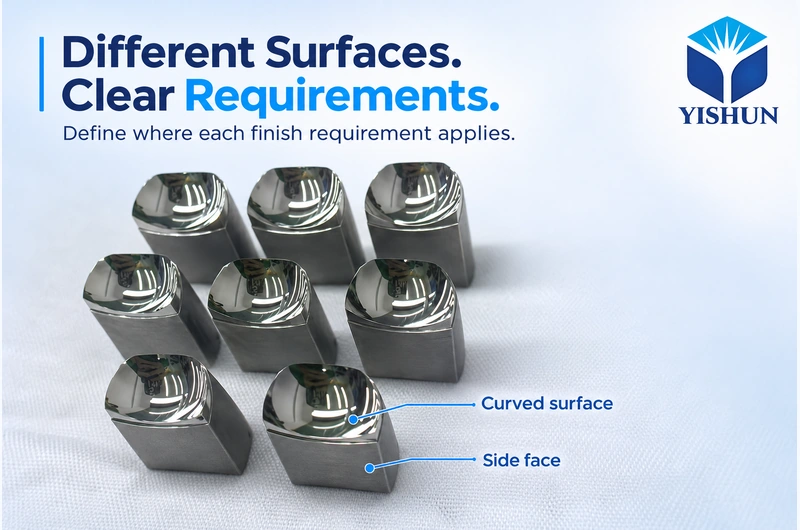
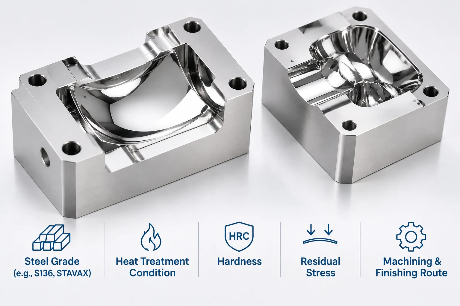
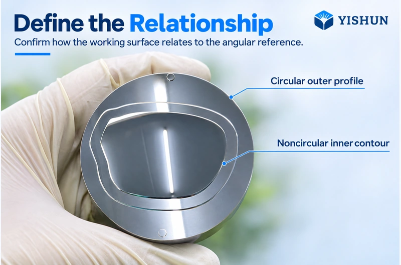
For a mold insert with a non-rotationally symmetric working surface, rotation around the body axis may change how that surface relates to the rest of the mold. The outside can be round while the functional geometry remains directional.
That angular relationship—often called clocking—needs to be defined before the team relies on the part’s appearance to establish orientation.

Roundness Does Not Define Angular Position
A cylindrical locating diameter can help establish a center position. A support face can establish an axial position. Neither necessarily provides a unique direction around the axis.
If the working surface has different profiles in different directions, more than one rotational position may fit mechanically while only one satisfies the intended arrangement.
This is not an issue for every round insert. The requirement depends on the actual surface and assembly. A rotationally symmetric surface may not need the same angular control, although surrounding features can still introduce a directional requirement.
The first question is whether rotation changes a relationship that matters to the design.
Define the Relationship, Not Just an Arrow
An arrow marked “up” can be useful, but only when everyone understands what it references.
Does it indicate the top of the drawing, the installed mold position or a direction in the optical design? Is the part being viewed from the working surface or from the back?
Define the required relationship using the approved drawing and assembly references. Identify the feature that establishes angular position and the direction to which the working surface must relate.
If an angular tolerance is necessary, the design owner should specify it according to the functional requirement. The machining supplier should not invent a limit simply because a particular value is convenient to inspect.
State the Viewing Direction
A direction that appears clockwise from one end appears counterclockwise from the opposite end.
This creates a communication risk when one person reviews the working face while another handles the insert from the rear.
Use an identified view or an explicit viewing direction when describing angular position. A photograph may support the instruction, but it should not leave the observer to infer which face is toward the camera.
Also distinguish orientation from handedness. Turning an insert around its axis does not necessarily produce the opposite-handed geometry required for another position. Confirm the intended configuration rather than treating a mirrored design as a rotated copy.
Separate Identification From Physical Location
A mark can help someone recognize the intended direction. It does not physically prevent the insert from rotating.
Conversely, a locating feature may establish direction without providing a readable indication during handling.
Decide whether the project needs a visual aid, a mechanical locating feature or both. Possible arrangements may involve an approved flat, key, pin relationship or another customer-defined feature.
These options are not interchangeable. Their suitability depends on available space, component strength, mating geometry and assembly requirements.
Any added feature must be approved. Do not machine an extra flat or hole merely to create a convenient workshop reference.
Establish Direction Through the Manufacturing Sequence
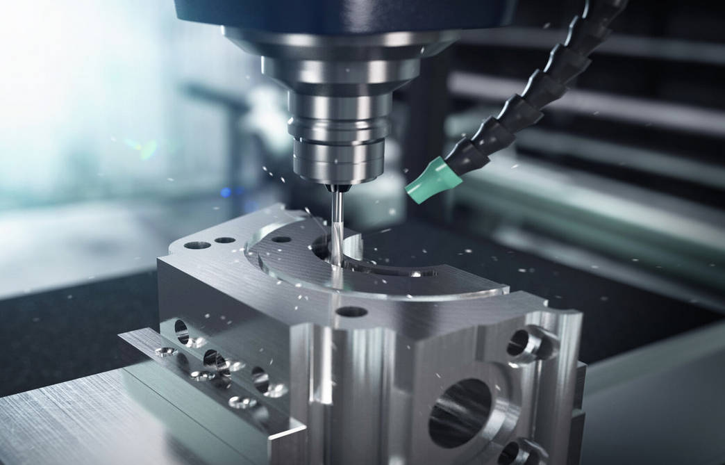
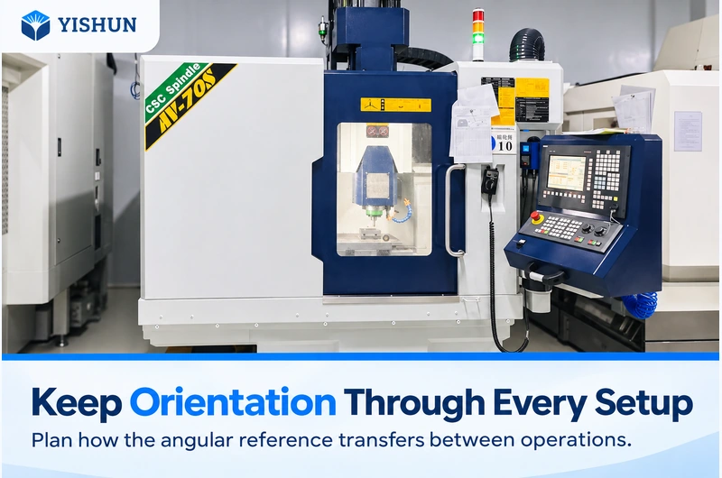
When the working surface and angular reference are produced in different operations, their relationship must survive the setup changes.
The process plan should identify how direction is established initially, how it is transferred and which feature remains available after later machining or finishing.
For freeform optical mold cores, this relationship can matter independently of how smooth the working surface looks. A correct local shape still needs to occupy the intended position relative to the insert’s locating features.
Review whether a planned operation could remove, obscure or alter the reference used earlier. If the reference changes, define how the required relationship will be recovered and checked before work continues.
Distinguish Surface Matching From Assembly Orientation
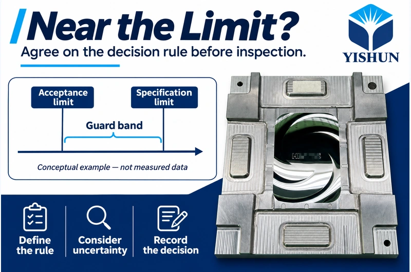
Inspection may establish the shape of a surface, its position relative to mechanical features, or both.
Those are different questions.
Clarify how the evaluation treats rotation around the insert axis. An alignment that allows the measured surface to rotate for comparison should not be assumed to prove its required angular relationship to the assembly reference.
Where clocking is part of acceptance, agree on how the physical angular reference enters the evaluation. Keep the surface result and the orientation result distinguishable so reviewers know what each establishes.
The appropriate verification method depends on the geometry and requirement. It should be agreed for the project rather than inferred from the availability of a particular instrument.
Make Removal and Reinstallation Repeatable
Orientation control must remain usable after the first assembly.
During maintenance, the original person who installed the insert may not be present. A temporary pen mark may have disappeared, and the component may have been cleaned or refinished.
The maintenance team needs a reliable way to recover the approved position. Confirm that the relevant locating feature remains accessible and that the installation instruction identifies it clearly.
For replacement inserts, include the angular relationship in the replacement requirements. Matching the diameter and height alone may leave the direction unresolved.
If the mating pocket or locating feature has been modified, review that condition before assuming the original orientation arrangement still applies.
Confirm Direction Before Release
Before manufacturing or assembly release, check that the project defines:
Whether the working surface has a directional requirement.
The physical feature establishing angular position.
The viewing direction used to describe it.
How the relationship is maintained through setup changes.
How orientation will be verified and recovered during maintenance.
When requesting a review, provide the insert drawing, working-surface model, relevant mold-pocket information and any existing locating arrangement. Explain whether the component is new, a replacement or a part requiring correction.
Discuss the orientation requirements with YISHUN Optical so the machining review can address the intended angular relationship—not just whether the round body fits.