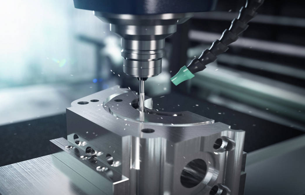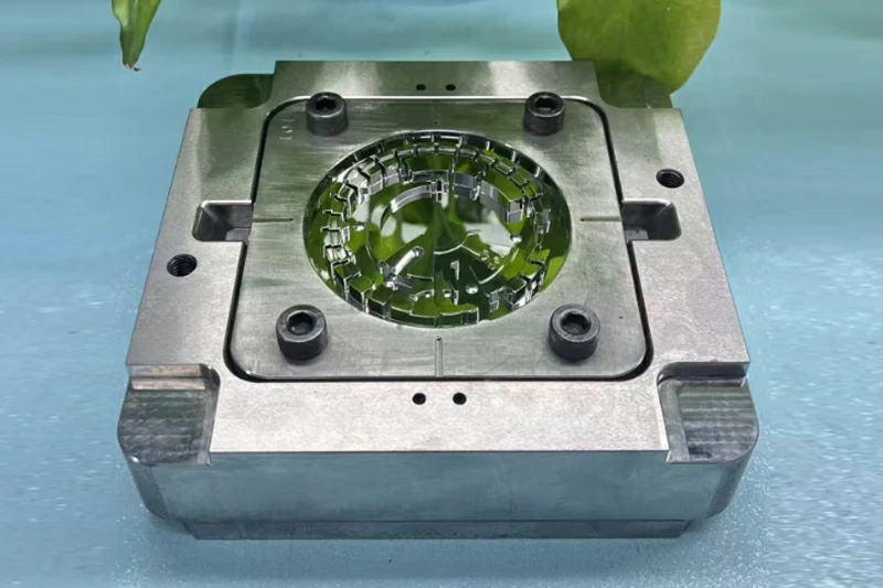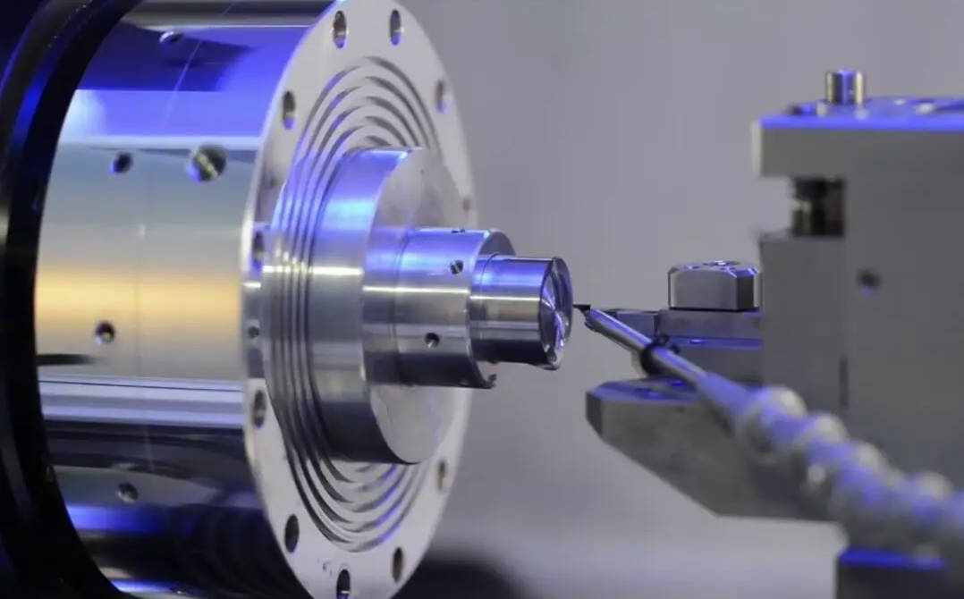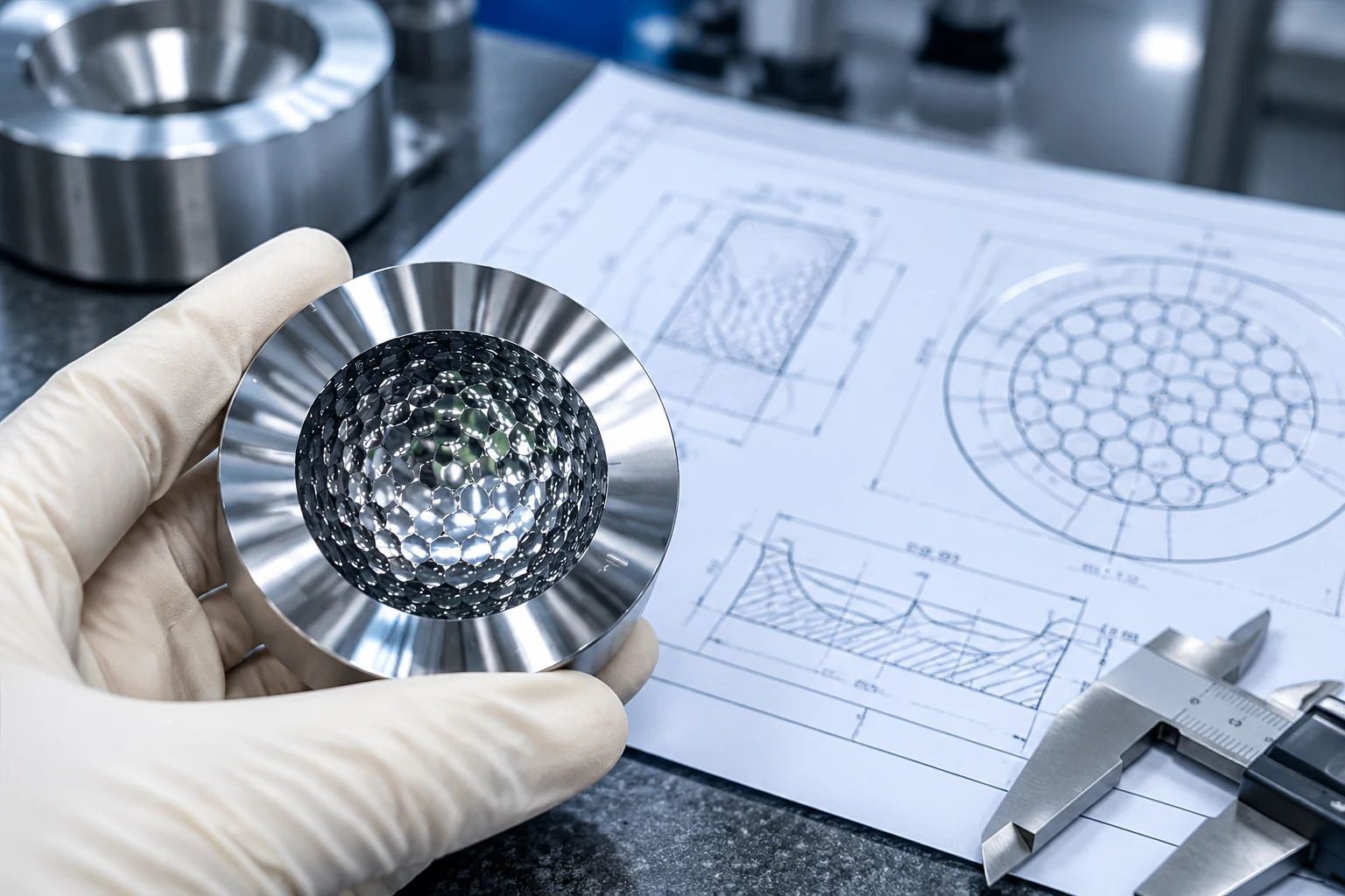
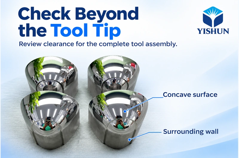
A small cutter appears able to reach the bottom of a mold insert. The tool tip fits the local radius, and the programmed contact point lies on the required surface. The feature looks machinable.
Then the holder approaches the cavity wall.
This is where a review based only on cutter diameter becomes incomplete. Tool holder clearance depends on the complete assembly, its orientation and the surrounding geometry throughout the movement.
For a mirror-finish insert, establishing access early helps avoid a late change to tooling, setup or process route after machining has already begun.
Separate Cutting Reach From Assembly Clearance
The cutting edge, tool neck, shank and holder occupy different spaces. A suitable tip does not establish clearance for everything behind it.
Start by identifying which part of the assembly comes closest to the cavity at each difficult location. The limitation may be a shoulder above the cutting edge, the holder nose or a wider section farther up.
Also distinguish cutting length from overall tool length. Extending a tool farther from the holder does not make its non-cutting shank suitable for cutting.
The review needs an actual tool assembly definition, not a simplified cylinder representing only the cutter.
Look Beyond the Finished Surface Model
A toolpath may clear the finished insert while approaching material that still exists at that stage.
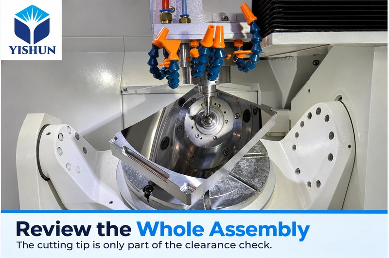
Include the relevant stock condition, surrounding walls, clamps and support features. A fixture that sits outside the cutting area can still obstruct the holder when the tool tilts.
Review the intermediate geometry rather than assuming every operation starts from the finished model. Material scheduled for removal later remains an obstacle now.
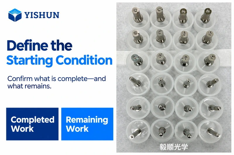
Where a customer supplies a partly machined insert, confirm its actual condition. A nominal drawing may not represent remaining stock, temporary features or an existing fixture arrangement.
Treat Longer Reach as a Trade-Off
Increasing tool projection may move the holder away from a wall, but it changes the cutting arrangement.
A longer unsupported length can reduce rigidity and make tool deflection or vibration more difficult to control. The significance depends on tool geometry, material, engagement and cutting conditions.
That matters when the surface must satisfy both geometric and finish requirements. A route that avoids contact but produces unstable cutting has not resolved the manufacturing problem.
Compare available tool forms, holder profiles and alternative orientations before assuming maximum extension is the answer. The shortest practical assembly is useful only when it also provides the required access.
Use Tilt to Resolve a Defined Obstruction
Five-axis machining for complex mold surfaces can provide additional orientation options. Tilting may move the holder away from one wall or allow a shorter tool to reach a surface.
However, the opposite side of the assembly may move toward another obstruction.
Evaluate the complete tilted position, including the holder and any nearby machine structure relevant to the setup. Check the available machine travel and rotary-axis limits as well.
Depending on the surface, a fixed indexed orientation may be sufficient; another area may require changing orientation during cutting. More axes create options, but they do not guarantee that every cavity becomes accessible.
Check the Journey Between Cutting Positions
Clearance at several selected points does not establish clearance along the connecting movements.
The assembly must enter the cavity, approach the cut, move between regions and withdraw. A position that is clear once reached may have no suitable approach from the preceding position.
Pay particular attention when orientation changes near tall walls or narrow openings. The holder sweeps through space while the cutting tip may move only a short distance.
Include linking and retract movements in the review. A visually convincing screenshot of the deepest cutting point cannot represent the complete operation.
Know What the Simulation Actually Includes
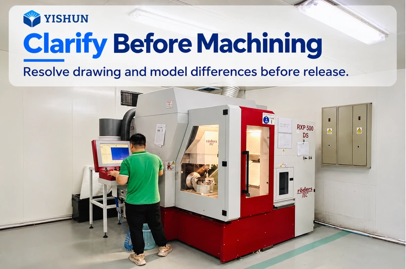
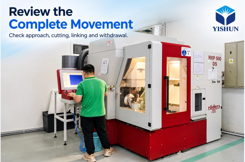
Before relying on a collision result, confirm the geometry and settings used to obtain it.
Is the holder included? Does the model match the intended assembly and projection? Are the relevant stock and fixture bodies present? Which movements and machine components are being evaluated?
An omitted object cannot contribute a collision warning. Likewise, a toolpath calculation and a machine-level simulation may answer different questions.
Use simulation as evidence within a defined scope. It does not replace checking that the physical setup matches the reviewed configuration or that the cutting process can achieve the required result.
Respond to an Access Limit Deliberately
If the planned assembly cannot reach safely, identify the limiting region before changing the route.
Possible responses may include another holder, a suitable reduced-neck tool, a different orientation or a revised setup. Some features may require another process.
These choices are not interchangeable. A setup change can introduce a new reference transfer; a different tool can change cutting behavior; another process can change allowance and finishing requirements.
Design changes require customer approval. Do not enlarge a radius, remove a wall or alter an optical boundary simply to make the available assembly fit.
Make the Access Review Useful to the Buyer
A useful review explains where access is restricted, what configuration was assessed and what decision remains.
For example, “the holder nose conflicts with the cavity wall during the approach” is more actionable than “this part is difficult.” It identifies a specific problem without promising that a longer cutter will solve it.
YISHUN Optical supports custom mirror-finish mold inserts, five-axis precision machining and ultra-precision component machining. To evaluate a restricted area, provide the current model, sectional views, material and critical surface requirements.
Include any fixed workholding constraints or features that cannot change. The objective is to confirm a workable assembly and movement sequence before cutting—not merely demonstrate that the tool tip can touch the surface.