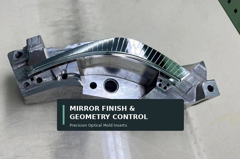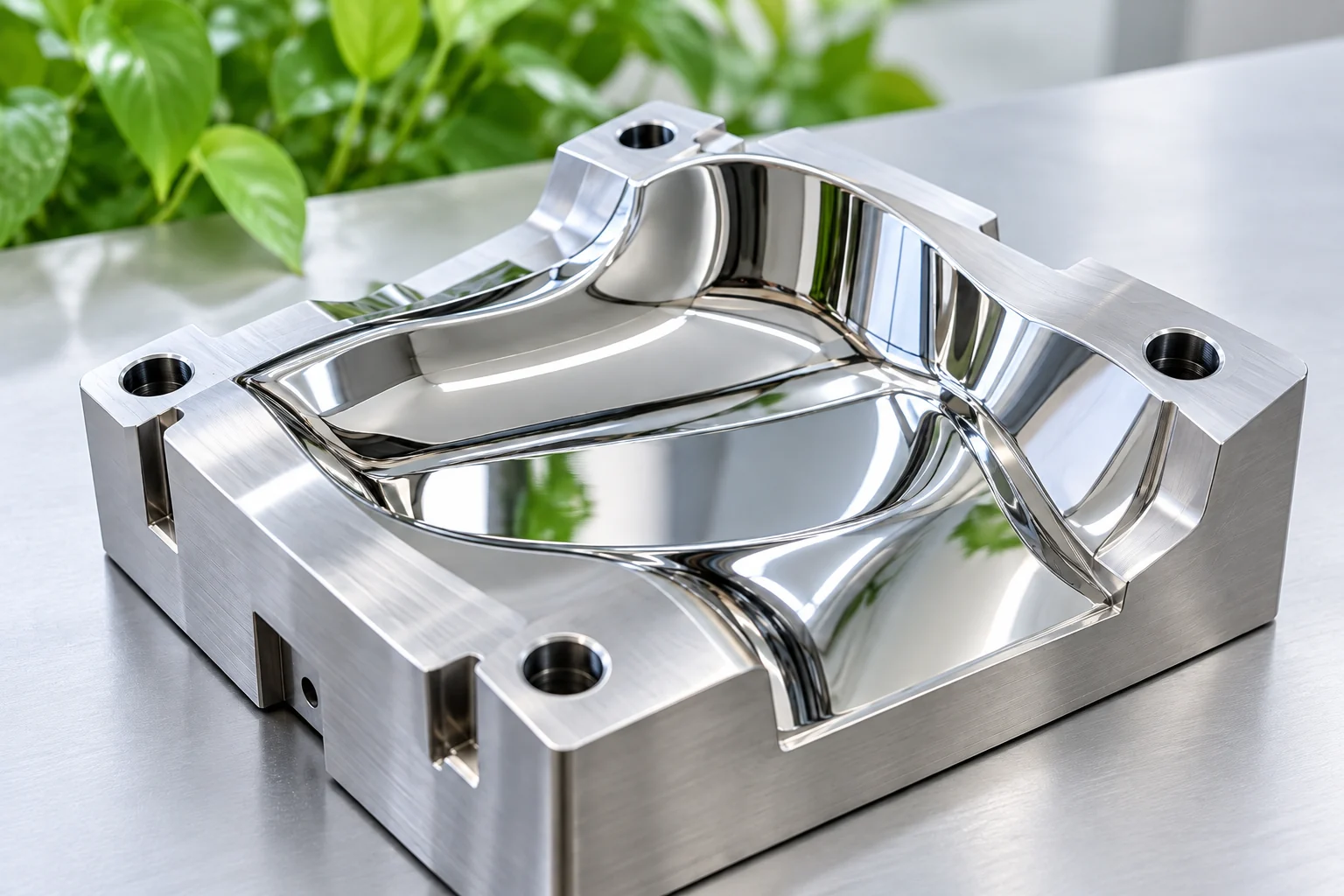
A precision mold insert can meet its drawing dimensions while it is still held in the machining fixture. But after the clamps are released, something changes.
A thin wall moves slightly. A narrow section springs back. A critical surface no longer sits exactly where the original model intended.
For customers, this is frustrating. The supplier has followed the drawing, machining has been completed, and inspection may even have looked acceptable during production. Yet the finished insert still has a geometry problem.
The difficulty is not necessarily the machine’s positioning accuracy.
Sometimes, the real problem is that the component does not have enough structural stability to maintain its intended geometry throughout machining and after release from the fixture.
Why Thin Sections Are Difficult to Machine
Thin walls behave differently from thick, rigid sections.
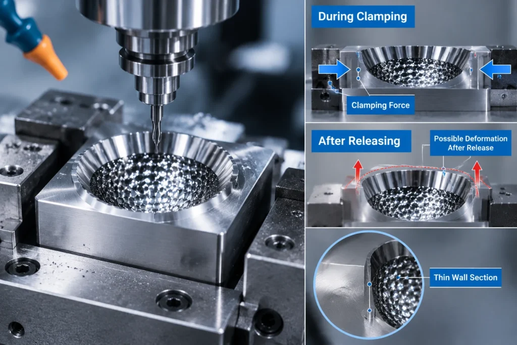
When cutting forces act on a thin area, the material can deflect slightly. If the fixture applies too much pressure, the component may also deform before machining even begins.
Several factors can contribute:
- Wall thickness and height: A tall, thin wall is generally more sensitive to lateral forces.
- Deep cavities: Removing surrounding material can reduce the stiffness of the remaining structure.
- Uneven material removal: Machining one side more heavily than another can change the component’s stress balance.
- Clamping pressure: Excessive or poorly distributed pressure can distort the workpiece.
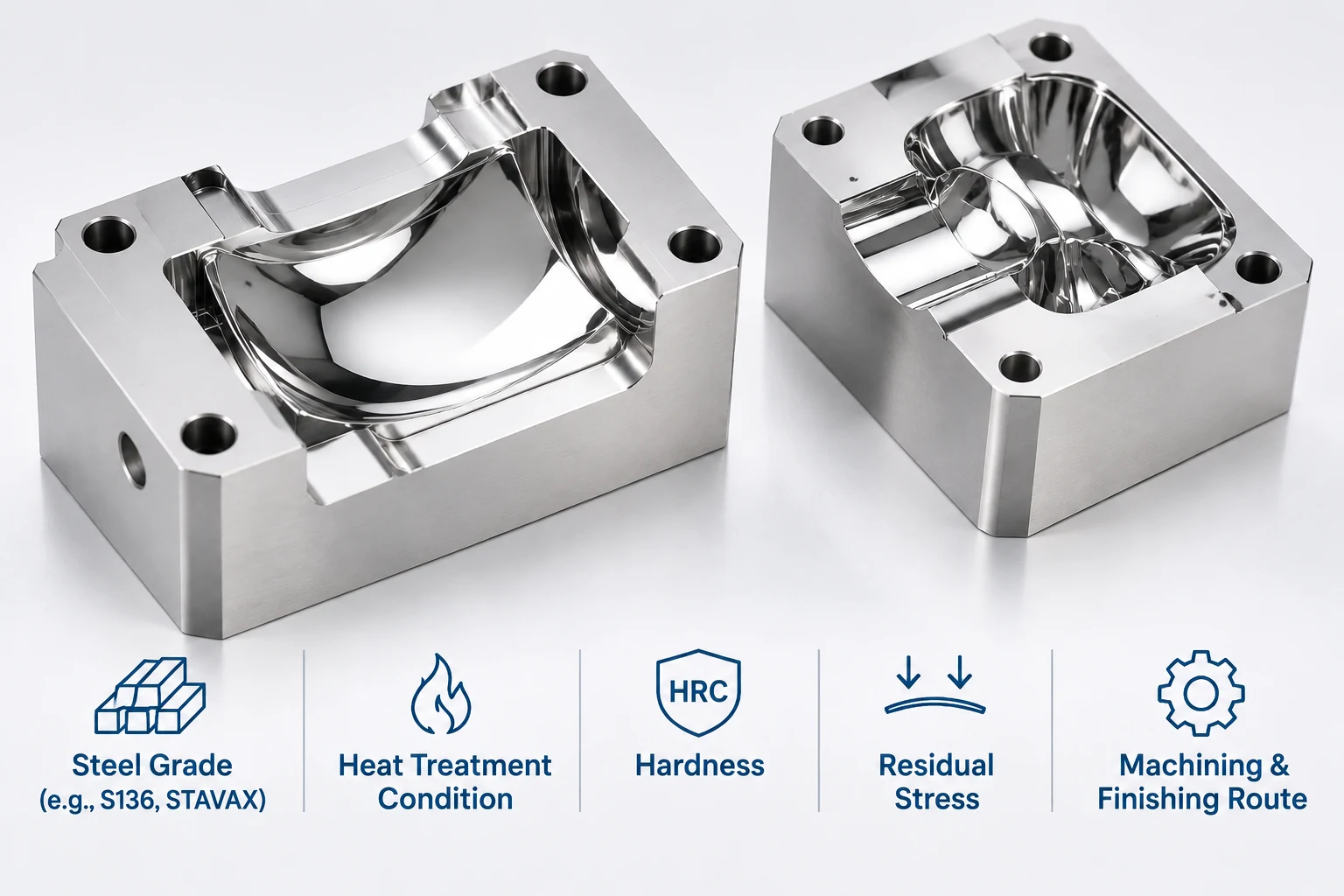
- Material condition: Residual stress and material properties can influence dimensional stability.
These factors can interact. A geometry that appears straightforward in CAD may become difficult once the surrounding material is removed.
Why Tighter Tolerances Do Not Automatically Solve the Problem
A common response to dimensional variation is to request tighter machine accuracy or more frequent inspection.
But this does not necessarily address the underlying cause.
Imagine a thin-walled insert that is slightly compressed during clamping. The machining operation may produce the intended geometry under that condition.
Once the fixture is released, the wall relaxes.
The measured geometry can then differ from the geometry recorded during machining.
In this situation, improving machine positioning accuracy alone will not eliminate the deformation.
We need to understand how the component behaves as a physical structure, not just how accurately the machine follows the programmed path.
What We Review Before Machining a Thin-Walled Insert
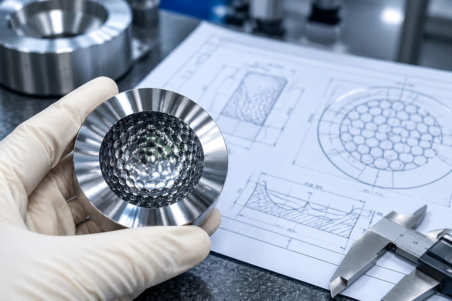
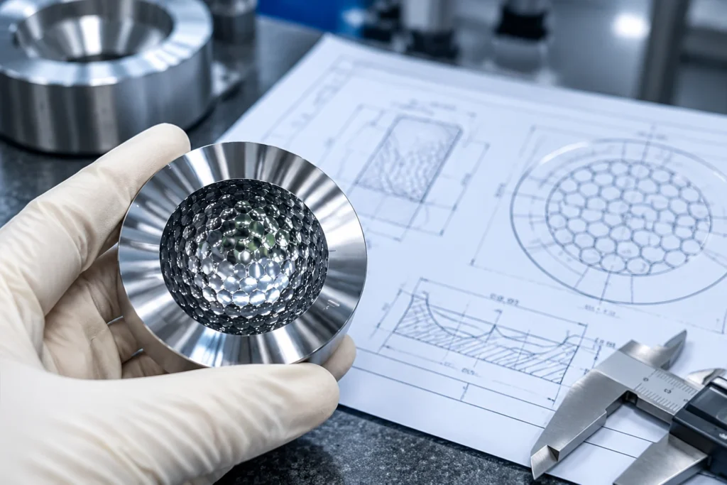
At Yishun Optical, when reviewing a component with delicate structural features, we would first examine the complete 3D geometry.
Our engineering review focuses on several areas.
1. Identify the vulnerable sections
We look at wall thickness, wall height, unsupported spans, cavity depth, and the relationship between thin sections and surrounding structures.
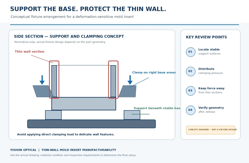
2. Review the supporting and clamping surfaces
The component needs stable positioning, but the fixture should not introduce unnecessary deformation.
We consider where the part can be supported, which surfaces can be used as references, and whether the clamping arrangement may influence the critical geometry.
3. Plan the material-removal sequence
For suitable geometries, a staged machining approach may help manage material removal and reduce the risk of releasing excessive deformation at the final stage.
The exact sequence depends on the material, geometry, and required accuracy.
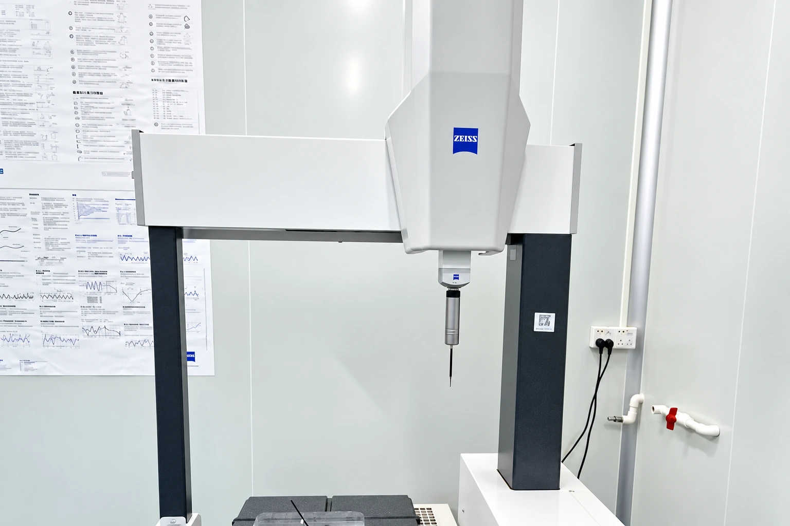
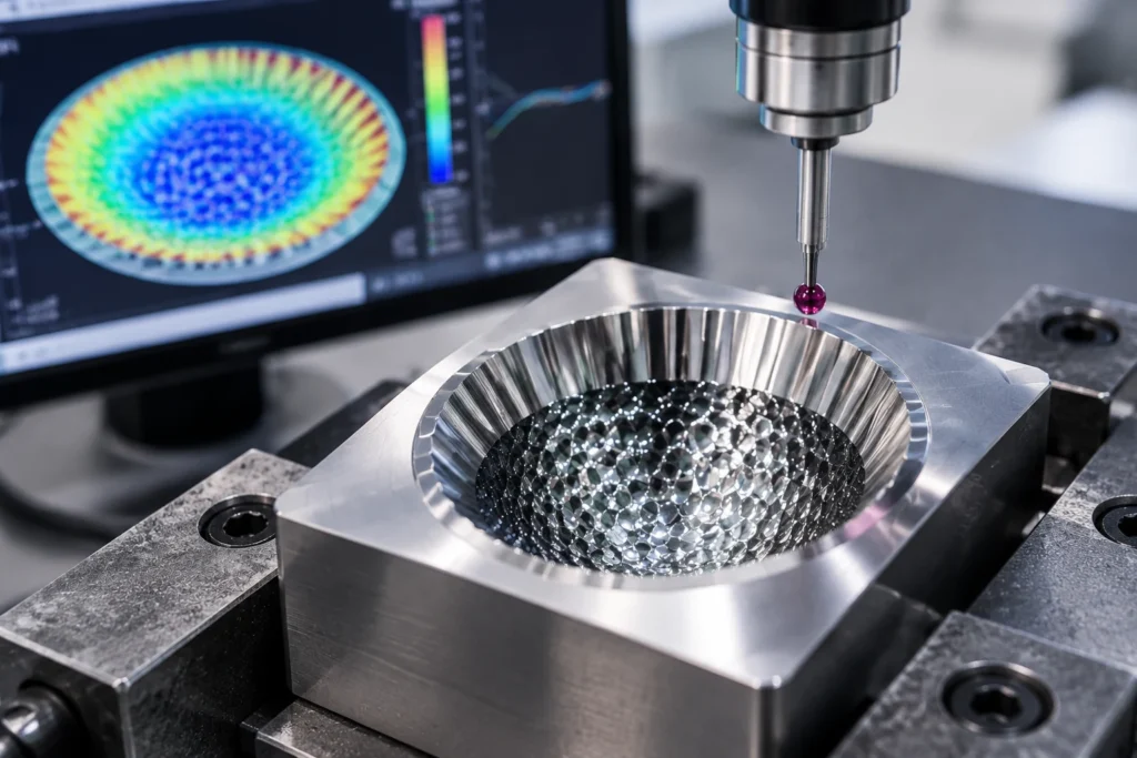
4. Check the component after release
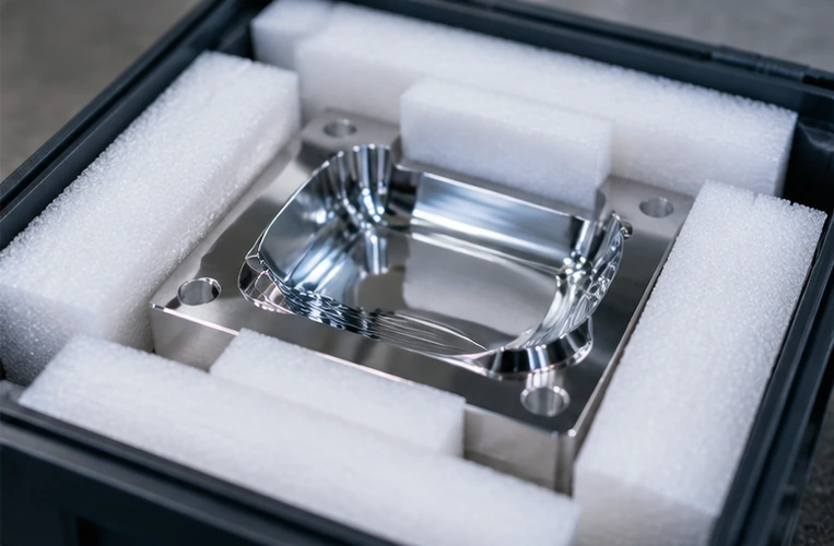
An important distinction is whether the finished geometry remains acceptable after the component is removed from its fixture.
Where deformation is a concern, final verification should reflect the agreed inspection condition rather than relying only on measurements taken during clamping.
Can the Design Be Improved Before Machining?
Sometimes, yes.
If the product’s functional requirements allow design adjustments, engineers may consider:
- Increasing the thickness of non-functional structural sections.
- Adding suitable support features.
- Reducing unnecessarily long unsupported walls.
- Reviewing the relationship between cavity depth and surrounding material.
- Clarifying which surfaces must remain dimensionally stable.
However, these changes should never be made simply to make machining easier.
For an optical mold insert, changing the geometry may also change the optical function or the final molded component.
Any design modification must therefore be reviewed and approved by the responsible design team.
If the geometry cannot change, the manufacturing approach must be evaluated around the existing design.
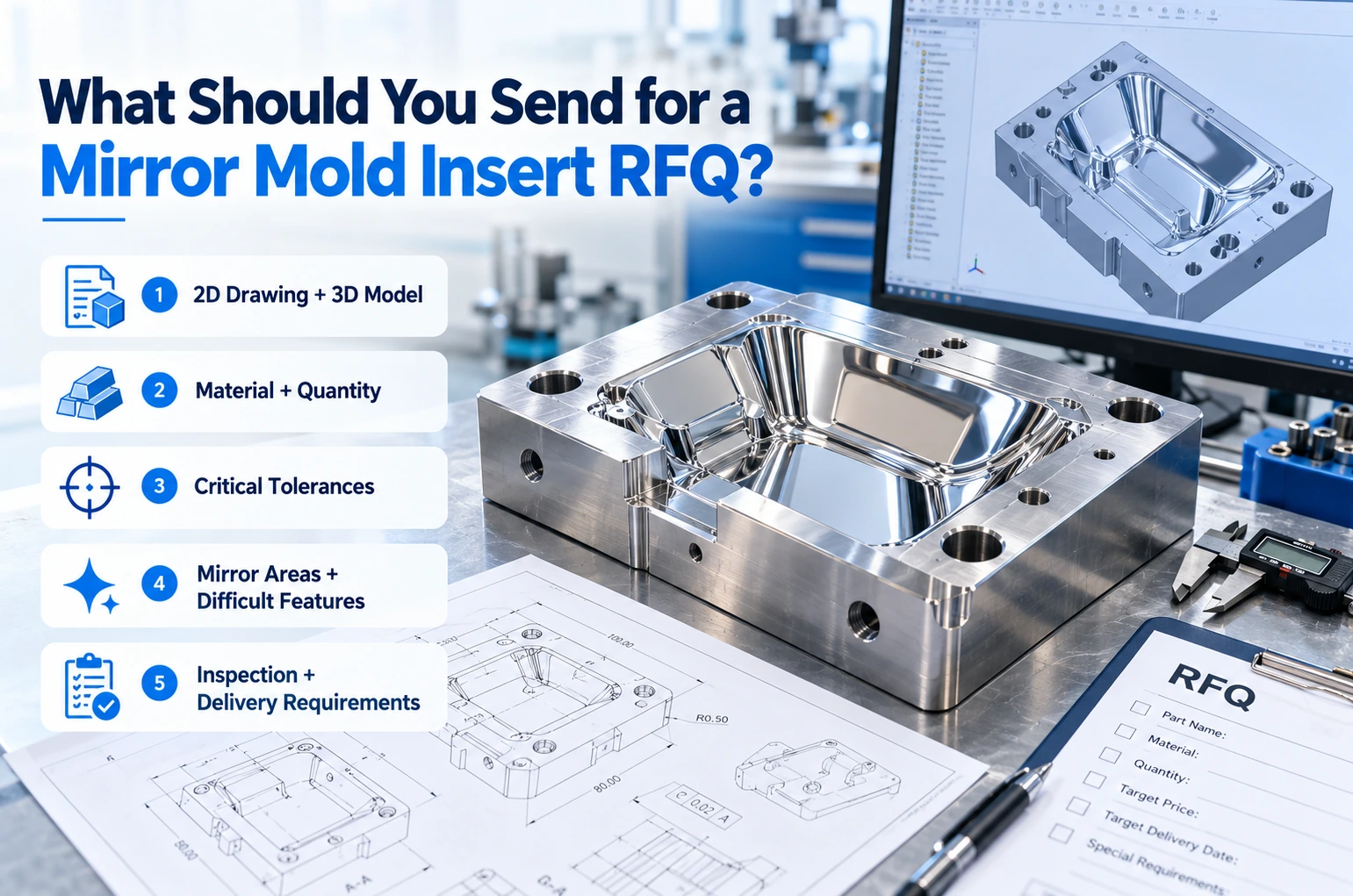
What Should You Provide for a Manufacturability Review?
If your mold insert contains thin walls, deep pockets, or delicate structural transitions, we recommend providing:
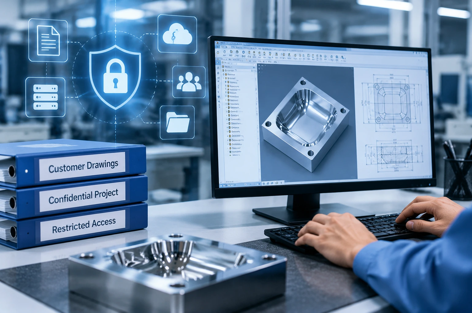
- The latest 2D drawing and 3D model.
- Material grade and heat-treatment condition.
- Critical wall thicknesses and dimensions.
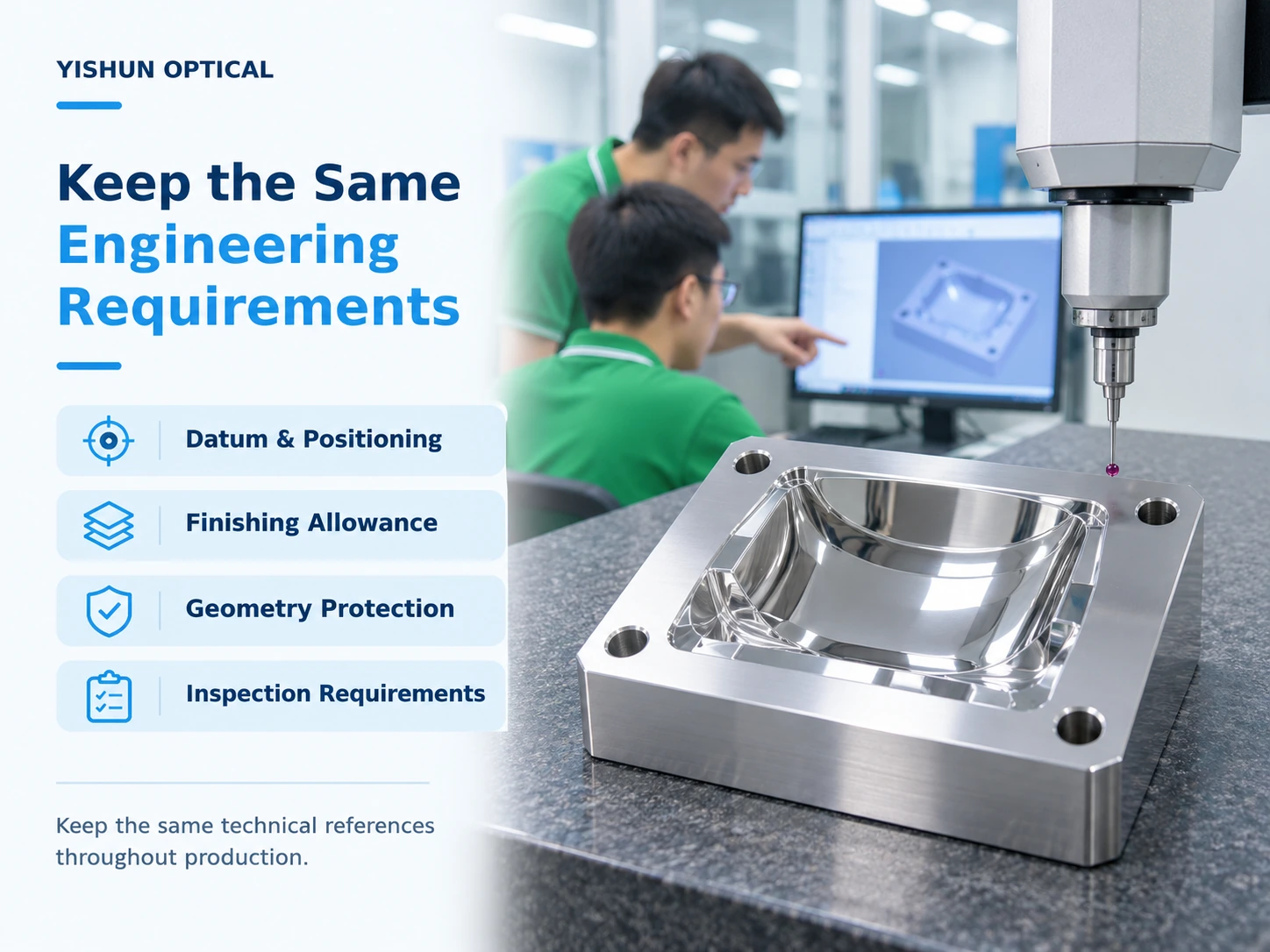
- Important datum and support surfaces.
- Required dimensional and form tolerances.
- Any known deformation or machining problems.
At Yishun Optical, we review geometry, material, machining accessibility, fixture requirements, and inspection priorities before confirming a suitable manufacturing approach.
We do not assume that every thin-walled component can be machined using the same method. Feasibility needs to be evaluated against the actual part.
A Stable Design Is the Starting Point for Accurate Machining
Thin-walled mold inserts are not difficult simply because their walls are small.
The real challenge is maintaining their intended geometry while material is removed, cutting forces are applied, and clamping conditions change.
A good machining strategy should therefore begin with the component’s structural behavior, not just its nominal dimensions.
If your next optical mold insert project contains thin sections or deformation-sensitive geometry, send us the drawing and 3D model.
We can review the potential manufacturing risks before machining begins.
The goal is not simply to machine the geometry correctly while the part is held in place. It is to help the finished insert maintain the geometry your application actually requires.