Precision mold core machining determines the dimensional fidelity, surface integrity, and part-to-part consistency of critical injection-molded components. Achieving sub-micron tooling tolerances requires tight coordination across multi-axis machine kinematics, material metallurgy, diamond cutting geometries, and ambient thermal stability. For tooling engineers and sourcing specialists, the difference between standard high-precision milling and ultra-precision single-point diamond turning (SPDT) dictates both manufacturing feasibility and unit economics.
This guide evaluates the mechanical boundaries of sub-micron machining, compares primary subtractive processes, outlines metallurgical requirements, examines thermal drift mitigations, and details metrology protocols for validating micro-featured mold inserts.
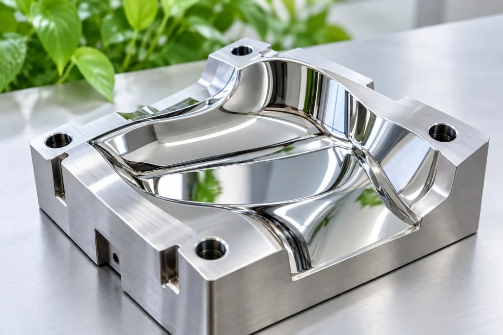
1. Defining Micron vs. Sub-Micron Precision in Mold Core Machining
In standard tooling production, high-precision mold core machining typically targets dimensional tolerances between ±5μm and ±10μm, with surface finishes refined through secondary bench polishing. In contrast, ultra-precision and sub-micron tooling pushes dimensional boundaries to ±1μm or lower, accompanied by sub-nanometer surface roughness thresholds (Ra<5nm) directly off the machine spindle.
| Machining Precision Tier | Dimensional Tolerance Window | Primary Limiting Factors |
|---|---|---|
| Standard Precision Tooling | ±5.0μm to ±10.0μm | Machine axis backlash, standard cutter runout, basic manual polishing distortion |
| High-Precision Micro-Milling | ±1.0μm to ±3.0μm | Micro-tool deflection, spindle runout, thermal growth of machine components |
| Sub-Micron / Ultra-Precision (SPDT) | <±1.0μm (down to ±0.1μm) | Material grain boundaries, sub-degree ambient thermal fluctuations, micro-vibrations |
At the sub-micron boundary, mechanical chip formation shifts from macro-shear deformation to micro-cutting within individual crystalline grains. Factors negligible in conventional machining—such as thermal expansion from ambient air shifts, microscopic spindle runout, and cutting edge radius—become dominant drivers of out-of-spec parts.
Precision Classification and Process Capabilities
| Precision Tier | Typical Dimensional Tolerance | Typical Surface Finish (Ra) | Secondary Bench Polishing Required? | Primary Industry Applications |
|---|---|---|---|---|
| Standard Precision | ±5.0μm to ±10.0μm | 0.2μm to 0.4μm | Yes (manual/mechanical stoning) | Consumer housings, automotive connectors, structural packaging |
| Micro-Milling Precision | ±1.0μm to ±3.0μm | 0.05μm to 0.15μm | Minimal (selective light buffing) | Fluidic diagnostic chips, micro-gear inserts, fine-pitch electronics |
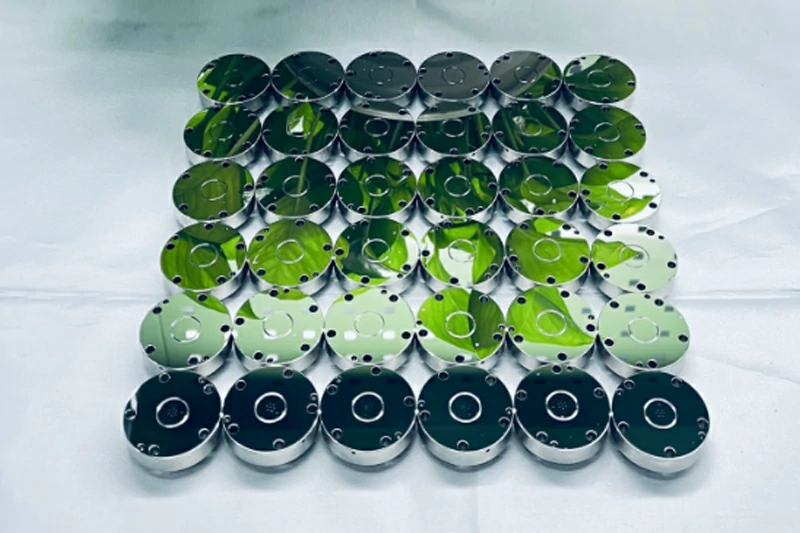
| Sub-Micron (SPDT / Ultra-Grinding) | <±0.5μm to ±1.0μm | <0.005μm (<5nm) | No (deterministic optical finish) | Imaging lenses, laser collimators, AR/VR light guides, diffraction gratings |
Note: Exact achievable tolerances depend on part geometry, material homogeneity, and ambient environmental controls; verify exact project parameters during engineering review.
2. Advanced Tooling & Machining Routes: SPDT, Ultra-Precision Milling, and Sinker EDM
Selecting the optimal machining route for a mold core depends on part geometry (rotational symmetry vs. freeform micro-cavities), material hardness, and whether optical-grade surface roughness is required.
| Process Route | Geometric Strengths | Compatible Materials | Achievable Surface Quality (Ra) | Primary Operational Constraints |
|---|---|---|---|---|
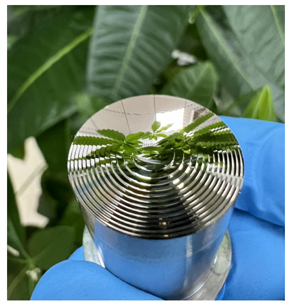
| Single Point Diamond Turning (SPDT) | Rotationally symmetric, aspheric, diffractive, and continuous optical surfaces | Electroless Ni-P, copper alloys, brass, aluminum, PMMA, cyclic olefins | Sub-nanometer (Ra<2nm to 5nm) | Unsuitable for direct steel machining due to chemical tool wear (graphitization) |
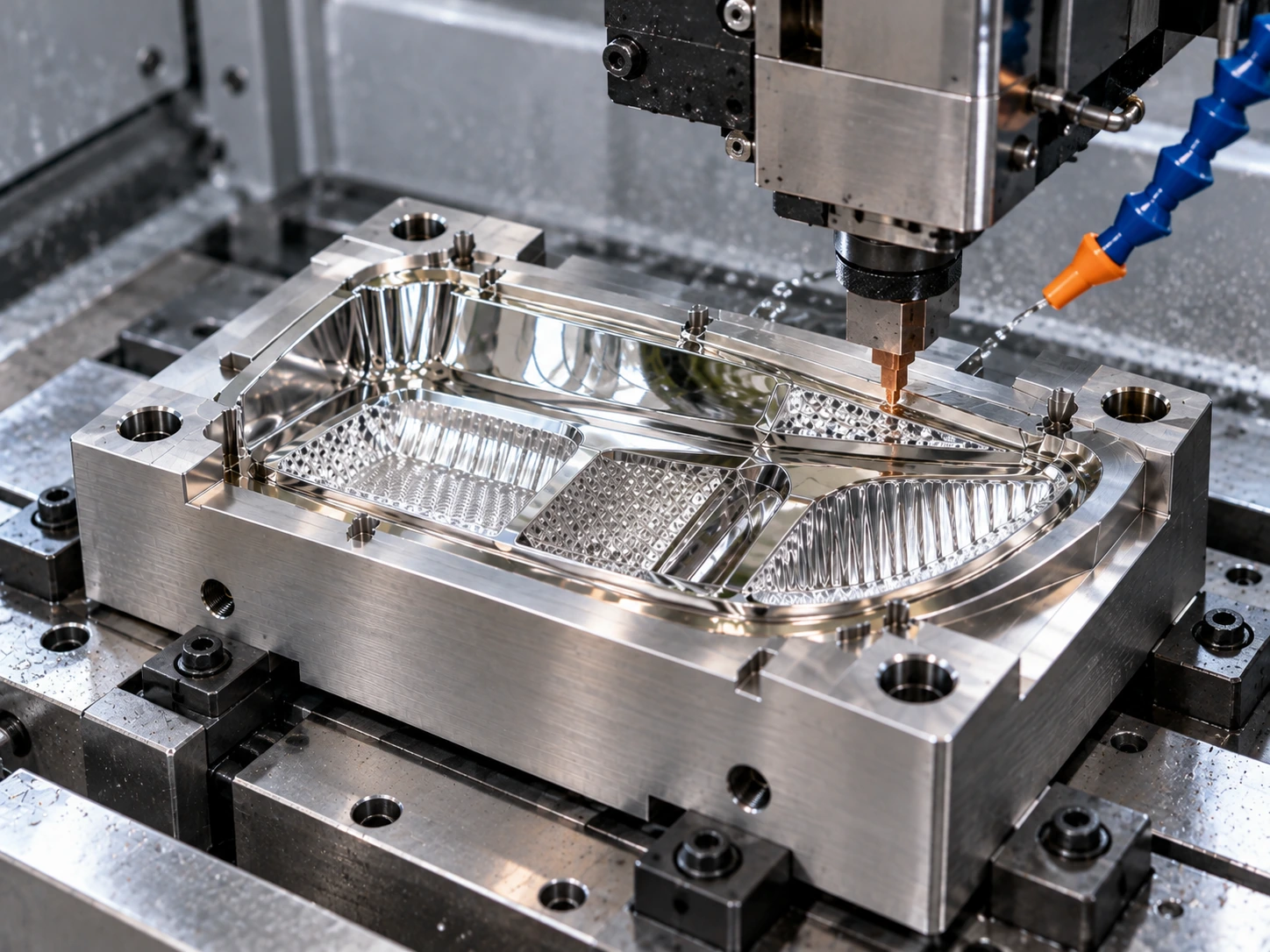
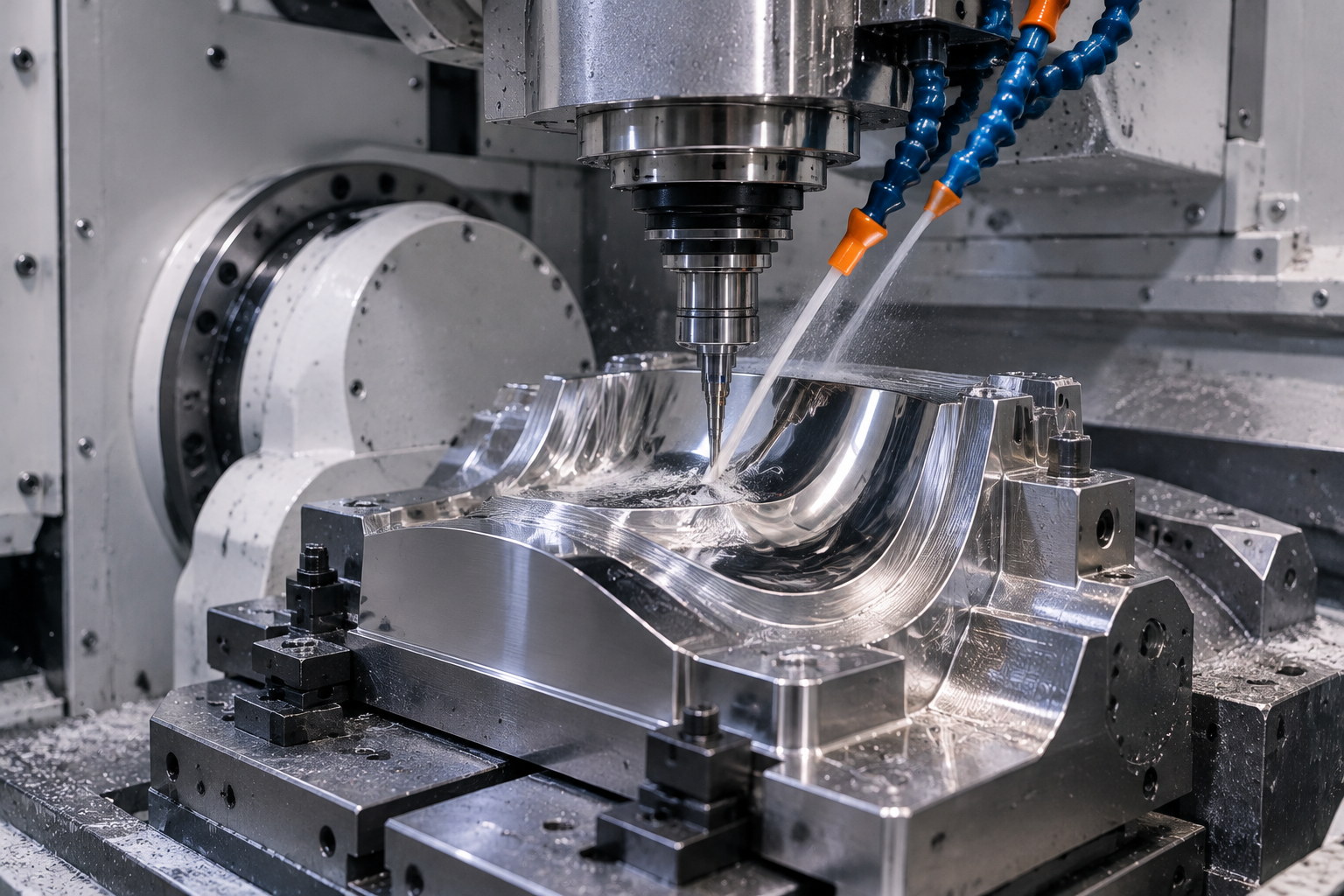
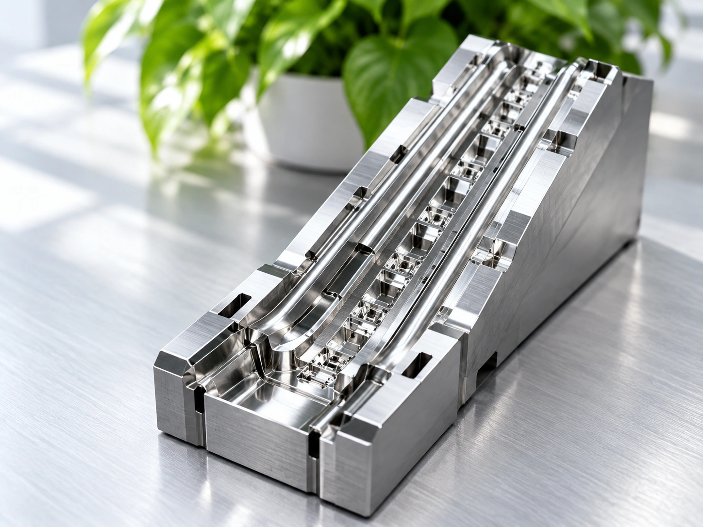
| Ultra-Precision 5-Axis Micro-Milling | Complex 3D freeforms, lenslet arrays, microfluidic channels, micro-ribs | Pre-hardened tool steels, stainless steels, copper, brass | Fine mechanical finish (Ra≈0.05μm to 0.15μm) | Micro-tool deflection; cutting speed limits on sub-millimeter tools (<0.1mm) |
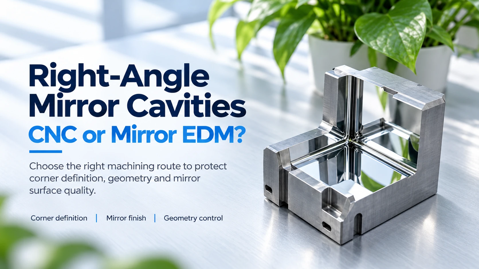
| Mirror Sinker & Wire EDM | High-aspect-ratio ribs, sharp internal radii (<0.05mm), deep blind slots | Hardened tool steels (>50HRC), cemented carbide, conductive alloys | Spark-eroded semi-mirror finish (Ra≈0.05μm to 0.10μm) | Leaves a recast layer (heat-affected zone); slower cycle times on ultra-fine discharge |
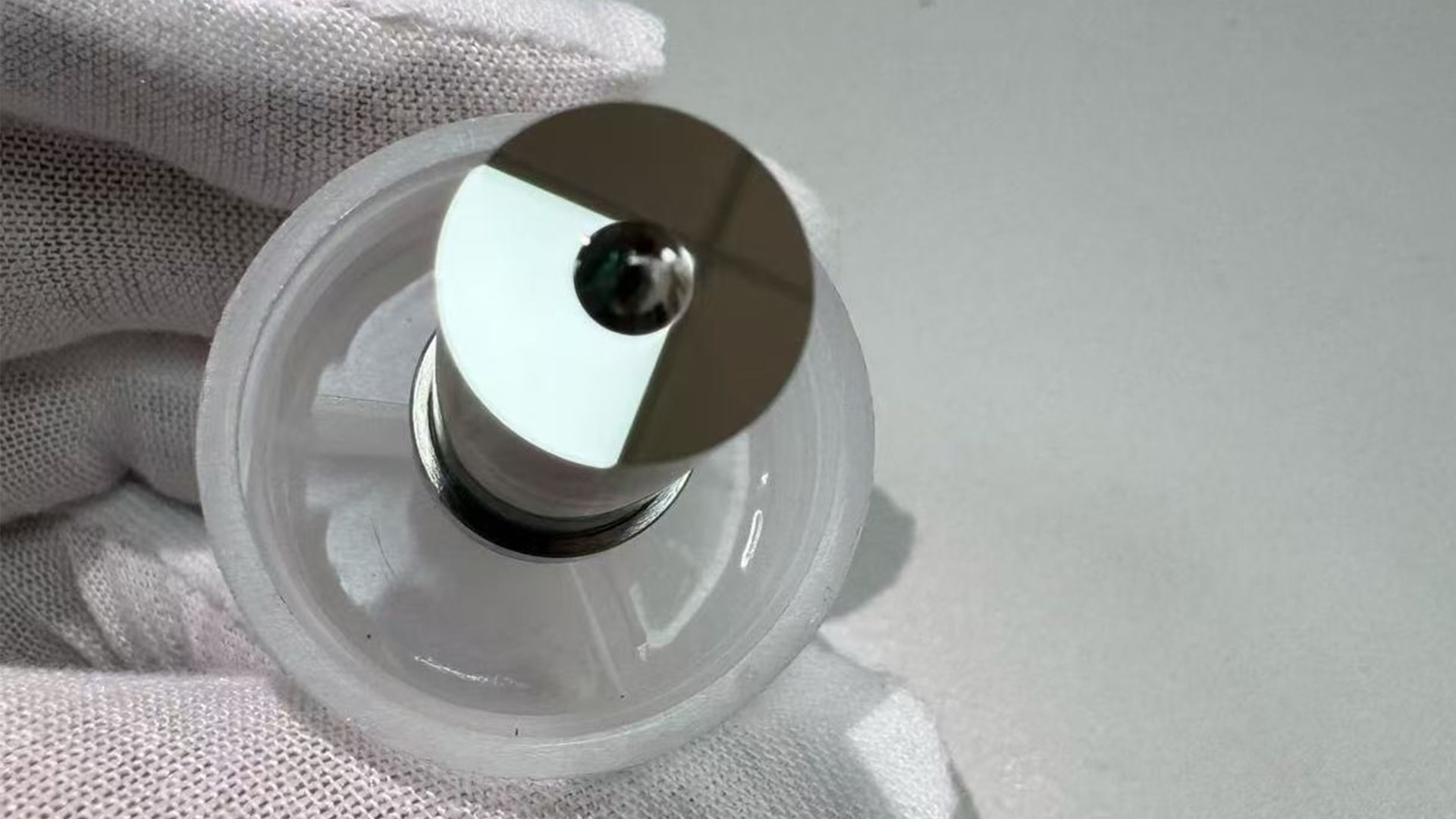
Single Point Diamond Turning (SPDT)
SPDT utilizes single-crystal natural or synthetic diamond cutting tools mounted on air-bearing spindles and hydrostatic slideways. It delivers nanometer-level form accuracy (Peak-to-Valley, PV<0.15μm) and mirror-smooth surfaces directly on the machine, eliminating manual hand-polishing that distorts precise optical profiles.
- Best Suited For: Spherical, aspheric, and freeform optical mold inserts; reflective mirrors; non-ferrous substrates.
- Limitations: Chemical affinity between carbon and iron causes rapid diamond graphitization, making SPDT unsuitable for direct cutting on ferrous tool steels without specialized ultrasonic vibration or protective coatings.
Ultra-Precision 5-Axis High-Speed Micro-Milling
Micro-milling employs micro-endmills (diameters ranging from 0.05mm to 1.0mm) running on air-bearing spindles at speeds up to 100,000RPM.
- Best Suited For: Non-axisymmetric freeform surfaces, micro-array lenses, lens arrays with distinct boundaries, and microfluidic channels.
- Limitations: Tool deflection occurs at microscopic shank diameters. Maintaining sub-micron tolerances requires predictive tool wear compensation and conservative feed rates.
Mirror Sinker EDM and Wire EDM
Electrical Discharge Machining vaporizes metal via controlled electrical sparks between an electrode and the workpiece.
- Best Suited For: Hardened tool steels (>50HRC), sharp internal corners, deep slots, and high-aspect-ratio ribs where mechanical cutting tools break.
- Limitations: Generates a microscopic recast layer (heat-affected zone). Even advanced nano-spark generators that yield mirror-grade finishes (Ra≈0.05μm) cannot match the continuous sub-nanometer surface integrity of SPDT.
3. Material Science in Sub-Micron Tooling: Overcoming Microstructural Instabilities
Achieving sub-micron mold core stability requires fine-grained material structures. Non-metallic inclusions, carbide segregation, and internal stresses cause microscopic pitting and unpredictable cutting forces when the depth of cut is smaller than the material grain size.
| Tooling Material | Microstructural Characteristic | Hardness Range | SPDT Compatibility | Typical Mold Core Use Case |
|---|---|---|---|---|
| Electroless Nickel Plating (Ni-P, 10–14% P) | Amorphous (non-crystalline, zero grain boundaries) | 48–52HRC (post-heat treatment) | Exceptional (Ra<2nm) | Plated layer (100–200μm) over steel cores for optical lenses |
| S136-ESR / Premium Stainless (e.g., Stavax) | Electro-slag remelted, homogeneous fine carbide distribution | 48–54HRC | Poor (requires micro-milling / EDM) | Micro-milled multi-cavity inserts requiring high corrosion resistance |
| Powder Metallurgy Tool Steel (PM Steel) | Rapidly solidified, sub-micron carbide grain structure | 56–62HRC | Poor for SPDT; optimal for micro-milling | High-wear micro-connectors, tight pitch semiconductor tooling |
| Oxygen-Free Copper (OFC) | Ultra-high purity, minimal oxide inclusion count | 80–100HB | Excellent (diamond turnable) | Micro-EDM electrodes, thermal inserts, infrared optical molds |
Electroless Nickel Plating (Ni-P, 10–14% Phosphor Content)
- Microstructure: Amorphous (non-crystalline) structure with zero grain boundaries.
- Machinability: Prevents cleavage fractures during diamond cutting, enabling optical surfaces with surface roughness Ra<2nm.
- Typical Implementation: Deposited as a 100μm to 200μm layer over a pre-machined stainless steel or copper substrate, then diamond-turned to final geometry.
Electro-Slag Remelted (ESR) Martensitic Stainless Steels (e.g., S136-ESR, Uddeholm Stavax ESR)
- Microstructure: Vacuum remelting minimizes sulfur, phosphorus, and non-metallic inclusions, yielding uniform carbide dispersion.
- Machinability: Recommended for micro-milling and mirror EDM where high core hardness (48–52HRC) and corrosion resistance against outgassing resins are required.
Oxygen-Free Copper (OFC) and High-Conductivity Copper Alloys
- Microstructure: High purity with minimal oxide inclusions.
- Machinability: Highly ductile and diamond-turnable; preferred for reflective infrared optics or high-conductivity thermal inserts in micro-injection molds.
4. Thermal Drift, Vibration, and Environmental Controls During Machining
In sub-micron manufacturing, the environment is an active variable in the machine loop. A standard tool steel mold core expands approximately 11.5μm per meter for every 1.0∘C rise in temperature. Over a 100mm mold core insert, a temperature shift of just 1.0∘C introduces an error of more than 1.1μm—completely consuming a sub-micron tolerance window.
| Environmental Control Variable | Target Standard for Sub-Micron Tooling | Mechanism of Error if Uncontrolled |
|---|---|---|
| Cleanroom Ambient Temperature | 20.0∘C±0.1∘C to ±0.2∘C | Volumetric thermal expansion/contraction of workpiece and linear scales |
| Cutting Fluid Temperature | Synchronized with machine frame (±0.05∘C) | Thermal gradient between tool-workpiece interface and machine base |
| Floor Vibration Isolation | Active pneumatic isolation; cutoff frequency <2–5Hz | Micro-waviness on optical surfaces; dynamic chatter marks |
| Spindle Dynamic Balancing | Radial runout <0.05μm (50nm) | Non-uniform depth of cut, accelerated edge chipping, form distortion |
- Active Thermal Compensation & Climate Control:
- Machine enclosures must operate within a cleanroom environment regulated to 20.0∘C±0.1∘C or ±0.2∘C.
- Coolant and dielectric fluid supply temperatures must be thermally matched to the machine frame to prevent internal gradients.
- Vibration Mitigation:
- Foundation isolation requires mounting machine tools on independent concrete inertia blocks isolated from external factory structural vibrations.
- Internal dampening relies on natural granite or cast mineral machine beds paired with active air-bearing isolation systems.
- Spindle Runout and Dynamic Balancing:
- Precision air-bearing spindles limit dynamic runout to under 0.05μm (50nm), avoiding surface chattering and micro-groove degradation.
5. Metrology & Quality Verification: Inspecting Sub-Micron Tolerances
A tolerance that cannot be measured cannot be validated. Validating sub-micron mold cores requires deterministic metrology that isolates surface form errors from surface roughness defects.
| Inspection Stage | Primary Metrology Equipment | Core Measurement Metrics | Primary Inspection Focus |
|---|---|---|---|
| 1. Thermal Stabilization | Temperature-controlled soaking bay (20∘C±0.1∘C) | Temperature equilibrium over 12–24h | Relieving thermal gradients prior to gauge contact |
| 2. Surface Roughness Validation | White Light Interferometer (WLI) / Optical Profilometer | Ra, Rq, Sa, sub-nanometer step heights | Non-contact verification of micro-roughness without stylus scratching |
| 3. Form Accuracy Verification | Laser Fizeau Interferometer / UA3P Profilometer | Peak-to-Valley (PV), RMS wavefront error | Aspheric/freeform contour conformity against CAD equations |
| 4. Coordinate & Datum Alignment | Micro-probe Tactile CMM (probing force <5mN) | True position, concentricity, datum parallelism | Precision alignment of mounting features and mold core registers |
Primary Measurement Instruments and Inspection Roles
- White Light Interferometry (WLI) / Optical Coherence Profilometry:
- Function: Non-destructive measurement of areal surface texture (Sa, Sq) and micro-step heights.
- Resolution: Sub-angstrom vertical resolution; captures high-frequency tool marks without mechanical surface scratching.
- Laser Fizeau Optical Interferometry:
- Function: Evaluates overall form error (PV, Peak-to-Valley) and wavefront aberration on spherical, flat, and aspheric optical mold cores.
- Key Metrics: Form accuracy confirmed against mathematical CAD surface equations down to fractions of a helium-neon laser wavelength (λ/10 to λ/20).
- Ultra-Precision Coordinate Measuring Machines (CMM):
- Function: Measures relational tolerances, true position, and geometric alignments across datums using low-force tactile micro-probes (<5mN).
- Operating Condition: Requires parts to undergo an equilibration “soak” period in a temperature-controlled metrology lab (20∘C±0.1∘C) for at least 12 to 24 hours prior to final sign-off.
6. Engineering Checklist: Preparing CAD and GD&T for Precision Machining
When transitioning from standard tool design to sub-micron core fabrication, vague drawing notes (such as “polish to mirror finish”) introduce manufacturing ambiguity and cost creep. Clean, unambiguous datum structures and clear functional callouts are essential.
Pre-Procurement Engineering Review Checklist
- [ ] Datum Scheme Grounding: Ensure primary, secondary, and tertiary datums are placed on ground, accessible surfaces rather than curved, freeform functional surfaces.
- [ ] Internal Corner Radii Allocation: Specify internal radii of at least 0.15mm to 0.20mm where possible; micro-endmills with diameters below 0.1mm exhibit sharp tool-wear curves.
- [ ] Substrate vs. Plating Thickness: If using nickel-phosphorus (Ni-P) plating for SPDT, explicitly define both the pre-plate steel dimensions and the finished, turned coating thickness.
- [ ] Separation of Form Error and Roughness: Distinguish between permissible profile form error (PV≤0.3μm) and surface finish (Ra≤4nm) on the blueprint.
- [ ] Assembly and Draft Angles: Confirm release draft angles on vertical micro-features; parts molded from mirror-finish cores without sufficient draft (>1∘) can vacuum-lock or scratch upon ejection.
7. Strategic Manufacturing Consultation for Precision Tooling
Achieving reliable sub-micron core performance demands early coordination between product designers and manufacturing teams. Integrating design-for-manufacturability principles early in development helps align part tolerances with machine and material capabilities.
Reviewing your design models, datum selections, and GD&T requirements before cutting metal prevents compounding runout errors, shortens testing cycles, and avoids expensive scrap during final tooling trials.
Key Takeaways
- The Sub-Micron Threshold: Crossing from standard precision (±5μm) to sub-micron tooling (<±1μm) shifts the dominant variables from mechanical cutting kinematics to material microstructure, thermal expansion, and nano-scale tool wear.
- Process Alignment: Use SPDT for rotationally symmetric, continuous optical surfaces requiring sub-nanometer finishes; use 5-axis ultra-precision micro-milling for complex 3D freeform cavities; use mirror sinker EDM for deep ribs in hardened steels.
- Material Matters: Avoid standard commercial steels for optical mirror surfaces. Opt for amorphous Electroless Nickel Plating (Ni-P) for diamond cutting, or ESR powder-metallurgy stainless steels for micro-milled cavities.
- Environmental Control: Without active ±0.1∘C shop floor temperature control and vibration isolation, sub-micron tolerances cannot be maintained or verified.
- Metrology Rigor: Pair non-contact white light interferometry (for nanometer surface roughness) with micro-probe CMMs (for geometric positioning) following a full thermal stabilization soak.
FAQ
Can single-point diamond turning (SPDT) cut steel mold cores directly?
Standard single-point diamond tools cannot cut ferrous alloys like steel directly under normal machining conditions. The chemical affinity between iron and carbon induces rapid chemical wear (graphitization) of the diamond tool tip within seconds of contact. To achieve diamond-turned finishes for steel mold components, manufacturers either apply an amorphous electroless nickel-phosphorus (Ni-P) plating over the steel core and diamond-turn the nickel layer, or use ultrasonic vibration-assisted machining systems with specialized CBN (cubic boron nitride) tooling.
What is the primary operational difference between micron and sub-micron tooling costs?
Tooling costs increase sharply when transitioning from micron to sub-micron specifications. Sub-micron tooling requires dedicated cleanroom environments, specialized air-bearing machinery, custom cutting tools, conservative feed rates, and extended thermal stabilization periods. Furthermore, non-destructive optical metrology cycles take significantly longer than standard mechanical inspection, which increases overall machine hour costs.
How does thermal expansion affect mold cores during mass injection molding?
A mold core machined to sub-micron tolerances at 20∘C will expand when exposed to production mold operating temperatures (often 60∘C to 140∘C, depending on the resin). Tooling engineers must calculate the material’s coefficient of thermal expansion (CTE) and apply a uniform scaling offset during CAM programming. This ensures the mold cavity settles into its exact target dimensions when operating at steady-state injection temperatures.