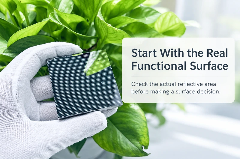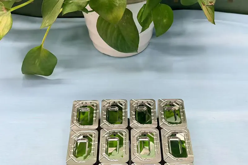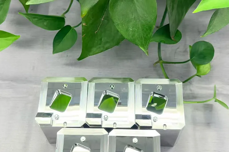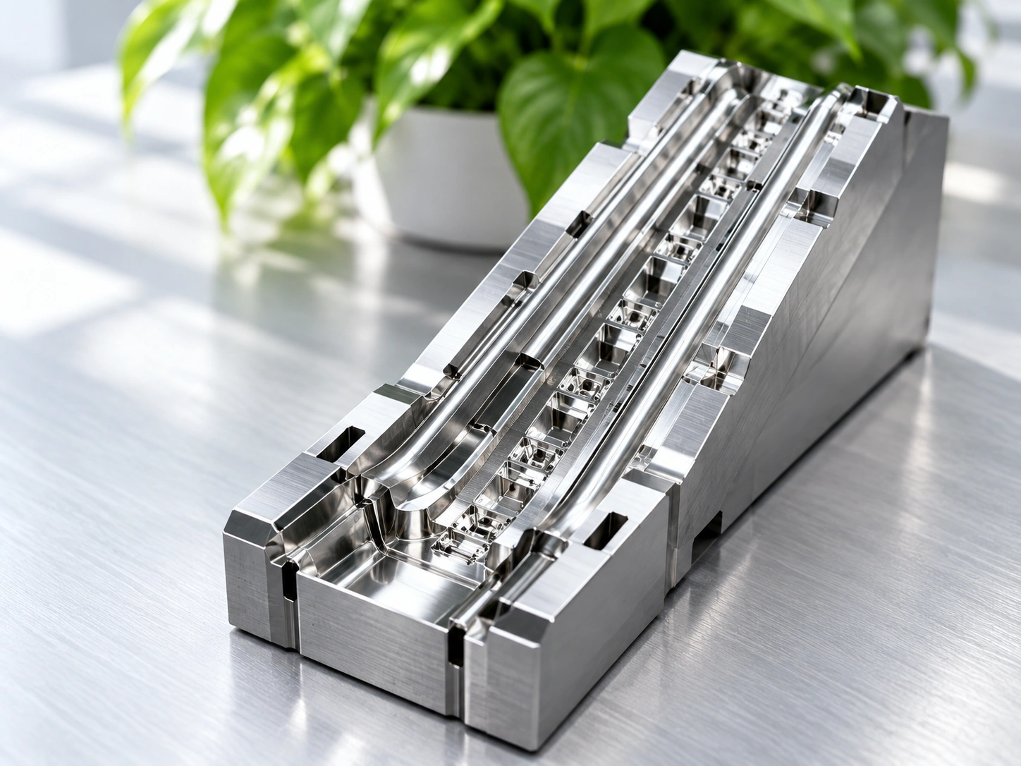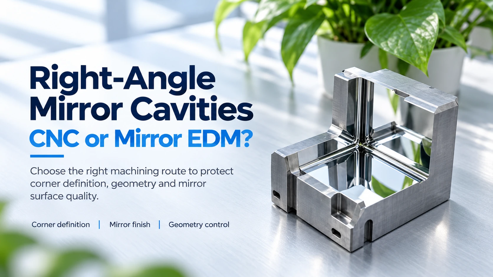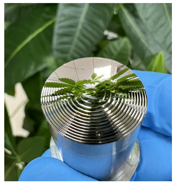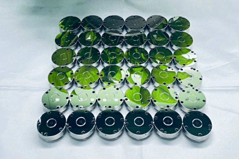
A small precision part can look simple on a drawing.
Then the machining starts.
A feature that is only a few millimeters wide may contain a narrow groove, a small radius, a tiny step, a micro cavity or a mirror-finish surface. The overall component may be easy to hold in your hand, but keeping every local feature within tolerance can be much harder than machining a much larger part.
This is where many small precision components become difficult.
The problem is not simply making the part smaller.
It is maintaining the geometry, surface quality and dimensional relationship of every small feature at the same time.
For applications such as optical mold inserts, medical components, precision sensors and automotive optical structures, a small deviation in one local area can affect the function of the entire component.
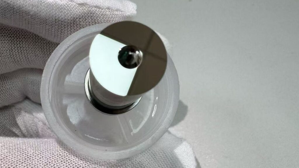
The Smaller the Feature, the Less Room There Is for Error
On a large component, a small machining error may sometimes remain within a non-critical area.
On a micro-scale component, there may be no non-critical area.
A 0.05 mm tool radius, a narrow groove or a small transition can represent an important functional feature.
If the tool is too large, the feature cannot be generated correctly.
If the tool is too flexible, vibration can appear.
If the tool overhang becomes excessive, dimensional stability becomes harder to maintain.
And if the feature later needs aggressive polishing, the original geometry can change again.
This is why ultra-precision machining is not simply about using a smaller cutting tool.
The entire machining condition has to become more controlled.
Small Features Need Stable Tool Control
One of the first challenges is tool selection.
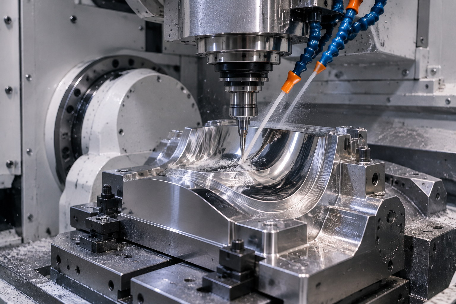
Small tools have limited rigidity. As the tool diameter decreases, the relationship between tool stiffness, cutting force, spindle condition and tool overhang becomes increasingly important.
A machining strategy that works well for a conventional mold component may not be suitable for a small precision feature.
For micro-scale structures, we may need to consider:
- Tool diameter and cutting edge geometry
- Tool runout
- Tool overhang
- Spindle stability
- Cutting depth
- Feed rate
- Tool-path continuity
- Coolant or cutting-fluid behavior
- Workpiece clamping and vibration
The objective is not to remove material as quickly as possible.
The objective is to remove the required material without allowing the machining process to change the geometry we are trying to create.
This becomes especially important when the component contains several small features that must remain aligned with each other.
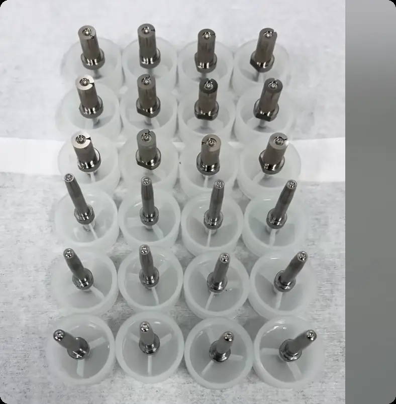
Complex Geometry Can Make a Small Part Even More Difficult
Size is only one part of the problem.
A small component can also contain several different geometries within a very limited space.
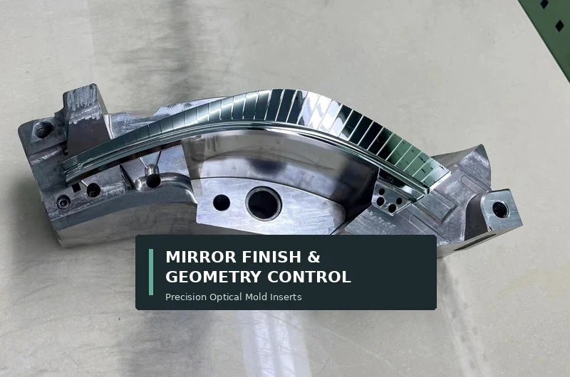
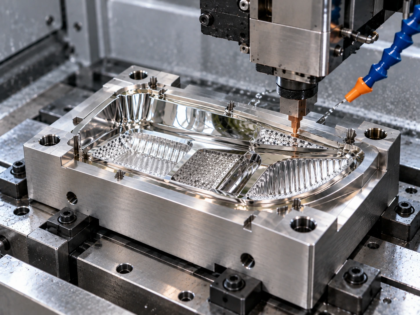
For example, one precision insert may combine a curved optical surface, a narrow groove, a small radius and several mechanical reference features.
Each feature may be machinable individually.
The difficulty comes from machining them together while preserving their relationship.
This is why we review the complete geometry before choosing a machining route.
For optical applications, the optical surface cannot be considered separately from the surrounding structure. Tool access, transition areas, edge definition and datum relationships all influence the final result.
Our AR/VR optical mold machining capability follows the same principle: the difficult part is often not the overall size of the insert, but the small local areas where geometry changes quickly.
Surface Finish Becomes More Sensitive on Small Components
A small component may also require a very high-quality surface.
This creates another challenge.
A surface can look bright and smooth while still having form deviation, local waviness or dimensional changes.
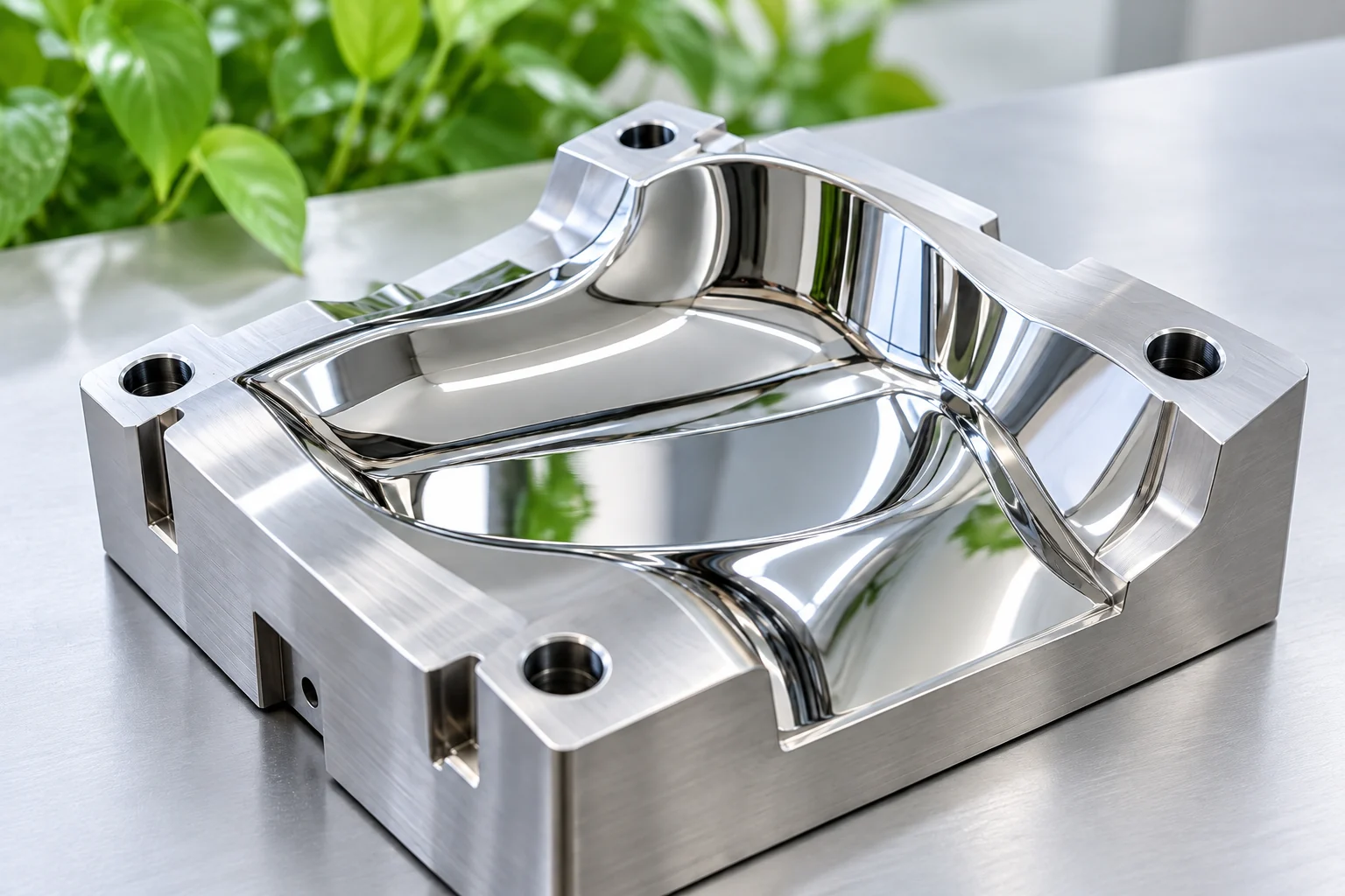
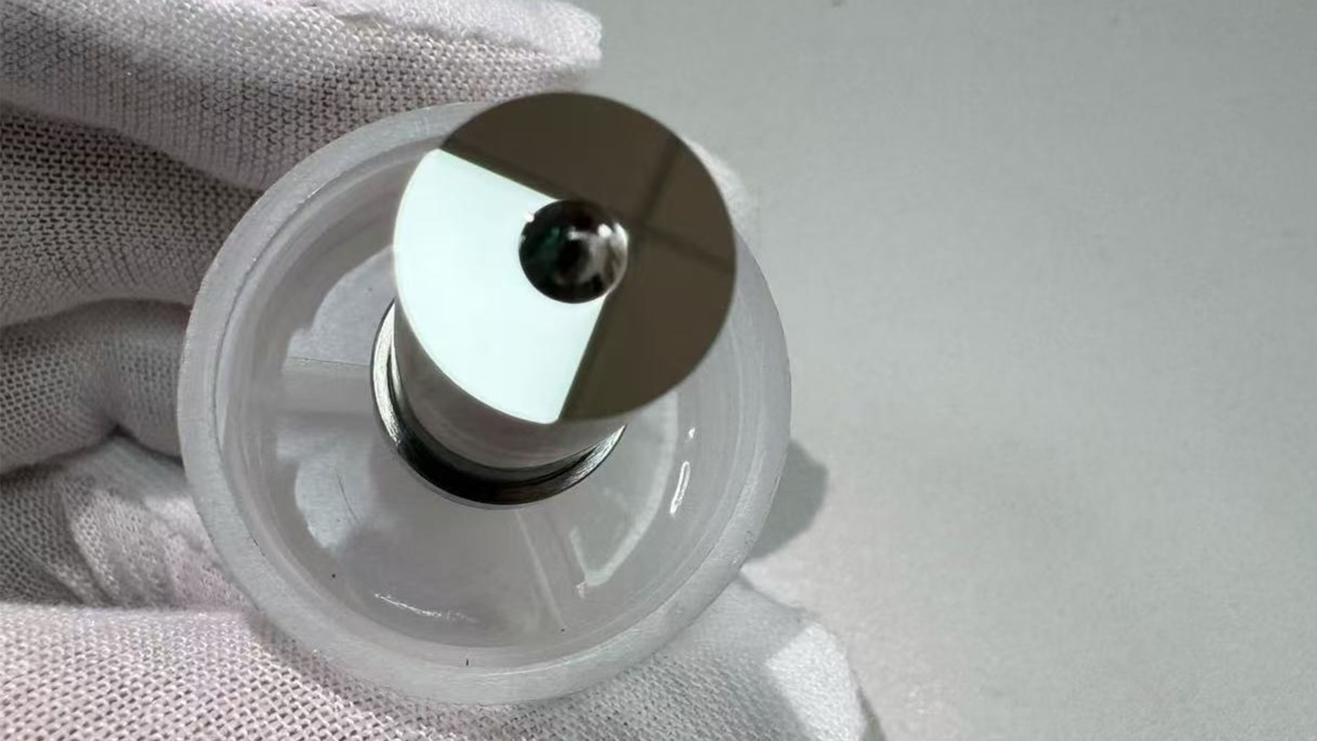
For a mirror-finish mold insert, surface quality cannot be separated from geometry.
If too much material is removed during finishing, a small radius can become larger.
A sharp boundary can become softer.
A narrow functional surface can change shape.
And once the original geometry has been altered, simply making the surface brighter does not solve the problem.
This is why we treat polishing as a controlled finishing stage rather than a way to correct an unfinished geometry.
Our approach is to generate as much of the required geometry and surface quality as practical during machining, then use controlled finishing where it actually adds value.
For suitable materials and rotational geometries, single-point diamond turning can provide another route for generating highly controlled precision surfaces.
Small Radii Need to Be Protected
Small radii are another common source of problems.
A radius that looks insignificant on a drawing may have a direct functional purpose.
It may control how two surfaces transition.
It may define an optical boundary.
It may affect how a molded feature is replicated.
Or it may simply be part of a critical mechanical interface.
The risk is that the radius becomes larger during finishing.
This can happen when polishing pressure, tool access or abrasive action is difficult to control.
For that reason, we pay particular attention to small-radius features before the finishing stage.
Our small-radius mold insert machining approach focuses on creating the geometry through machining rather than relying on manual polishing to define the final radius.
The principle is simple:
Polishing should refine the surface. It should not create the geometry.
Dimensional Stability Matters as Much as Individual Accuracy
Another problem with small precision components is that one dimension may be correct while the relationship between several dimensions is not.
For example:
A groove may have the correct width, but its position may be slightly wrong.
A cavity may have the correct depth, but its surrounding reference may have shifted.
A small optical feature may have the correct surface finish, but its position relative to the mechanical datum may not be correct.
These differences can be difficult to see by visual inspection.
That is why inspection needs to follow the actual function of the component.
Depending on the project, we may need to check dimensional relationships, form, surface condition, critical radii and datum positions rather than relying on a single measurement.
For very small parts, measurement conditions themselves also matter.
Temperature, handling, cleaning and the transfer between machining and inspection can influence dimensional results. Temperature control in ultra-precision machining therefore becomes part of the overall precision-control discussion rather than an isolated machine-room issue.
Repeatability Is the Real Test
Making one small precision part correctly is only the beginning.
The more important question is whether the same result can be produced again.
This becomes critical when customers need multiple inserts, repeated precision components or several identical micro features.
A process that depends heavily on manual adjustment may produce a good first piece but become difficult to reproduce consistently.
For this reason, we focus on process stability:
- Consistent tool condition
- Controlled machining parameters
- Stable fixturing
- Defined datum relationships
- Controlled finishing
- Repeatable inspection
- Clear acceptance criteria
The goal is not simply to achieve a good-looking sample.
It is to establish a machining process that can produce the same geometry repeatedly.
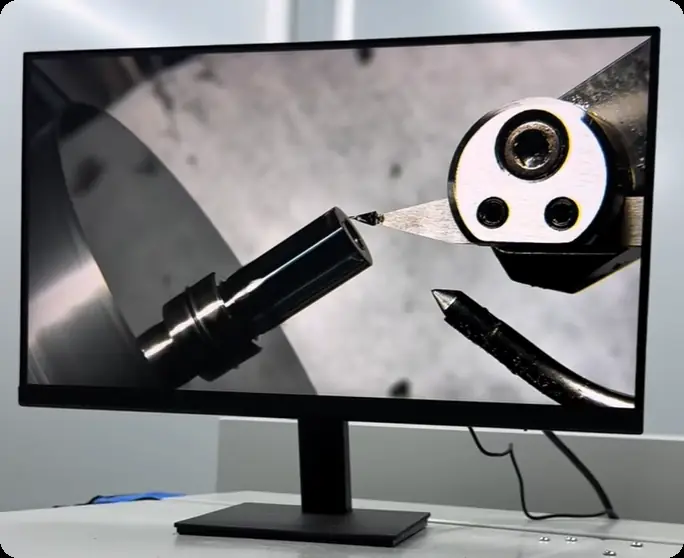
Small Does Not Mean Simple
When a customer sends us a very small precision component, we do not judge the project only by its overall dimensions.
We look at the smallest feature.
Then we look at what surrounds it.
Can the tool reach it?
Can the tool remain stable?
Is there enough space for chip evacuation?
Will finishing tools be able to access the area?
Which dimensions must remain unchanged after finishing?
How will the final feature be measured?
These questions often determine whether a small component is straightforward or genuinely challenging.
For suitable projects, YISHUN Optical combines ultra-precision machining, high-speed precision milling, five-axis machining, controlled mirror finishing and precision inspection according to the actual geometry.
The process is selected around the part—not the other way around.
When a Small Precision Part Becomes Difficult
If your component contains micro-scale features, small radii, narrow grooves, complex curved surfaces or mirror-finish areas, the most useful discussion should happen before machining begins.
Send us the 2D drawing, 3D model, material, critical dimensions and surface requirements.
We can review the smallest and most sensitive features first, identify where machining or finishing may create risk, and then determine a practical manufacturing route.
Because with small precision components, the challenge is rarely making the part small.
The challenge is making every small feature stay where it belongs.