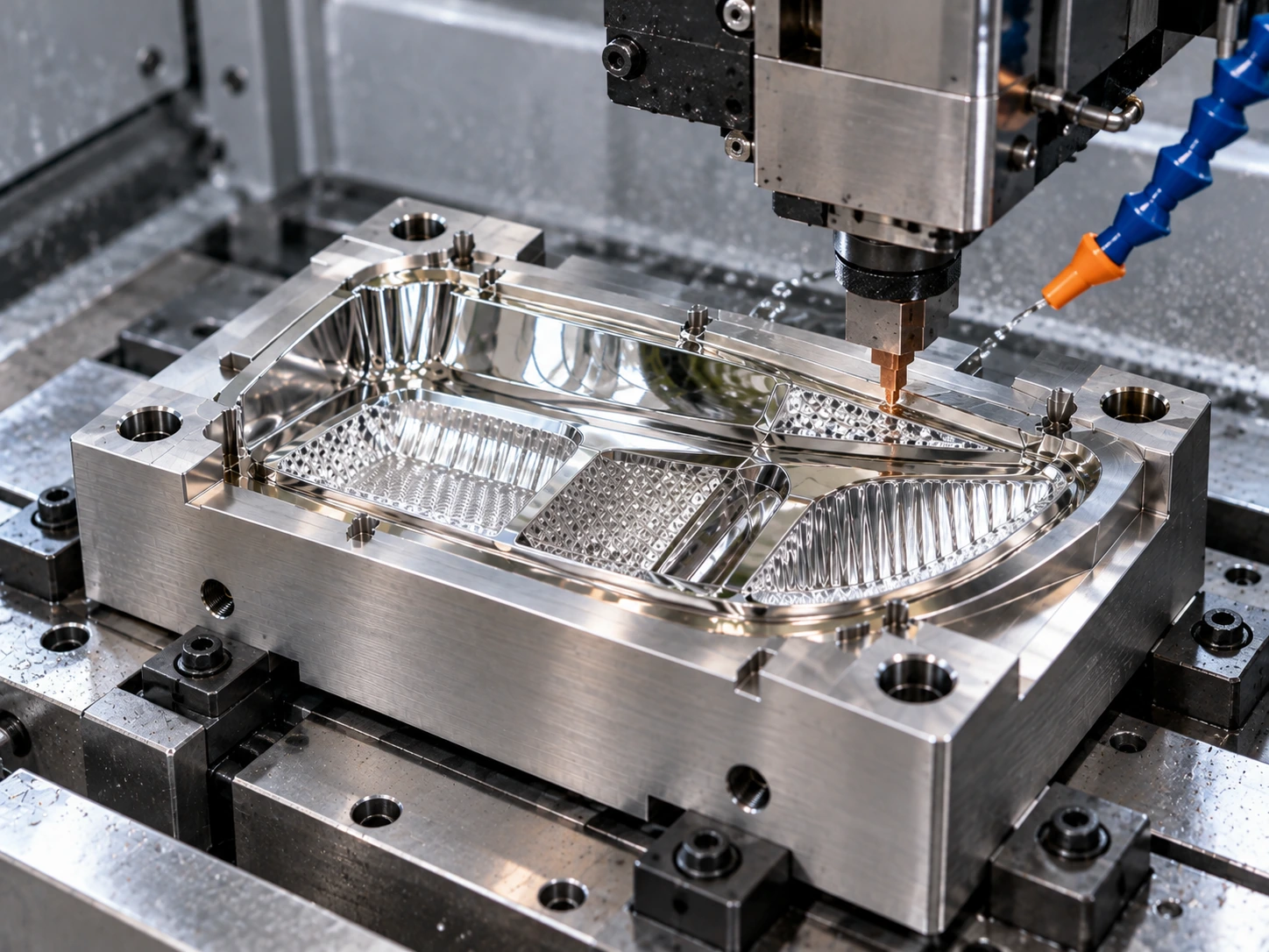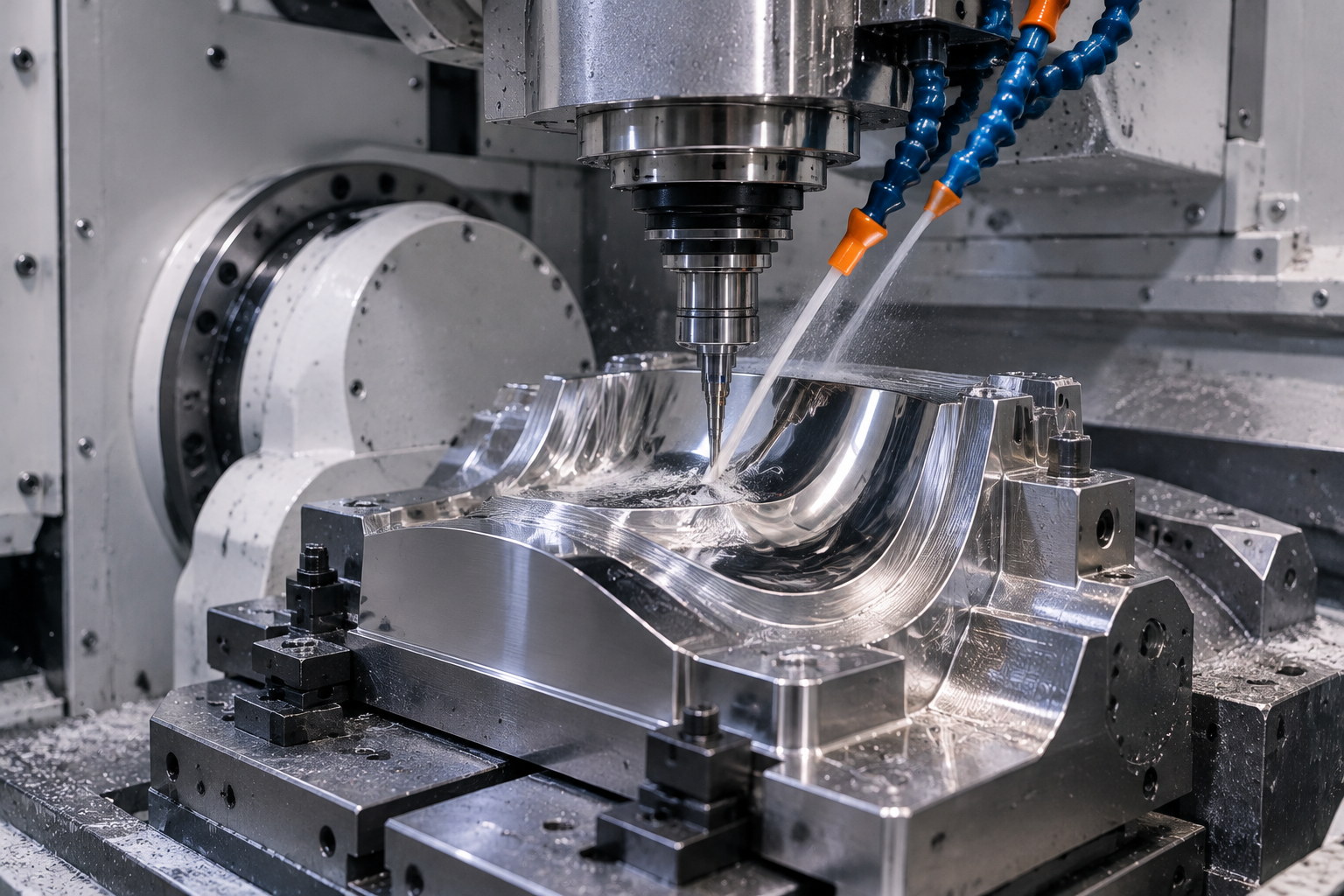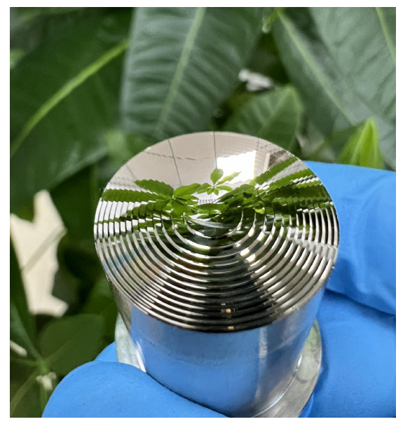
5-axis automated optical polishing delivers consistent surface accuracy on aspheric and freeform surfaces by combining multi-axis kinematic tool orientation, deterministic sub-aperture toolpaths, and closed-loop metrology feedback. Unlike manual or rigid full-aperture polishing, a synchronized 5-axis CNC system continuously aligns the polishing tool perpendicular to the local surface normal of non-rotationally symmetric parts. This continuous normal alignment maintains uniform contact area and predictable dwell times across varying local curvatures, eliminating localized surface form errors (Peak-to-Valley), sub-surface damage, and edge roll-off. For optical engineers and manufacturing buyers sourcing specialized optical polishing services, selecting a provider with automated 5-axis capability is often the deciding factor in transforming high-complexity prototypes into high-yield, repeatable production runs.
This guide examines the kinematic principles of 5-axis automated finishing, contrasts its performance against conventional methods, details key process metrics, outlines material compatibility, and presents an engineering-led evaluation checklist for contract optical manufacturing.
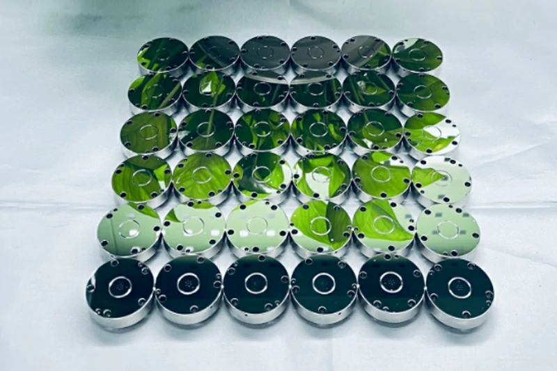
The Complex Surface Dilemma: Why Conventional Optical Polishing Struggles with Aspheric & Freeform Geometries
Optical systems designed for compact assemblies, wide fields of view, and reduced chromatic aberration increasingly rely on aspheric and freeform geometries. However, manufacturing these optics introduces significant polishing challenges:
- Variable Local Curvature: Aspheric lenses feature progressive curvature changes from center to edge, while freeform optics lack any rotational axis of symmetry. Rigid, full-pitch laps cannot conform to these shifting radii without distorting the intended optical profile.
- Edge Roll-Off (Edge Effect): When standard polishing tools cross the physical boundary of an optic, pressure concentrates disproportionately at the periphery, creating severe roll-off that degrades clear aperture utilization.
- Operator Variability: Manual hand correction and semi-automated spindle polishing rely on operator touch to blend high spots. This subjective approach causes wide batch-to-batch variations in Peak-to-Valley (PV) wavefront accuracy.
- Sub-Surface Micro-Fractures: Uncontrolled local pressure spikes from rigid polishing heads frequently induce micro-cracks beneath the surface layer, which later scatter light or cause premature coating failure.
| Polishing Method | Curvature Conformity | Surface Figure Control (PV) | Sub-Surface Integrity | Batch Repeatability |
| Manual / Hand Polishing | Poor across non-spherical zones | Low; highly dependent on operator skill | Inconsistent; prone to local stress points | Low; high scrap rates on complex profiles |
| Full-Aperture Rigid Lapping | Limited strictly to planar or spherical profiles | Moderate on simple radii; fails on freeforms | Uniform on flat stock; creates edge roll-off on curves | Moderate for standard geometries |
| 5-Axis Automated CNC Polishing | Continuous normal-vector tracking | High; deterministic CNC dwell-time control | Controlled; predictable removal rates | High; fully automated recipe execution |
Kinematic Advantage: The Mechanics of 5-Axis Deterministic Polishing
The core operational principle of deterministic optical finishing relies on Preston’s Law, which states that material removal rate ($MRR$) is proportional to the local contact pressure ($P$), the relative velocity between tool and workpiece ($V$), and the processing duration or dwell time ($t$):
$$MRR = C_p \cdot P \cdot V \cdot t$$
Where $C_p$ represents Preston’s empirical coefficient, accounting for slurry chemistry, workpiece material hardness, and polishing pad compliance.
| Process Stage | Kinematic Action | Operational Mechanism | Resulting Quality Benefit |
| Stage 1: Multi-Axis Motion | 5-Axis CNC Synchronized Feeds | Simultaneous translation (X, Y, Z) and tilting (A/B axes) | Enables complete spatial reach across non-symmetrical profiles |
| Stage 2: Vector Alignment | Constant Surface Normal Tracking | Polishing tool vector dynamically aligns perpendicular to local curve | Eliminates contact footprint skewing and local shear spikes |
| Stage 3: Interface Control | Deterministic Footprint Regulation | Compliant pad maintains constant contact zone and uniform force | Stabilizes Prestonian removal parameters ($P \times V$) across the part |
| Stage 4: Dwell-Time Modulation | Variable Traverse Feed Rates | Programmed CNC decelerations on peaks and accelerations over valleys | Eliminates surface high spots without operator guesswork |
| Stage 5: Surface Finalization | Sub-Aperture Deterministic Removal | Controlled material removal following computed toolpath coordinates | Achieves uniform form accuracy and prevents boundary edge roll-off |
On a 3-axis CNC platform, the polishing tool orientation remains static relative to the vertical Z-axis. As the tool traverses a steep aspheric slope or complex freeform saddle, the contact angle shifts, changing the tool contact footprint and causing unpredictable pressure distributions.
A 5-axis automated platform resolves this kinematic limitation through synchronized spatial movement (X, Y, Z translations combined with rotary and tilting axes):
- Continuous Normal Tracking: The machine dynamically adjusts the tilting tool spindle so that the polishing bonnet or pad maintains a constant orientation normal to the local tangent plane of the optic at every point along the toolpath.
- Deterministic Dwell-Time Modulation: Instead of altering tool RPM or applying variable hydraulic downforce, the CNC platform modulates traverse speed. The system dwells longer over surface peaks to remove excess material and moves faster across valleys.
- Sub-Aperture Toolpath Rastering: By utilizing compliant, small-diameter polishing heads (sub-aperture tools) running non-repeating raster, pseudo-random, or spiral paths, the machine mitigates mid-spatial frequency (MSF) spiral marks and prevents regular ripple patterns.
Engineering Benchmarks: Surface Accuracy, Roughness, and Repeatability Control
Achieving consistent results across complex optical components requires simultaneous management of low-frequency form error, mid-frequency ripple, and high-frequency surface roughness.
| Spatial Frequency Domain | Target Metric | Primary Cause of Deviation | Control Mechanism in 5-Axis Polishing |
| Low-Frequency Error | Form Accuracy (PV, RMS Wavefront Error, Astigmatism) | Macro surface mismatch between raw blank and nominal CAD | Iterative dwell-time calculation maps combined with continuous normal-vector orientation |
| Mid-Spatial Frequency (MSF) | Waviness, Tool Grooves, Ripple Patterns | Regular, periodic paths generated by small-diameter polishing tools | Toolpath pseudo-randomization, multi-angle raster passes, and compliant smoothing bonnets |
| High-Frequency Error | Surface Micro-Roughness (Ra, RMS Roughness) | Abrasive particle mechanical shear and pad surface texture | Controlled slurry chemistry, stabilized sub-aperture tool pressure, and micro-abrasive grading |
- Form Accuracy (Peak-to-Valley / PV): Low-frequency spatial errors affect overall wavefront precision and focal collimation. 5-axis automated polishing systematically targets these form errors through corrective dwell-time maps. (Note: Specific achievable tolerances, such as $\lambda/10$ or $\lambda/20$, depend on the specific material, clear aperture dimensions, and initial pre-machined surface quality, and must be verified based on project requirements.)
- Surface Roughness (Ra and RMS): High-frequency micro-roughness directly dictates surface scatter and light transmission efficiency. Compliant tool bonnets paired with precision cerium oxide, diamond, or aluminum oxide slurries reduce micro-roughness down to low-nanometer or sub-nanometer levels without scratching the surface.
- Mid-Spatial Frequency (MSF) Control: Polishing with small tools can inadvertently leave tool marks or “grooves” known as mid-spatial frequency errors, which cause flare or ghost images in imaging optics. Automated 5-axis systems mitigate MSF errors by randomizing tool vector engagements and utilizing multi-directional polishing passes.
- Batch-to-Batch Repeatability: Because all axis feeds, pad dressing schedules, and slurry dispensing rates are controlled via programmed CNC recipes, process drift is minimized across production runs.
Material Adaptability & Core Industrial Applications
Material hardness, fracture toughness, and chemical reactivity determine how an optic responds to mechanical polishing shear stresses. Automated 5-axis polishing systems adapt to diverse substrates by pairing compliant sub-aperture tools with customized slurry chemistries:
- Optical Glasses (e.g., N-BK7, Fused Silica): Fused silica and standard borosilicate crown glasses require tightly managed slurry pH and controlled chemical-mechanical interaction to avoid subsurface micro-fracturing during aggressive aspheric figuring.
- Infrared & Crystalline Materials (e.g., Germanium, Silicon, Zinc Selenide, Calcium Fluoride): Soft or brittle IR materials are prone to cleavage and micro-scratching. 5-axis toolpath control limits shear forces, maintaining surface integrity across steep infrared aspheric lens designs.
- Optical Crystals & Hard Substrates (e.g., Sapphire, Silicon Carbide): High-hardness substrates demand rigid mechanical stability and specialized diamond abrasive slurries, where automated multi-axis engagement ensures steady, gradual material removal.
- Electroless Nickel & Precision Metal Mirrors: Metal freeform mirrors used in reflective optical assemblies benefit from automated polishing to clear diamond-turning diffractive rings without introducing edge roll-off.
Primary Industrial Applications
- Aerospace & Defense: Conformal optical windows and off-axis parabolic mirrors requiring high durability and precise wavefront characteristics under extreme operational conditions.
- Medical Endoscopy & Diagnostic Imaging: Ultra-miniature aspheric lenses designed to minimize spherical aberration in compact camera modules.
- LiDAR & Autonomous Sensing: Asymmetric freeform lenses that optimize laser signal collection while fitting into non-standard mechanical envelopes.
- Industrial Laser Processing: Beam-shaping optics engineered to withstand high laser damage thresholds (LIDT) through the elimination of subsurface defects.
The Metrology Loop: In-Process Measurement and Closed-Loop Correction
A 5-axis CNC polishing machine is only as effective as the metrology data driving its toolpath algorithms. High-precision manufacturing relies on an iterative, closed-loop metrology process rather than open-loop estimation:
| Loop Phase | Process Action | Tools & Methods Involved | Critical Output |
| Phase 1: Surface Acquisition | Topography Mapping | Non-contact optical profilometry, CGH, or stitching interferometry | High-resolution 3D point cloud of actual surface shape |
| Phase 2: Error Computation | Deviation Matrix Generation | CAM analysis comparing measured profile to native CAD / sag formula | Discrete spatial height error map indicating positive peaks |
| Phase 3: Path Synthesis | 5-Axis Dwell Programming | Algorithmic post-processing of vector velocities and spindle orientations | Corrective CNC machine code with modulated feed rates |
| Phase 4: CNC Polishing | Deterministic Execution | Automated 5-axis motion with controlled slurry distribution | Localized material removal targeting identified surface high spots |
| Phase 5: Final Verification | Tolerance Gate Check | Secondary interferometric inspection against engineering drawings | Pass: release to packaging / Fail: secondary corrective loop |
- Surface Topography Acquisition: The optic is measured using non-contact optical profilometry, computer-generated hologram (CGH) interferometry, or stitching interferometry to produce a high-resolution height error map.
- Error Matrix Computation: Software compares the measured surface against the nominal design model (such as a native STEP model, Zernike polynomial equation, or sag table) to calculate the precise spatial distribution of excess material.
- Corrective Toolpath Generation: The CAM post-processor translates this error map into dynamic 5-axis machine code, setting longer dwell times over positive deviations while maintaining normal surface orientation.
- Iterative Verification: The process repeats in fine-finishing cycles until the optical component converges within specified form and roughness design thresholds.
For complex projects requiring tight surface accuracy tolerances, partnering with an experienced optical manufacturing specialist that integrates advanced precision optical polishing and lapping services ensures this closed-loop feedback cycle is properly executed from raw blank to final inspection.
Buyer’s Decision Framework: Sourcing Precision Optical Polishing Services
When outsourcing aspheric and freeform optical polishing, technical buyers and optical engineers must look beyond basic machine listings. Use the following engineering checklist to verify whether a supplier has true 5-axis automated finishing capabilities:
- Kinematic Machine Configuration:
- Confirmation: Does the facility operate true 5-axis continuous path CNC polishing machines, or do they rely on 3-axis equipment with manual part repositioning?
- Impact: 3-axis setups cannot maintain constant tool-normal alignment over steep curves, resulting in non-uniform surface roughness and uneven material removal.
- Metrology and Surface Data Handling:
- Confirmation: Can the supplier directly import native CAD files, sag formulas, or point clouds into their machine CAM software to generate corrective dwell-time maps?
- Impact: Incompatible metrology workflows prevent closed-loop iterative correction, capping surface accuracy.
- Sub-Surface Damage (SSD) Mitigation:
- Confirmation: What specific slurry grading, pad conditioning, and intermediate lapping steps are deployed prior to final optical polishing?
- Impact: Skipping intermediate deterministic polishing stages leaves subsurface cracks that compromise laser damage thresholds (LIDT) and optical coatings.
- Toolpath Randomization & MSF Suppression:
- Confirmation: Does the supplier’s CAM software incorporate path-randomization algorithms to prevent regular tool ripples (mid-spatial frequency errors)?
- Impact: Unchecked MSF errors introduce stray light, flare, and halo artifacts in high-resolution imaging applications.
- Process Documentation and Quality Verification:
- Confirmation: Does the supplier provide complete interferometric inspection reports, surface roughness profiles, and batch repeatability data with delivered parts? (Note: Specific inspection protocols, calibration standards, and reporting formats should be established directly with the manufacturing partner prior to production).
Key Takeaways
- Root Cause of Inconsistency: Conventional full-aperture and manual polishing fail on aspheric and freeform optics because shifting local curvatures prevent constant contact area and uniform pressure distribution.
- 5-Axis Kinematic Solution: Synchronized 5-axis CNC motion maintains the polishing tool perpendicular to the local surface normal at all times, ensuring predictable removal rates based on Preston’s Law.
- Deterministic Dwell-Time Control: Automated polishing corrects form errors by varying the tool’s dwell time over high zones rather than relying on inconsistent manual intervention.
- Closed-Loop Metrology: High-precision surface finishing requires an iterative cycle of non-contact interferometric or profilometric measurement, automated dwell-time compensation, and secondary corrective passes.
- Supplier Vetting Criteria: Sourcing successful optical components requires verifying that the manufacturing partner utilizes native CAD-driven CAM post-processors, active MSF suppression toolpaths, and verified metrology reporting.
Frequently Asked Questions (FAQ)
What is the primary difference between 5-axis automated polishing and Magnetorheological Finishing (MRF)?
5-axis automated polishing uses compliant mechanical pads or bonnets combined with abrasive slurries to finish complex optics through multi-axis kinematics. Magnetorheological Finishing (MRF) uses a magnetically stiffened ribbon of fluid that acts as a sub-aperture polishing tool. While MRF is highly deterministic for final figure correction, 5-axis CNC polishing offers broader material removal rates, handles larger pre-polish surface deviations, and is widely utilized for primary shaping, smoothing, and corrective finishing.
Can 5-axis optical polishing eliminate mid-spatial frequency (MSF) errors on freeform optics?
Yes, when combined with optimized sub-aperture toolpaths. If a small polishing tool moves in rigid, repetitive raster passes, it can induce periodic micro-grooves (mid-spatial frequency ripple). Advanced 5-axis CAM systems eliminate this effect by implementing pseudo-random toolpaths, variable-angle rastering, and compliant smoothing bonnets that blend tool footprints across the clear aperture.
What technical data must buyers provide to evaluate an aspheric or freeform polishing project?
To accurately assess toolpath feasibility and cycle times, optical manufacturers require:
- Complete 2D engineering drawings indicating clear aperture, mechanical dimensions, and surface tolerances (e.g., PV, RMS, Ra, and scratch-dig specifications).
- 3D CAD models (STEP/IGES) or exact mathematical surface definitions (such as Zernike polynomial coefficients, aspheric sag formulas, or point cloud files).
- Substrate material specifications, including glass type, crystal orientation, or thermal restrictions.