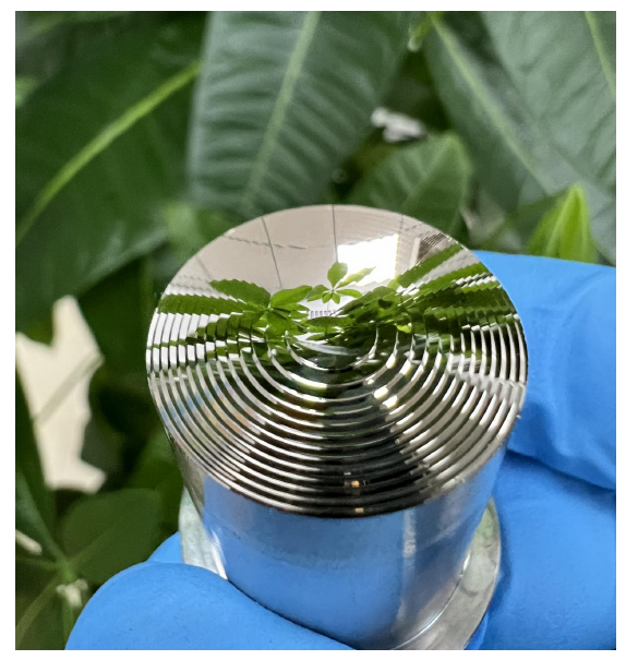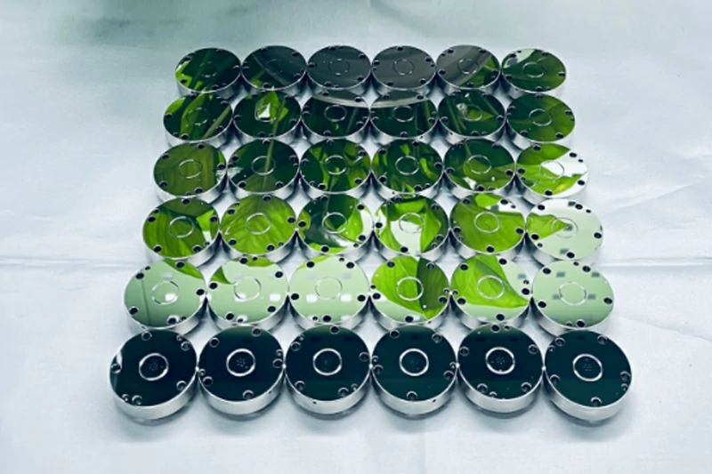
Achieving a high-precision surface finish requires balancing mechanical shear, chemical removal rates, and contact stress distribution. In precision optical mirror polishing, components frequently pass visual checks under standard illumination yet fail metrological inspection under laser interferometry or white light interferometry. The primary drivers behind rejected optics are three recurring surface finish anomalies: orange peel, mid-spatial frequency waviness, and edge roll-off.
Resolving these fabrication defects demands identifying whether an issue stems from chemical slurry agglomeration, kinematic tool path resonance, or viscoelastic lap compression at the component boundary. This guide examines the mechanical root causes of these three optical surface finishing failures and presents practical machine parameter adjustments, tooling corrections, and process limits for precision optical manufacturing.
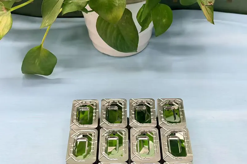
Beyond Specular Reflection: Why Optical Mirror-Polishing Failures Occur
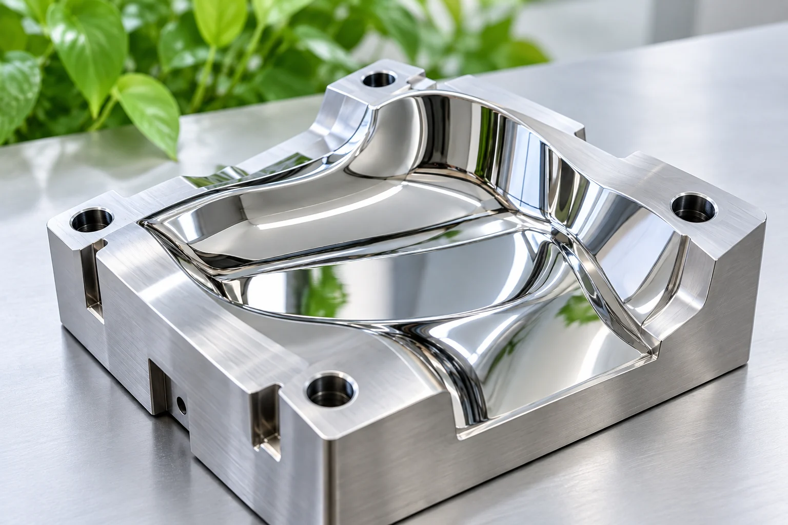
A specular, reflective surface does not guarantee optical performance. While cosmetic mirror polishing focuses on high-frequency roughness ($Ra$) to eliminate visible scatter, optical-grade surfaces must satisfy functional wavefront specifications across high-, mid-, and low-spatial frequency domains.
When process variables fluctuate, specific surface errors develop:
- High-spatial frequency errors (Roughness & Orange Peel): Cause wide-angle scatter, stray light, and transmission loss.
- Mid-spatial frequency errors (Waviness & Ripple): Cause small-angle scatter, halo effects around focused spots, and direct reduction of system Modulation Transfer Function (MTF).
- Low-spatial frequency & boundary errors (Form Error & Edge Roll-Off): Introduce spherical aberration, reduce the functional clear aperture, and distort beam collimation.
The table below contrasts the mechanical signatures and metrology profiles of the three core polishing defects:
| Defect Mode | Spatial Frequency Regime | Typical Metrology Tool | Primary Functional Risk |
| Orange Peel | High-spatial frequency ($>0.5\text{ mm}^{-1}$) | White light interferometer, Optical profiler | Stray light generation, laser-induced damage threshold (LIDT) reduction |
| Surface Waviness | Mid-spatial frequency ($0.05\text{ mm}^{-1} – 0.5\text{ mm}^{-1}$) | Fizeau phase-shifting interferometer | Contrast loss, MTF degradation, image ghosting |
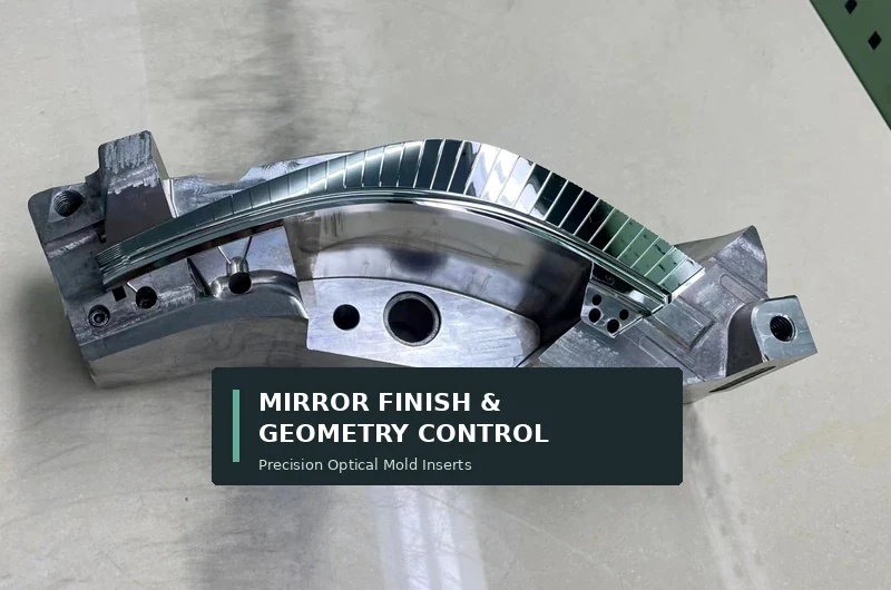
| Edge Roll-Off | Low-spatial boundary defect ($<0.05\text{ mm}^{-1}$) | Deflectometry, Contact/optical profilometry | Reduction of clear aperture, aperture edge clipping, peripheral wavefront deformation |
Defect #1: Orange Peel — Root Causes, Subsurface Mechanisms, and Corrective Action
Orange peel presents as a dimpled, mottled topography resembling the skin of an orange. It reflects localized micro-roughness variations that degrade optical clarity and scatter high-energy laser beams.
Micro-Mechanisms Behind Orange Peel Formation
Orange peel rarely originates from machine kinematics. Instead, it is governed by chemical-mechanical imbalances and material structure:
- Slurry Particle Agglomeration: When abrasive particles in cerium oxide, diamond, or colloidal silica slurries aggregate into dense clusters, they act as oversized cutting tools. Instead of ductile-regime polishing, these clusters cause localized micro-fracture and uneven material removal.
- Subsurface Grain Anisotropy: In poly-crystalline optical substrates, copper, or aluminum mirrors, differing crystallographic grain orientations exhibit varying removal rates. Polishing for extended durations selectively etches softer grains faster than harder ones.
- Over-Polishing: Continuing a polishing cycle past the point where initial subsurface micro-cracks have been removed induces mechanical flow on the surface, pulling grains out and exacerbating micro-cavities.
Practical Workshop Fixes: Slurry Chemistry, Pad Hardness, and Cycle Timing
To eliminate orange peel without stripping dimensional accuracy, implement the following workshop corrections:
- Control Slurry Conditioning and pH: Maintain rigorous filtration loops (1–5 micron cartridge filters depending on grain size) and monitor slurry suspension chemistry. Prevent pH shifts in alkaline colloidal silica to avoid spontaneous particle agglomeration.
- Transition to Harder Lap Interfaces: Soft, compliant pads (such as napped synthetic felts) conform into micro-cavities, accelerating preferential grain erosion. Switch to rigid synthetic polyurethane pads or formulated pitch laps that bridge grain boundaries rather than sinking into them.
- Truncate Polishing Time Windows: Establish baseline removal cycles using pre-polishing metrology. Once the damage layer from fine grinding is removed, stop the cycle immediately to prevent ductile-layer degradation.
Where shop-floor setups cannot stabilize slurry dispersion or pad rheology during critical runs, opting for high-stability precision optical polishing and lapping services ensures controlled thermal environments and continuous slurry management required for sub-nanometer roughness.
Defect #2: Surface Waviness — Managing Mid-Spatial Frequency (MSF) Errors
Surface waviness—often termed “ripple” or “mid-spatial frequency (MSF) error”—consists of quasi-periodic surface height variations across lateral scales from fractions of a millimeter up to several centimeters.
Kinematics and Tool Path Resonance: Where MSF Artifacts Originate
Unlike random high-frequency micro-roughness, waviness directly mirrors machine dynamics and tool interaction:
- Deterministic Tool Overlap: Sub-aperture computer-controlled polishing (CCOP) or single-point diamond turning (SPDT) leaves discrete step patterns when tool path step-over intervals are too wide or poorly randomized.
- Mechanical Vibration & Runout: Spindle unbalance, drive belt harmonics, and worn axis bearings print cyclical mechanical pulses directly onto the optical face as the lap traverses the part.
- Velocity Mismatch in Planetary Motion: On continuous planetary polishing machines, incorrect gear ratios between the sun gear, internal ring gear, and carrier nests lead to repetitive epicyclic trajectories, concentrating tool sweeps over identical annular tracks.
Process Optimization to Suppress Tool Marks and Ripple Patterns
Suppression of mid-spatial waviness depends on kinematic de-synchronization and compliance control:
- Pseudo-Random Tool Paths: For CNC sub-aperture polishing heads, replace raster or simple spiral tool paths with pseudo-randomized cycloidal paths (such as Lissajous or continuous random-walk vectors). This breaks cyclical overlap signatures.
- Optimize Spindle Speed Ratios: On planetary laps, adjust top-plate, bottom-plate, and carrier rotational velocity ratios so the track repeat period exceeds the total cycle time. Never polish at integer rotational ratios.
- Tuning Pad-to-Part Spatial Compliance: Match lap stiffness to the target spatial frequency band. If tool marks exist at a 2 mm period, a tool with a 15–20 mm contact footprint coupled with an elastomer damping layer will bridge the ripple peaks and shear them down without following the valleys.
Defect #3: Edge Roll-Off — Eliminating Periphery Curvature and Preserving Clear Aperture
Edge roll-off (rolled edge) occurs when the peripheral perimeter of a flat or spherical optical substrate exhibits an accelerated rate of material removal, creating an uncorrectable downward curvature along the boundary.
The Mechanics of Edge Compression and Over-Hang Pressure Spikes
Edge roll-off is driven by viscoelastic lap mechanics governed by the Preston equation ($R = k \cdot P \cdot V$):
- Prestonian Pressure Concentration: When an optical substrate moves across a compliant polishing pad, the leading and trailing edges push into the pad material. The pad compresses, concentrating dynamic local pressure ($P$) along the outer 1–5 mm rim of the substrate. Because removal rate correlates with pressure, the edge erodes significantly faster than the center.
- Tool Overhang: In stroke-based polishing, allowing the polishing tool or part to overhang the edge of the mating plate causes an immediate boundary pressure peak followed by edge rounding.
Fixturing and Lapping Strategies to Maintain Boundary Flatness
Maintaining uniform edge profile flatness requires physical pressure management:
- Use Sacrificial Retaining Rings (Blocking Rings): Mount identical-material guard rings or scrap optical blanks around the active workpiece. The polishing pad encounters a continuous flat plane, moving the mechanical pressure spike to the disposable border and shielding the critical clear aperture.
- Transition from Synthetic Pads to Pitch Laps: Synthetic pads feature high vertical compliance that wraps around component boundaries. Optical pitch exhibits visco-plastic behavior: it resists rapid edge compression while flowing under steady pressure, drastically reducing edge dip.
- Refine Edge Bevel Geometry: Ensure protective edge chamfers or bevels are ground at 45° with a clean, chip-free transition prior to polishing. A ragged pre-bevel disrupts slurry hydrodynamic wedge formation, inducing localized turbulence and boundary degradation.
For high-aspect-ratio optical flats requiring edge-to-edge flatness down to the final millimeter, shifting from single-side manual pads to balanced double-sided lapping and polishing balances top-and-bottom hydrodynamic pressures, neutralizing boundary curvature.
Quick Reference Matrix: Polishing Defects, Root Causes, and Corrective Actions
Use this troubleshooting matrix to identify and correct mirror polishing defects on the shop floor:
| Polishing Defect | Primary Surface Signature | Mechanical & Chemical Root Cause | Immediate Parameter Tuning | Long-Term Process Correction |
| Orange Peel | Dimpled, hazy surface; elevated high-frequency RMS roughness ($Rq$) | Abrasive agglomeration; differential grain removal; excessive cycle time | Reduce slurry concentration; lower applied head pressure; shorten polishing run | Implement sub-micron slurry filtration; switch to harder polyurethane or pitch lap |
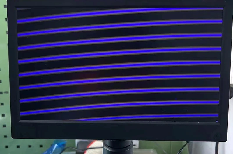
| Surface Waviness | Annular rings, periodic ripples; distorted interferogram fringes | Deterministic tool overlap; drive-line harmonic vibration; integer planetary speed ratios | De-synchronize carrier and plate rotational speeds; damp mechanical vibrations | Implement pseudo-randomized tool paths; introduce compliant backing dampeners |
| Edge Roll-Off | Sharp downward fringe bending at perimeter; loss of outer clear aperture | Viscoelastic pad deformation; edge pressure concentration; lap overhang | Reduce tool stroke length to eliminate overhang; decrease downward pneumatic pressure | Apply sacrificial blocking rings; convert process to optical pitch or double-sided planetary lapping |
Transitioning from In-House Rework to Specialized Subcontracting: When to Outsource
Minor surface variations can often be resolved with on-machine process adjustments. However, certain technical thresholds and commercial constraints make internal rework impractical or cost-prohibitive:
- Severe Clear Aperture Specifications: When drawings mandate usable aperture exceeding 95% to 98% of the physical diameter, standard single-sided polishing tooling cannot prevent roll-off without complex blocking fixtures.
- Strict Wavefront & MSF Limits: High-performance imaging, semiconductor inspection, and high-energy laser mirrors often specify transmitted or reflected wavefront distortion below $\lambda/10$ Peak-to-Valley alongside mid-spatial PSD (Power Spectral Density) ceilings. Reaching these tolerances requires continuous-run planetary double-sided machines and cleanroom-grade slurry conditioning.
- Metrology Verification Gaps: Diagnosing subtle orange peel or mid-spatial ripple requires phase-shifting interferometers, absolute-calibrated transmission flats, and optical profilometers. Without in-house optical metrology, polishing adjustments become guesswork.
Utilizing dedicated contract optical polishing and lapping solutions gives manufacturers direct access to production-scale planetary equipment, calibrated interferometric testing, and deterministic process controls that stabilize yield on complex optical substrates.
Key Takeaways
- Defects occur in distinct frequency domains: Orange peel is a high-frequency chemical-mechanical surface breakdown; waviness is a mid-spatial kinematic resonance issue; edge roll-off is an edge boundary contact-pressure problem.
- Orange peel is driven by chemistry and over-polishing: Agglomerated abrasives and extended run cycles selectively erode softer material matrices. Address it by filtering slurries, using firmer laps, and limiting cycle duration.
- Kinematics cause waviness: Never run deterministic, repeating paths at integer gear ratios. Randomize sub-aperture sweep vectors and decouple drive-line vibrations to keep mid-spatial frequencies in check.
- Pad compliance drives edge roll-off: Soft synthetic pads compress and curl around component perimeters under Prestonian pressure spikes. Counter this by implementing sacrificial boundary rings or rigid pitch tooling.
- Know the limits of single-sided manual reworking: When boundary tolerances, clear aperture ratios ($>95\%$), and total wavefront error requirements exceed standard tool setups, switching to double-sided planetary production prevents cycle scrap.
Frequently Asked Questions About Optical Mirror Polishing Defects
Can surface waviness be polished out without altering optical flat figure?
Yes, provided the polishing lap matches the spatial wavelength of the waviness. To eliminate waviness without disrupting overall form figure (power and irregularity), technicians must utilize a semi-rigid lap that bridges the ripple peaks while floating across overall curvature. Applying very soft pads will conform to the ripples, while an excessively stiff, flat tool can introduce global spherical curvature.
How does slurry pH and temperature affect the occurrence of orange peel?
Chemical-mechanical polishing (CMP) slurries rely on tight zeta potential windows to keep particles suspended and prevent clumping. If slurry pH shifts toward the isoelectric point, abrasive particles rapidly agglomerate into micron-scale clusters that gouge and dimple the surface. Uncontrolled slurry temperature exacerbates this by altering chemical hydration rates and local surface hardness, producing localized orange peel texture.
What is the ideal bevel angle to minimize edge roll-off in mirror optics?
A uniform 45-degree protective bevel (chamfer) with a nominal width of 0.2 mm to 0.5 mm (depending on component diameter) is standard. Critically, the bevel transition must be finely ground or pre-polished. Sharp, jagged 90-degree transitions cause hydrodynamic boundary layers to collapse, driving the polishing pad into the rim and accelerating roll-off.
How do pitch laps compare to synthetic polyurethane pads in preventing edge roll-off?
Optical pitch laps are far superior to synthetic polyurethane pads for edge preservation. Polyurethane pads contain foam-like cellular structures that compress elastically under vertical load and wrap around workpiece edges. Optical pitch acts as a high-viscosity, non-Newtonian fluid: it holds rigid dimensional shear under high-speed motion, suppressing edge compliance and keeping fringe lines straight to the perimeter.