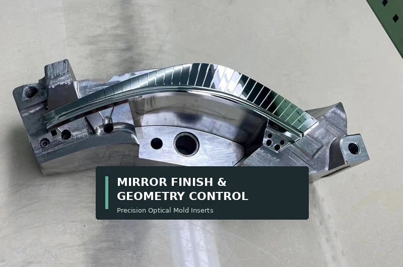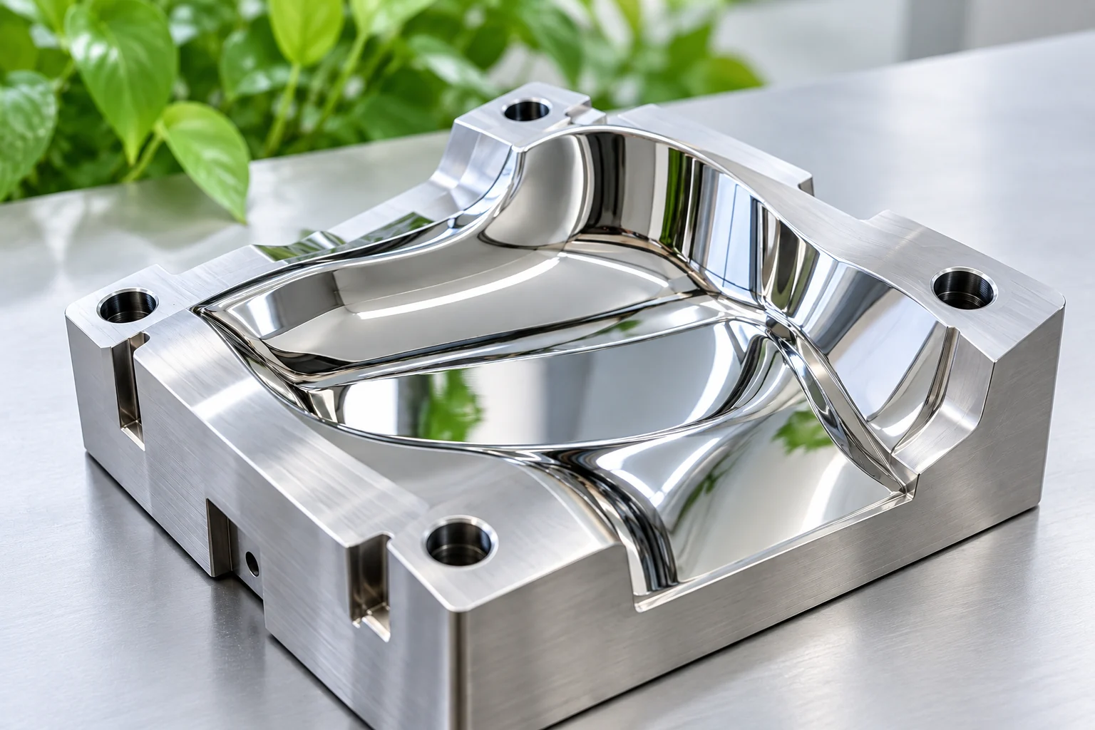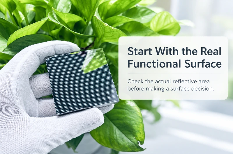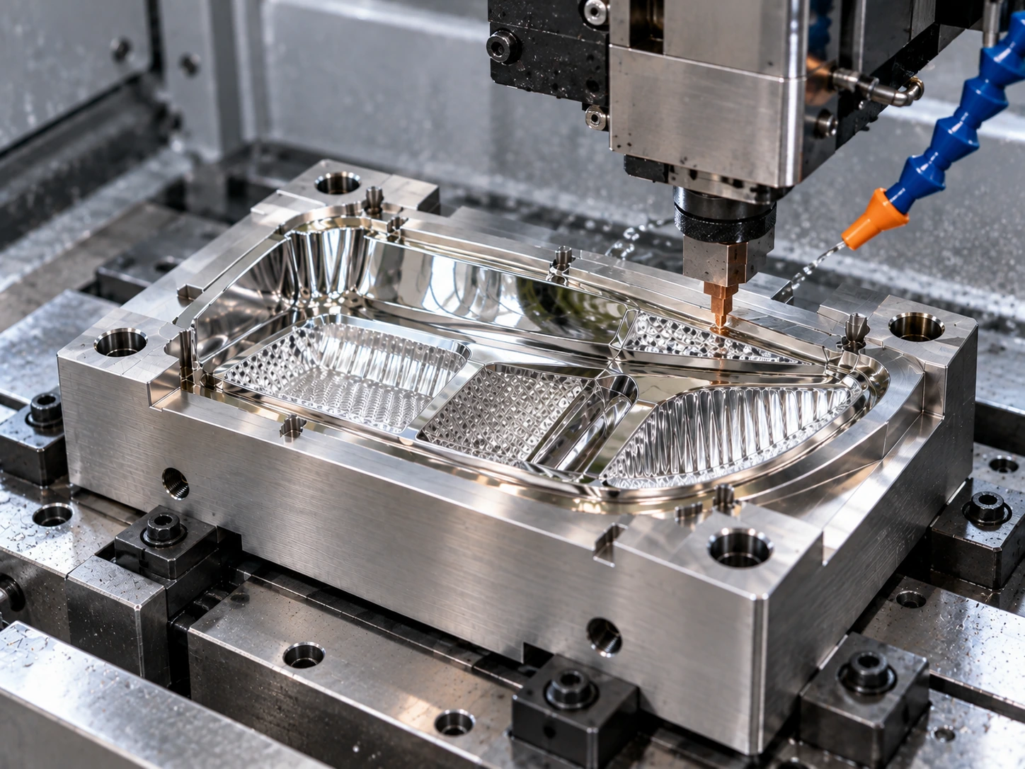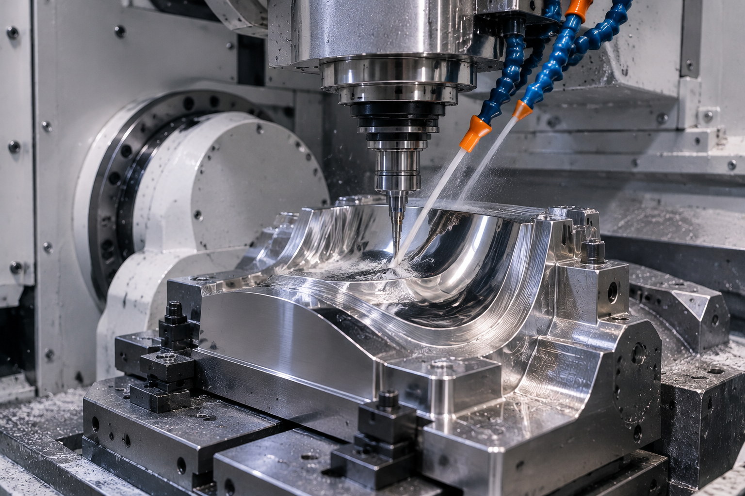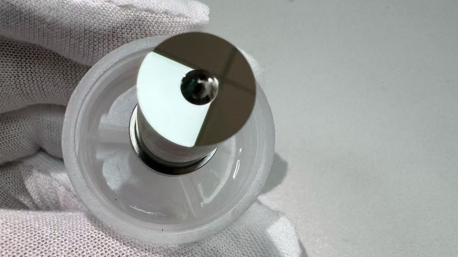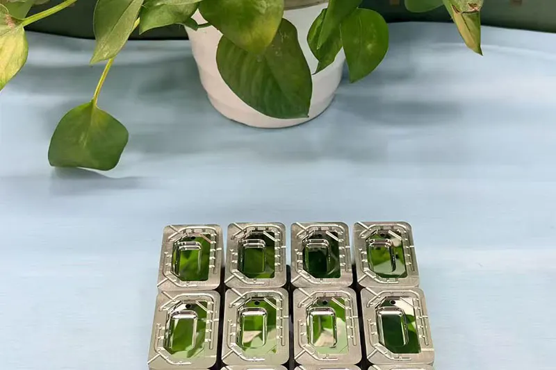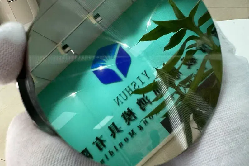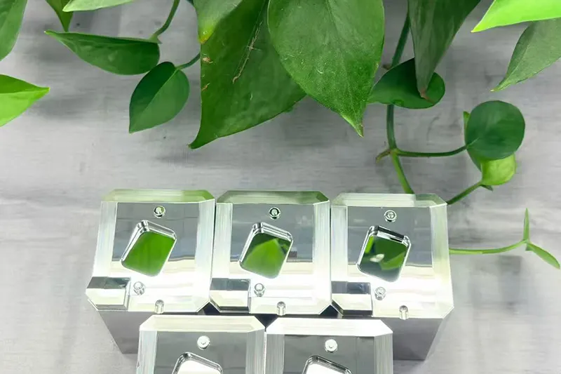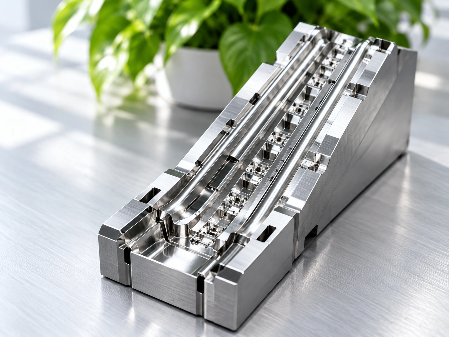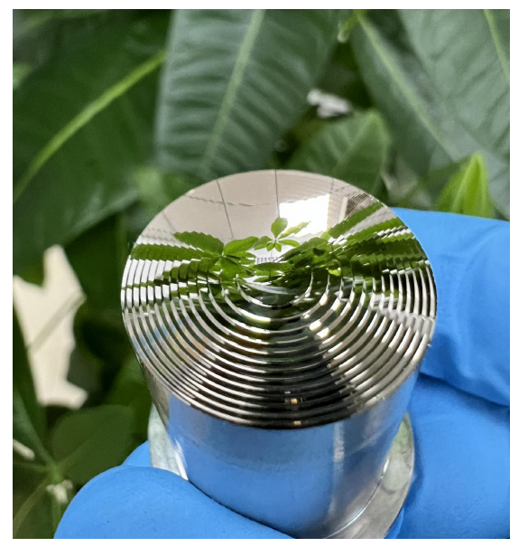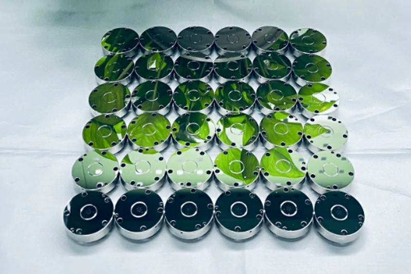
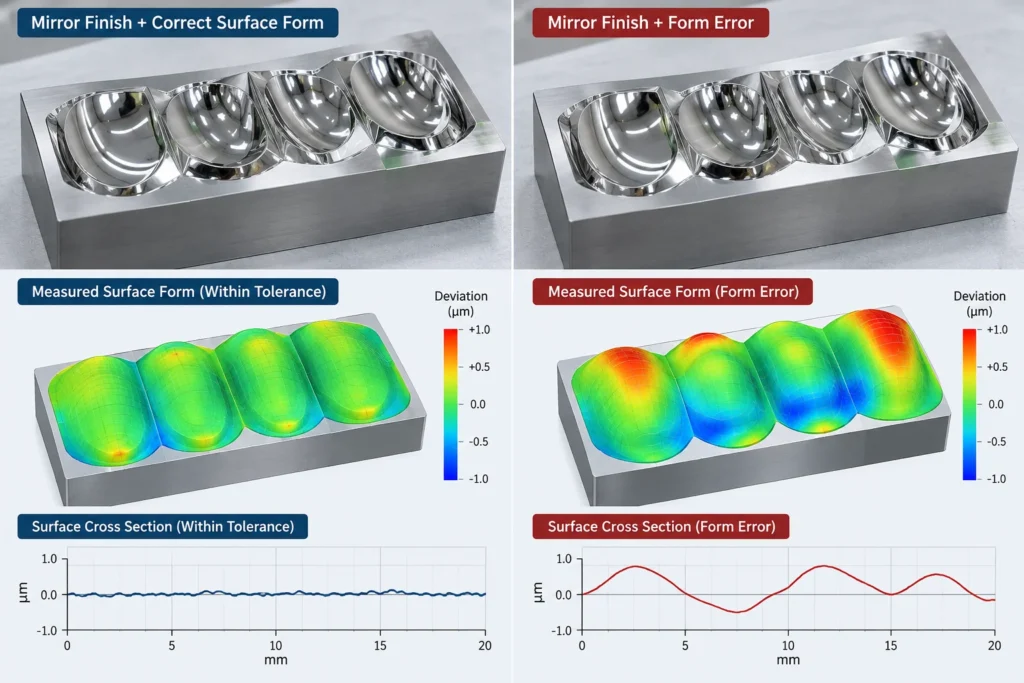
The surface looks beautiful. It is bright, smooth, and almost completely free of visible tool marks.
But when the customer checks the finished mold insert against the original 3D model, the surface is no longer exactly where it should be.
Some areas have lost their intended curvature. Others show small form deviations near transitions. In optical applications, the reflected image or light distribution may no longer behave as expected.
For customers ordering freeform optical mold inserts, this is a serious problem. They are not simply buying a polished metal surface. They need a specific three-dimensional geometry that must remain accurate through machining, finishing, and final inspection.
At YISHUN Optical, we believe the most important part of freeform mold insert machining is not making the surface look brighter. It is preserving the geometry that makes the surface functional.
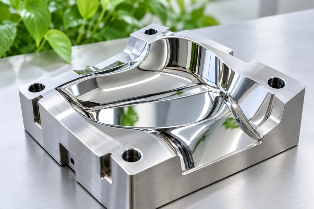
A Mirror Finish Cannot Prove Surface Accuracy
One of the most common misunderstandings in precision machining is treating surface roughness and surface form as the same requirement.
They are different.
Surface roughness describes small-scale irregularities on the finished surface. Surface form describes how closely that surface follows its intended three-dimensional shape.
A mold insert can have extremely low roughness and still contain form errors.
For example, a freeform reflector insert may look smooth under ordinary workshop lighting. However, a small change in local curvature can affect the direction of reflected light.
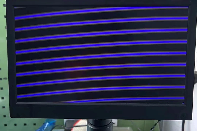
A cosmetic freeform surface can show distorted reflection lines even when no obvious scratches are visible.
This matters in automotive optical systems, AR-HUD components, precision lenses, and appearance-sensitive products.
If the design depends on a carefully calculated surface, reducing roughness alone is not enough.
The finished geometry must also remain within the specified form tolerance.
Why Freeform Surfaces Are More Difficult to Control
A conventional flat surface is relatively straightforward to reference and inspect.
A freeform surface is different.
Its curvature changes across the component, sometimes in several directions at once. The local surface normal and cutting conditions may change continuously during machining.
This introduces challenges that are not always visible in the drawing.
The cutting tool must follow the correct path while maintaining suitable contact conditions. At the same time, the machine must control axis movement, tool deflection, and thermal stability.
On a complex optical mold insert, some areas may be easily accessible while others have steep slopes or restricted transitions.
A machining strategy that works well in one region may produce different surface quality or geometric accuracy elsewhere.
Temperature changes can also affect dimensional stability during demanding precision work. We discuss this issue in more detail in our guide to temperature control in ultra-precision machining.
For this reason, we do not evaluate a freeform mold insert only by its overall size or the roughness value shown on the drawing.
We review the actual surface geometry and identify the areas where machining or finishing could change the intended form.
Surface Accuracy Should Be Established During Machining
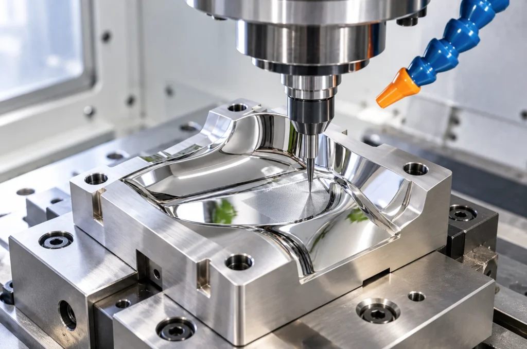
A common mistake is leaving too much responsibility to the final polishing stage.
If the original machined surface contains significant form error, polishing cannot automatically correct it.
In fact, unrestricted material removal can make the geometry worse.
For suitable freeform structures, our preferred approach is to establish the required geometry as accurately as practical during precision machining.
This may involve five-axis machining or an appropriate ultra-precision process, depending on the material and surface requirements.
Through precision CNC machining, we can evaluate cutting strategies that consider surface curvature, tool accessibility, machining stability, and the dimensional requirements of complex mold inserts.
The tool path must account for local curvature, accessible cutting directions, tool contact conditions, and transitions between adjacent regions.
We also consider whether changing the tool orientation can improve cutting stability and reduce unnecessary tool extension.
The objective is to create a controlled starting surface before any additional finishing work begins.
A better starting surface reduces the amount of material that must be removed later.
It also makes the finishing process easier to evaluate and control.
Polishing Can Improve Roughness While Damaging the Designed Shape
Freeform surfaces are particularly sensitive to uneven polishing.
Unlike a simple flat surface, the local curvature changes across the workpiece. Polishing contact, pressure, dwell time, and accessibility may vary from one region to another.
If the finishing process is not carefully controlled, some areas may lose more material than others.
The surface may become smoother while the original form gradually changes.
This is especially dangerous near steep transitions, edges, narrow curved features, and functional optical regions.
A small amount of unintended material removal may alter the local slope.
For optical components, slope errors can influence reflected or transmitted light even when the surface remains visually smooth.
At YISHUN Optical, we approach finishing as a controlled process rather than an open-ended effort to achieve the brightest possible surface.
One way to reduce this risk is to improve the machined surface before polishing begins. Our article on high-gloss mold insert machining with less hand polishing explains why a better starting surface can reduce unnecessary finishing work.
We first consider which areas actually require additional work.
We then evaluate the surface condition, remaining allowance, geometry sensitivity, and suitable finishing method.
The key is to avoid correcting a cosmetic issue by introducing a geometric one.

Protecting Critical Regions Instead of Polishing Everything Equally
Not every part of a freeform mold insert has the same functional importance.
Some regions control optical performance. Others are transition surfaces, supporting areas, or noncritical geometry.
Treating every region with the same finishing pressure and removal strategy can create unnecessary risks.
We prefer to identify critical surfaces before machining and finishing.
For example, an optical freeform insert may contain a central functional surface, a steep transition area, and surrounding positioning features.
The central surface may require controlled roughness and form accuracy.
The transition area may require particular attention to edge geometry and local curvature.
The positioning features may need dimensional stability without additional mirror polishing.
Small radii and sharp transitions deserve particular attention because polishing can unintentionally change their geometry. We explain this risk further in our article on small-radius mold insert machining.
Separating these requirements helps prevent unnecessary surface treatment.
It also improves communication between the customer, machining team, finishing operators, and inspection personnel.
The goal is not to apply the most intensive finishing process everywhere.
It is to apply the correct process to the correct area.
Inspection Must Compare the Finished Surface With the Design
Visual appearance can reveal scratches, tool marks, and obvious reflection defects.
However, it cannot prove that a freeform surface matches its original CAD geometry.
For precision freeform mold inserts, inspection must be planned around the customer’s functional requirements.
Dimensional measurement may be needed to verify the relationship between the freeform surface and the component’s reference datums.
Surface-form inspection may require suitable coordinate or optical measurement techniques, depending on accessibility, slope, size, material, and required accuracy.
Surface roughness may require a separate measurement method.
At YISHUN Optical, our inspection resources include precision coordinate measurement and optical surface measurement equipment.
However, not every method is suitable for every freeform geometry.
Steep slopes, restricted areas, surface reflectivity, and measurement range can limit what a particular instrument can verify.
We therefore discuss the inspection strategy during technical review rather than waiting until machining is complete.
For demanding applications, customers should define the required form tolerance, evaluation area, measurement datum, and acceptance method before production begins.
This reduces the risk of producing a visually attractive component that cannot be accepted under the intended inspection conditions.
When a Freeform Insert Needs More Than One Process
Some freeform mold inserts combine smooth optical surfaces with small radii, steep walls, or complex surrounding structures.
A single machining method may not be suitable for every feature.
For example, one region may be accessible through precision milling, while a restricted corner requires a different machining approach.
Material selection also matters. A process suitable for a diamond-machinable material may not be appropriate for hardened tool steel.
At YISHUN Optical, we review the component as a complete structure before selecting the processing route.
Our capabilities include five-axis precision machining, ultra-precision machining, controlled mirror finishing, and complementary processes for difficult features.
For optical applications involving steep surface slopes, narrow transitions, and challenging geometries, our AR/VR optical mold insert machining capabilities provide additional context on how machining access, surface form, and inspection requirements must be considered together.
The final route depends on geometry, material, tolerances, accessibility, and inspection requirements.
Using multiple processes can be appropriate, but every additional setup or finishing operation introduces potential risks.
Datum relationships, material removal, and transitions between processes must therefore be considered carefully.
The objective is not to use more processes.
It is to use the necessary processes while protecting the required surface geometry.
How We Review Freeform Mold Insert Projects
When a customer sends us a freeform mold insert project, we first examine the 3D model rather than focusing only on the requested mirror finish.
We identify the functional surfaces and any regions where changes in curvature could affect performance.
We then review the material, critical dimensions, form tolerance, local surface slopes, minimum radii, and available machining access.
Next, we consider which machining approach can establish the required geometry with the least unnecessary finishing.
If additional polishing is required, we evaluate the risk of changing the surface form.
Finally, we review how the finished insert will be inspected.
This process helps us identify potential conflicts between surface quality, geometry, machining accessibility, and measurement capability before production begins.
Not every project can be accepted with the same machining or inspection assumptions. Difficult surfaces may require additional engineering evaluation or discussion of practical acceptance boundaries.
The Real Goal Is a Mirror Surface That Still Matches the Design
A freeform mold insert is successful only when its finished condition meets the requirements that matter to the customer.
A bright surface may be desirable, but accurate geometry is essential when that geometry determines optical function or appearance.
The machining process must establish the intended form.
Finishing must improve the surface without unnecessarily changing that form.
Inspection must verify the agreed characteristics using suitable methods.
If your freeform mold inserts repeatedly require polishing corrections, or the finished surfaces look smooth but fail form inspection, the problem may lie in the relationship between machining and finishing.
At YISHUN Optical, we can help review that relationship before another machining attempt.
Send us your 2D drawing, 3D surface model, material specification, critical form tolerances, required mirror areas, and inspection expectations.
We can evaluate the difficult regions and discuss a practical machining and finishing approach for your project.
Contact YISHUN Optical: Discuss Your Freeform Mold Insert Project