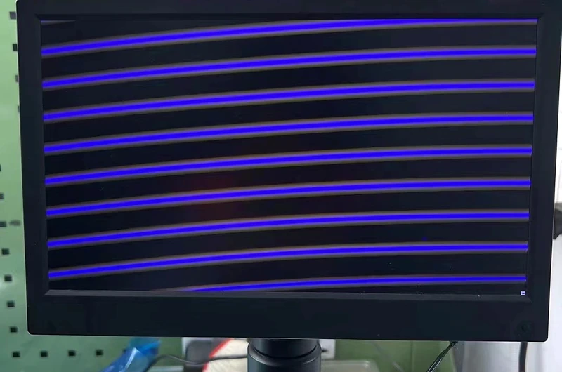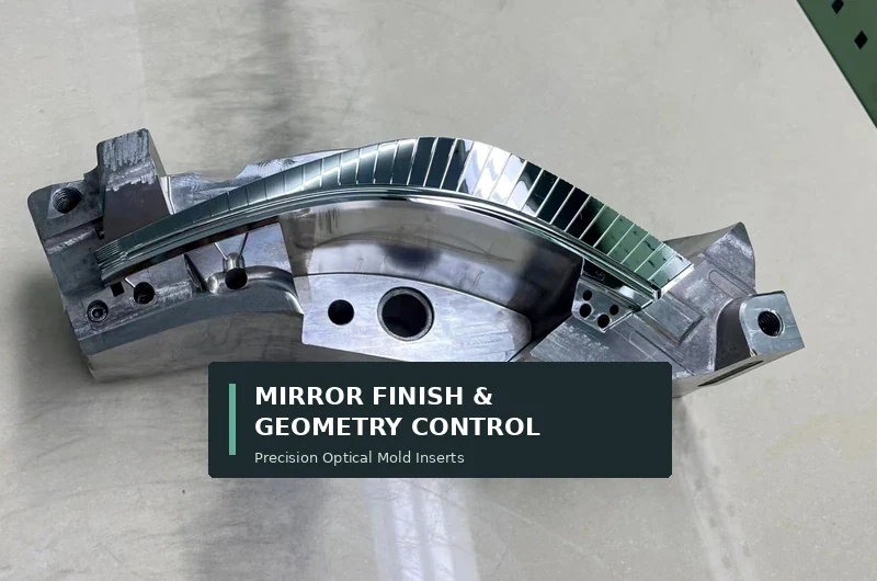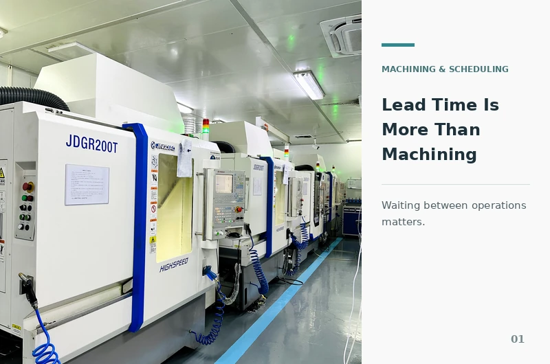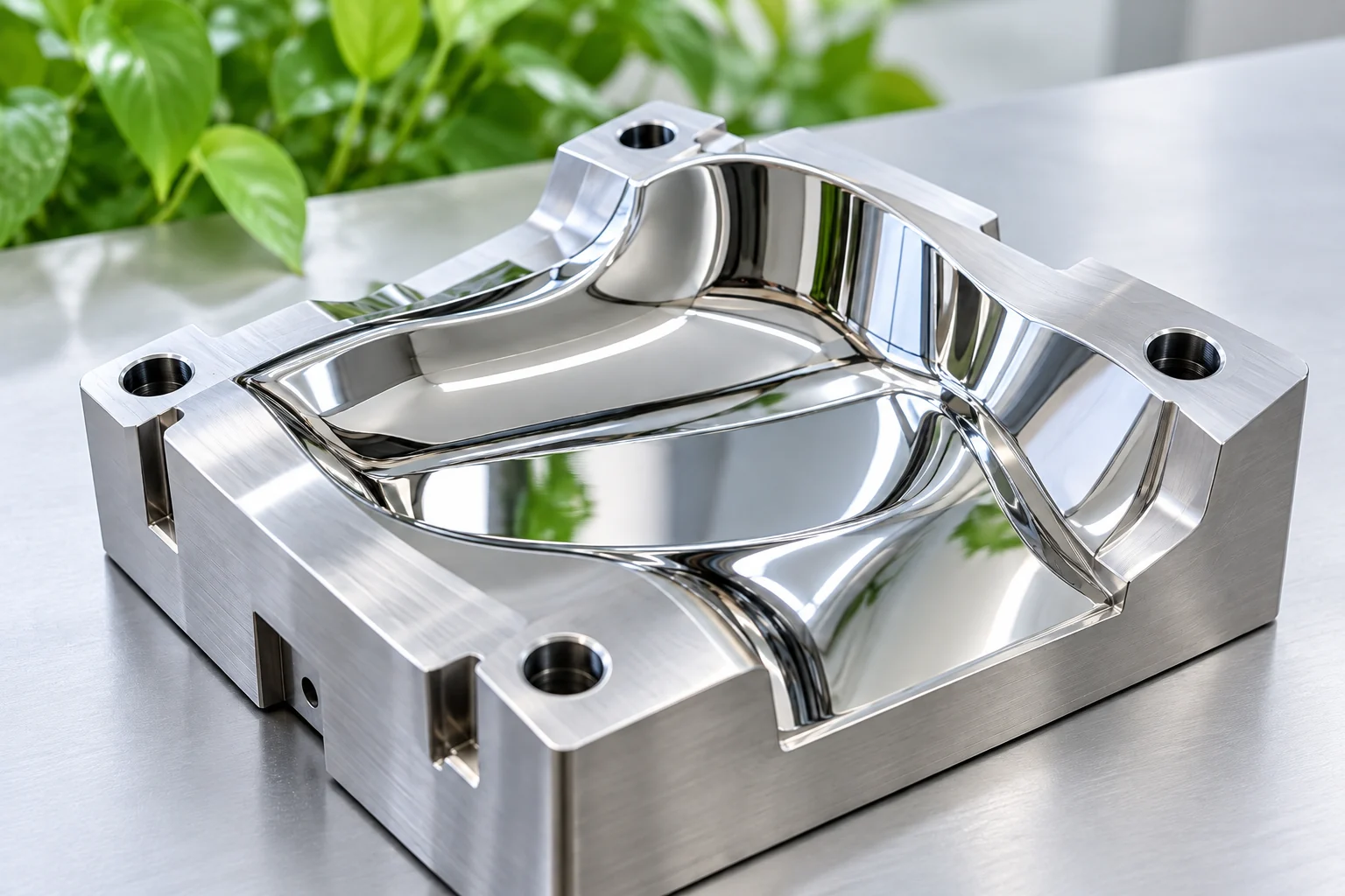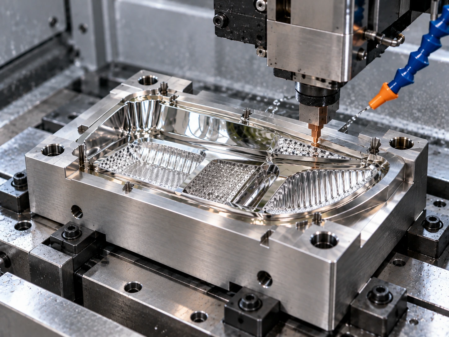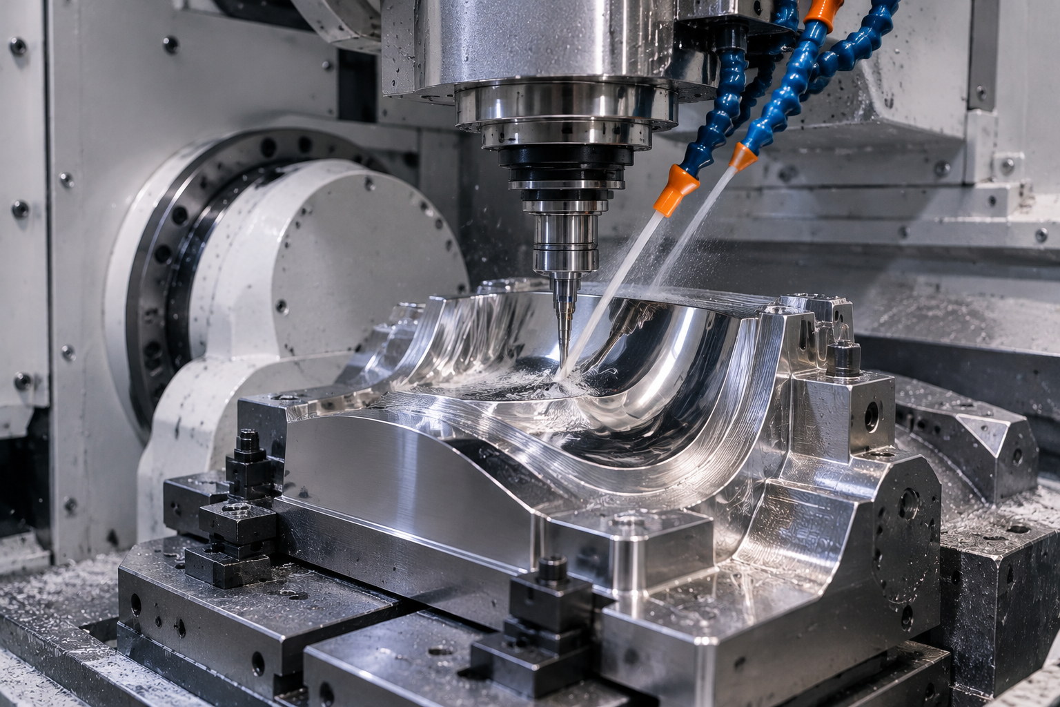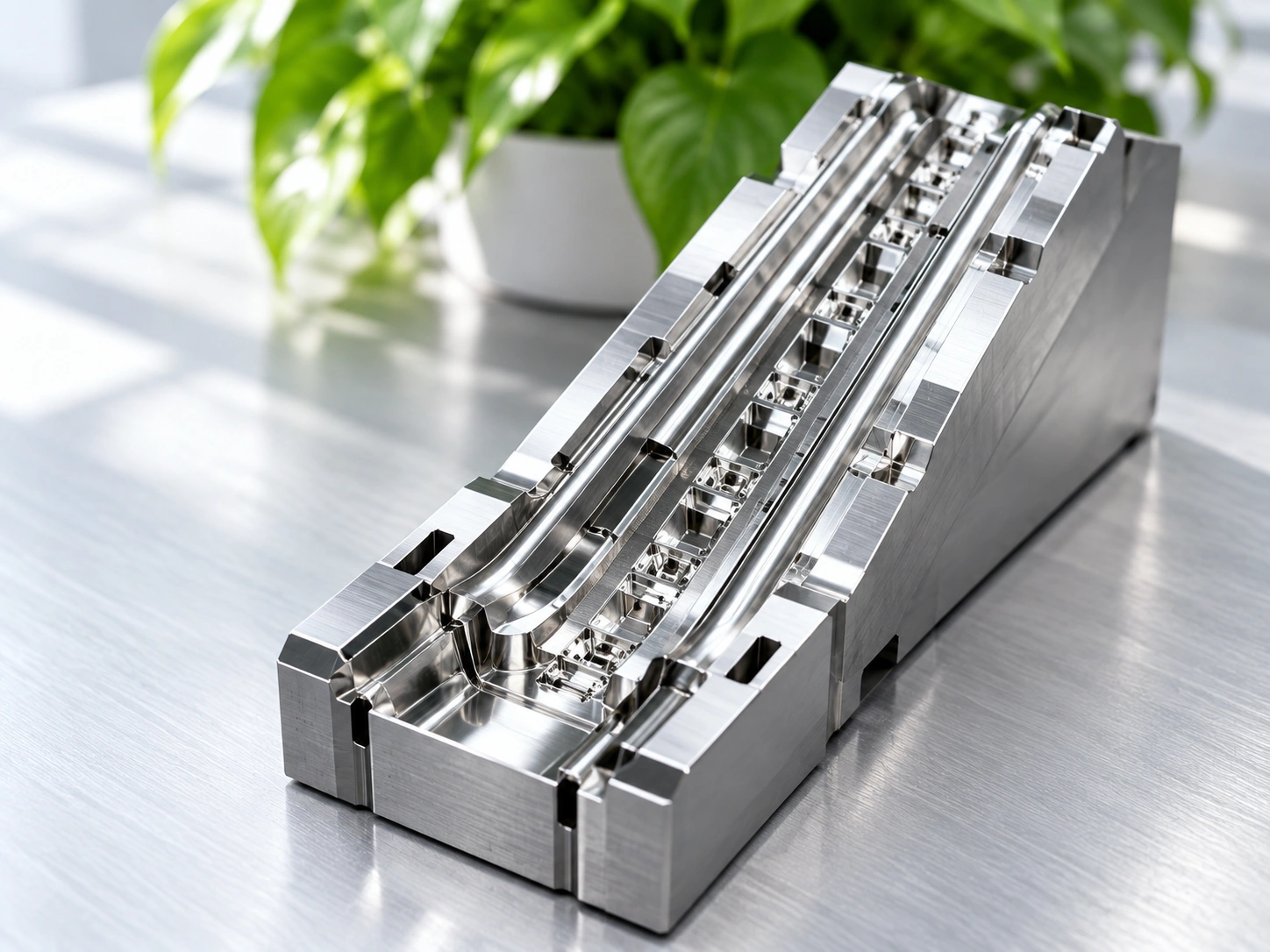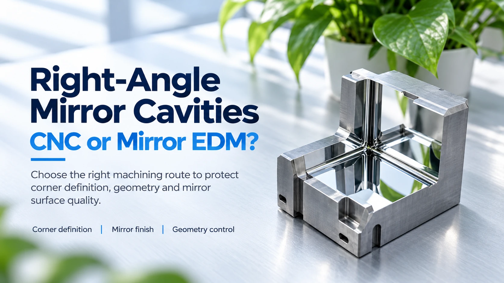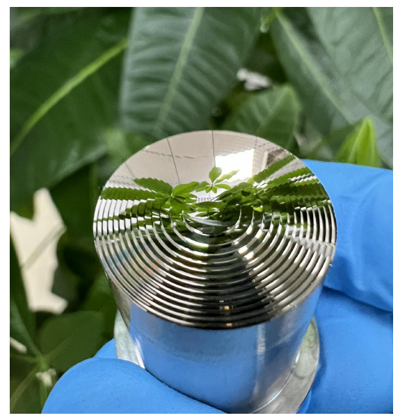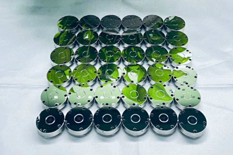
When precision optical mold inserts deviate from their nominal CAD models, the root cause is rarely a single toolpath error. In non-rotationally symmetric and steep aspheric geometries, physical parts drift from mathematical definitions due to coupled dynamic kinematics, diamond tool-edge waviness, discrete CAM interpolation approximations, and workpiece stress relaxation. Addressing this dimensional gap requires deploying 5-axis ultra-precision milling supported by closed-loop on-machine metrology (OMM) and iterative error compensation.
This guide examines the mechanical, kinematic, and computational factors that cause sub-micron form errors (Peak-to-Valley, or PV) and mid-spatial frequency (MSF) waviness during machining, outlining practical methods optical design and manufacturing teams use to achieve CAD-identical fidelity.

The CAD-to-Part Disconnect in Freeform & Aspheric Mold Inserts
In conventional mechanical tooling, part acceptance relies on macro-scale tolerances (typically $\pm 10$ to $\pm 50\ \mu\text{m}$). In optical mold manufacturing—such as inserts used for automotive HUD mirrors, augmented reality (AR/VR) pancake lenses, and compact imaging modules—tolerances shift into sub-micron territory. A form deviation of merely $0.3\ \mu\text{m}$ across a freeform boundary introduces significant wavefront distortion, astigmatism, and modulation transfer function (MTF) degradation in final molded optics.
CAD models describe surfaces using idealized, infinitely smooth mathematical equations (such as NURBS surfaces or continuous polynomial representations). However, the physical process of cutting an insert transfers that continuous math through physical boundaries:
| Transformation Stage | Dominant Physical Mechanism | Impact on Surface Integrity |
| Mathematical Definition | Continuous equations (NURBS, high-order polynomials) | Infinitely smooth nominal reference geometry |
| CAM Post-Processing | Discretization into chordal segments and G-code blocks | Approximated vector paths and chordal error |
| Multi-Axis Kinematics | Dynamic servo response, tracking delays, and Abbe offsets | Tool Center Point (TCP) tracking drift and lag |
| Thermal & Mechanical Loop | Structural loop thermal growth and ambient temperature shifts | Global form sag, focal drift, and dimensional skew |
| Micro-Cutting Mechanics | Single-crystal diamond edge waviness and material strain recovery | Micro-grooves, mid-spatial waviness, and surface relief |
When an insert fails interferometric inspection despite verifying cleanly in CAM simulation, the discrepancy originates within this multi-stage translation chain.
Dynamic Kinematics vs. Static Geometry: The Primary Machining Root Causes
Ultra-precision machine tools feature nanometer-level linear scale feedback, yet static positional precision does not guarantee dynamic multi-axis trajectory accuracy.
Multi-Axis Synchronous Errors and Tracking Lag
Freeform topologies require simultaneous multi-axis motion where tool-workpiece orientation changes continuously along steep gradients. Even when equipped with high-bandwidth linear motor drives, physical axes have distinct moving masses, moments of inertia, and servo response loops:
- Following Errors: Linear and rotary axes exhibit minute tracking delays during high-acceleration toolpath segments, shifting the actual tool center point (TCP) relative to the commanded position.
- Abbe Errors: Angular pitch, yaw, and roll errors in rotary tables or slide ways are amplified over the distance between the guide scale and the cutting tip.
- Rotary Axis Runout: Nanometer-scale axial and radial bearing eccentricities manifest directly as surface profile waviness on non-rotationally symmetric inserts.
Thermal Drift and Micro-Vibrations in Continuous Cutting
Diamond machining freeform optical surfaces with micro-stepovers often demands runtimes stretching over several hours. During extended machining cycles:
- Ambient temperature shifts alter structural loop dimensions. Without strict environmental thermal control (often required within narrow bounds such as $\pm 0.1^\circ\text{C}$ to $\pm 0.5^\circ\text{C}$ in production cleanrooms), structural expansion introduces global form sag or sloping errors.
- Spindle rotation, cooling pumps, and external facility vibrations introduce harmonic micro-chatter, transforming into periodic surface ripples that scatter light in finished optical elements.
CAM Interpolation and Diamond Tooling Deficiencies
The interface between digital CAM data and the diamond cutting edge introduces micro-geometric errors that are often overlooked until post-process optical profilometry.
| Parameter / Factor | Conventional CNC Approach | 5-Axis Ultra-Precision Milling Approach |
| Path Generation Algorithm | Linear point-to-point approximations (G01) | High-order spline or direct NURBS interpolation |
| Trajectory Geometry | Faceted chords approximating curved topology | Smooth, continuous sub-nanometer kinematic motion |
| Surface Profile Outcome | Mid-spatial frequency ripples and visible faceting | High-fidelity optical contour matching CAD math |
| Tool Contact Control | Fixed-orientation variable edge contact | Controlled normal-vector contact on diamond radius |
Chordal Deviation and NURBS-to-G-code Approximation Losses
Standard post-processors convert mathematically smooth CAD curves into series of linear point-to-point vectors (G01 lines).
- If chordal tolerance parameters are set too coarse, the machined mold displays subtle facets (chordal error).
- If chordal tolerance is set extremely fine, CAM files explode into millions of tiny blocks, risking machine CNC buffer starvation, velocity stuttering, and tool dwell marks.
- Advanced manufacturing mitigates this by using direct polynomial/NURBS interpolation or ultra-dense kinematic smoothing filters configured specifically for multi-axis diamond machining.
Diamond Tool Tip Geometry: Nose Radius Waviness and Contact-Angle Shift
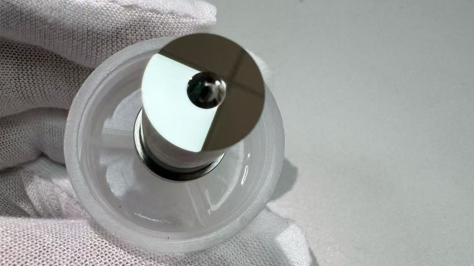
Single-crystal diamond (SCD) cutting tools provide the sharpest feasible cutting edges, but no diamond radius is a pure, perfect circle:
- Tool Waviness: Microscopic irregularities along the cutting edge profile (often $0.05$ to $0.2\ \mu\text{m}$) copy directly onto the workpiece.
- Variable Contact Point: In 3-axis or uncompensated toolpaths, the contact point between the diamond nose and the freeform steep surface moves continuously along the tool arc. Any uncalibrated local radius variation translates immediately into a form height deviation on the insert.
| Error Source | Primary Cause | Typical Physical Surface Manifestation | Impact on Molded Optics |
| CAM Chordal Error | Linear point-to-point approximations of curves | Periodic faceting across varying curvature zones | Mid-spatial frequency ripple, diffraction artifacts |
| Tool Nose Waviness | Sub-micron manufacturing deviations on the diamond radius | Regular microscopic grooves oriented along the feed vector | Increased haze, flare, and reduced optical contrast |
| Thermal Drift | Ambient shifts or spindle motor heat generation | Gradual profile slope, focal length drift, or center sag | Focus shift, spherical aberration |
| Axis Following Error | Unequal servo response across synchronized axes | Corner rounding, profile mismatch at steep-gradient zones | Wavefront astigmatism, peripheral distortion |
Material Mechanics: Stress Relief and Elastic Springback
Even when the tool tip moves along an ideal coordinate path, physical material behavior can distort the finished geometry once machining forces and fixturing are released.
Sub-surface Deformation in Mold Steels and Electroless Nickel (NiP)
Optical mold inserts are frequently manufactured from stainless steel bases plated with high-phosphorus electroless nickel (NiP) to enable diamond cuttablity.
- Although diamond cutting generates minimal mechanical force, micro-cutting creates localized shear stresses along the primary shear zone.
- Insufficiently conditioned substrates or plated layers with high internal tensile/compressive stresses can deform after cut completion.
- Hard inclusions or uneven phosphorus distribution alter local elastic recovery, creating microscopic height variations behind the passing tool tip.
Clamping Distortion: The Clamped-to-Unclamped Shape Shift
Sub-micron optical inserts require rigorous fixturing against cutting dynamics. However:
- Clamping forces inevitably introduce elastic strain inside the insert body.
- If a part is finished in a mechanically stressed state, releasing it from the vacuum chuck or mechanical fixture causes the metal to relax back to its unconstrained equilibrium.
- This elastic rebound alters nominal dimensions, turning a verified in-fixture surface into an out-of-spec component at final optical QA.
Achieving True CAD Fidelity: On-Machine Metrology and Error Compensation
Eliminating form errors requires transitioning from open-loop cutting to closed-loop manufacturing. Incorporating 5-axis ultra-precision milling enables manufacturers to coordinate complex spatial orientations while maintaining the cutting tool normal to the optical surface, minimizing edge contact-angle shifts.
| Process Step | Operational Focus | Technical Action | Quality Objective |
| Step 1: Semi-Finish Cut | Baseline profile generation | Multi-axis diamond milling near final net shape | Establish initial reference surface envelope |
| Step 2: In-Situ OMM | In-machine data collection | High-precision contact or optical probing without unchucking | Capture profile in exact machine coordinates |
| Step 3: Residual Extraction | Dimensional comparison | Algorithmic overlay of measured point cloud vs. nominal CAD | Quantify point-by-point height variance ($\Delta Z$) |
| Step 4: Toolpath Inversion | Path compensation | Invert residual error matrix and recalculate CAM trajectory | Generate anti-deflection corrective G-code |
| Step 5: Micro-Finish Pass | Deterministic removal | Execute compensated pass with fine-depth diamond run | Achieve targeted sub-micron PV and optical finish |
Closed-Loop In-Situ Measurement (OMM)
Rather than unchucking the insert for external measurement—which destroys exact coordinate alignment—advanced optical machining employs on-machine non-contact optical sensors or micro-probing:
- Initial Semi-Finishing: The freeform shape is machined near final net dimensions.
- On-Machine Scanning: An ultra-precise probe scans surface profiles in the machine’s local coordinate reference frame.
- Difference Mapping: The measured coordinate cloud is compared mathematically with the original CAD nominal model, creating an error residual topography map.
Iterative Toolpath Correction
The measured spatial error map is inverted and fed back to the CAM post-processor:
- If a dynamic kinematic lag caused a $0.25\ \mu\text{m}$ deficit at a specific compound angle, the compensated toolpath commands the tool to advance proportionally deeper at that exact vector coordinate.
- A final micro-finishing pass removes the residual deviation.
- Because the workpiece remains undisturbed on its original mounting datum, clamping and re-alignment errors are systematically bypassed.
Pre-Machining Collaboration: DFM Checklist for Optical Engineers
To prevent uncorrectable insert deviations, optical design teams and precision machining specialists should align upstream during the Design for Manufacturability (DFM) review:
- [ ] Provide Native Equation Data Alongside CAD: Export direct mathematical descriptions (e.g., Zernike polynomial coefficients, Chebyshev terms, or raw high-density point clouds) along with STEP/IGES files to prevent boundary discretization errors.
- [ ] Define Spatial Frequency Tolerances: Supplement overall Peak-to-Valley ($PV$) and roughness ($Ra$) values with explicit limits on mid-spatial frequency (MSF) errors or slope error ($\mu\text{rad}$) thresholds to prevent halo-inducing ripples.
- [ ] Specify Coordinated Datum Reference Planes: Include precision-ground mechanical datums directly on the insert perimeter to serve as common reference targets for both the machine coordinate system and external coordinate measuring systems (CMM/interferometers).
- [ ] Incorporate Substrate Stress-Relief Cycles: Ensure workpiece blanks undergo thermal stabilization and stress-relief annealing prior to final diamond cut passes, especially after initial roughing and nickel plating operations.
- [ ] Evaluate Clearance and Tool Aspect Ratios: Confirm that concave features and sharp transitions do not force excessively small tool nose radii, which increase cutting duration and accelerate tool wear.
Key Takeaways
- Deviation is Multifactorial: Insert deviation from CAD geometry stems from a combination of machine dynamic lag, CAM vector approximation, diamond tool edge waviness, and mechanical clamping relaxation.
- The Limitations of Open-Loop Machining: Even high-rigidity ultra-precision platforms require closed-loop compensation to overcome long-duration thermal drifts and complex multi-axis dynamic tracking errors.
- Preserving High-Order Accuracy: Standard linear G-code approximations introduce faceting; complex optical freeforms require continuous higher-order spline/NURBS interpolation or dense kinematic filtering.
- In-Situ Measurement Minimizes Setup Loss: Performing on-machine metrology (OMM) maintains original part coordinate zeroing, enabling reliable sub-micron iterative toolpath error compensation.
Frequently Asked Questions (FAQ)
Can standard optical grinding replace 5-axis ultra-precision milling for freeform surfaces?
Optical grinding performs well on rotationally symmetric aspheres and brittle optical glasses. However, for non-rotationally symmetric freeform geometries—especially on nickel-plated mold cores or non-ferrous reflective metals—5-axis ultra-precision milling using single-crystal diamond tooling provides superior geometric flexibility, eliminates wheel dressing artifacts, and allows direct micro-milling of steep compound slopes without wheel interference.
How is Form Accuracy (PV) verified on non-rotationally symmetric inserts?
Because standard spherical or transmission-flat interferometers cannot match arbitrary freeform wave fronts without dedicated computer-generated holograms (CGHs), verification typically utilizes 3D optical profilometry, tilted-wave interferometers, or multi-axis non-contact scanning probes. These systems compare measured three-dimensional point matrices against the nominal CAD model to compute residual PV and RMS form errors.
What tolerances are realistic when diamond milling freeform mold inserts?
Achievable tolerances depend on part geometry, aspect ratios, substrate stability, and overall physical dimensions. In ultra-precision diamond machining environments with active thermal stability control and on-machine error compensation, form accuracy ($PV$) within sub-micron bands and surface roughness ($Ra$) below $5\ \text{nm}$ are routinely targeted. Exact capability envelopes should be validated based on specific insert material choices and geometric access constraints.