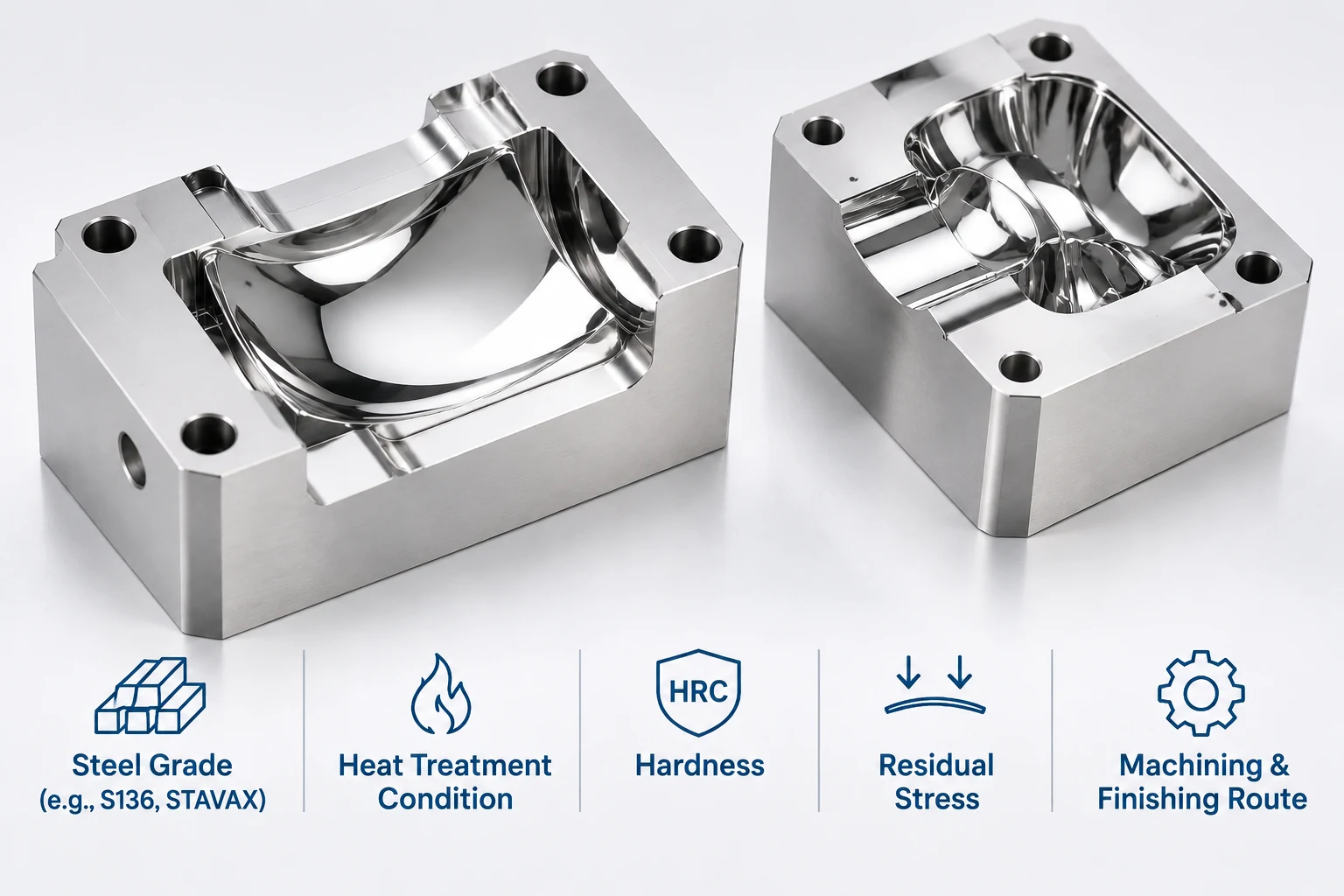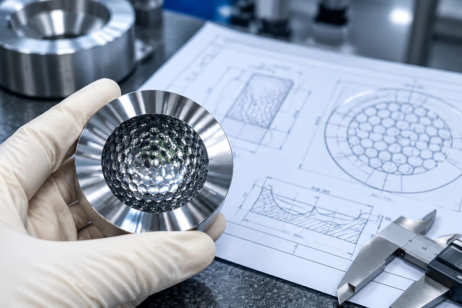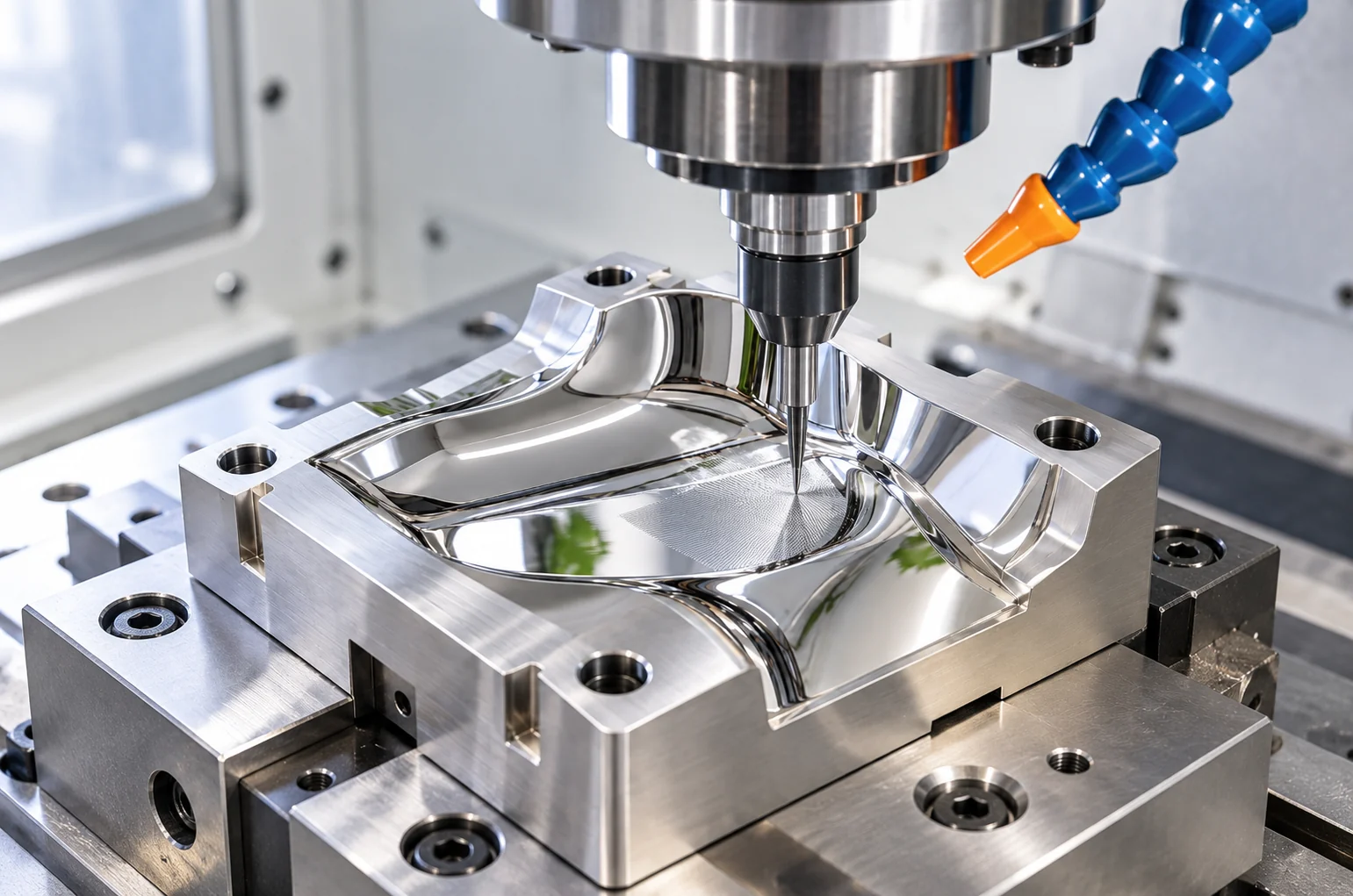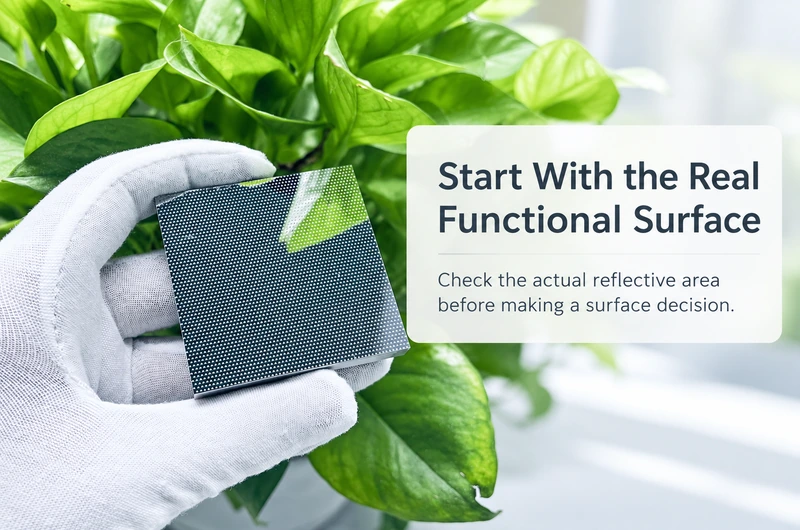
Achieving sub-nanometer surface roughness on optical injection mold inserts requires selecting the proper core material before cutting any metal. When evaluating optical-grade steel versus nickel-phosphorus (NiP) plating for precision mold core machining, the engineering decision centers on tool-material chemistry and tooling lifecycle.
Electroless nickel-phosphorus plating is the benchmark for single-point diamond turning (SPDT), enabling complex aspheric and freeform profiles with nanometer-level roughness. Optical-grade stainless steels provide multi-million-cycle structural longevity and chemical resistance against corrosive resins, but they cannot be cut directly with single-crystal diamond tools due to rapid chemical wear.
Choosing between these options depends on optical surface geometry, resin chemistry, targeted production volumes, and required form accuracy. This technical guide examines microstructural differences, machining compatibility, lifecycle economics, and procurement specifications to help engineering teams specify the right substrate system for their tooling programs.
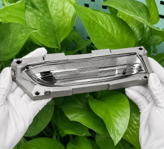
The Optical Mold Core Dilemma: Balancing Surface Finish vs. Tooling Longevity
Optical injection molding demands mold inserts that replicate sub-micron surface profiles across production runs. Imperfections on a mold insert—such as inclusions, micro-voids, carbide clusters, or grain boundary steps—transfer directly into the molded optical component, causing optical distortion, transmission losses, and unwanted stray light.
| Core System Option | Key Capabilities & Strengths | Engineering Constraints |
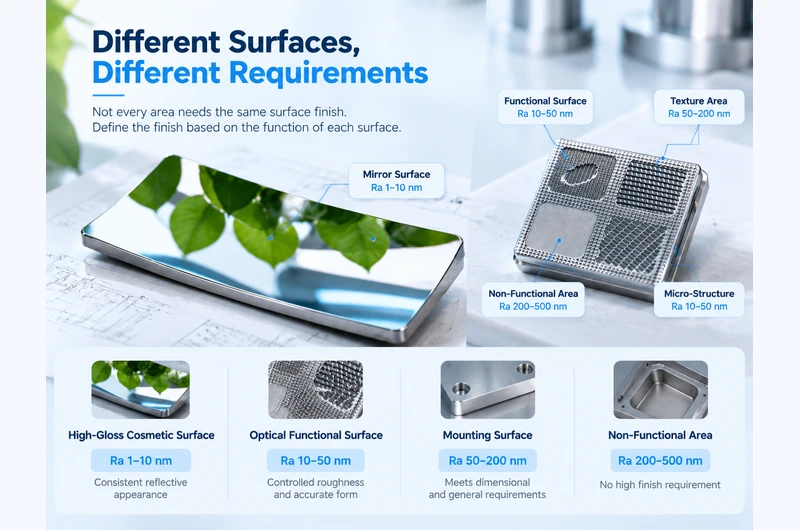
| Electroless Nickel (NiP) Plating | • Fully compatible with Single-Point Diamond Turning (SPDT) • Direct machining of complex freeform and aspheric profiles • Achieves nanometer-level mirror finishes ($Ra < 2\text{–}5\text{ nm}$) | • Limited surface life when molding abrasive or filled resins • Susceptible to scratch damage during improper mold maintenance |
| Optical-Grade Stainless Steel | • Multi-million cycle fatigue and injection shot endurance • Exceptional mechanical resistance to corrosive outgassing resins • High substrate rigidity under intensive clamping tonnages | • Rapid diamond tool wear due to catalytic carbon-iron graphitization • Requires grinding and manual/MRF polishing, limiting complex freeforms |
Tooling engineers face a recurring compromise:
- Surface geometry generation versus material hardness: Creating non-rotationally symmetric, diffractive, or steep aspheric surfaces requires ultra-precision turning. However, the hardest, most wear-resistant mold steels cause severe wear on diamond tooling.
- Initial optical finish versus production life: Soft or amorphous coatings cut smoothly on ultra-precision lathes, but optical steels better endure continuous injection cycles, high clamp tonnages, and automated cleaning procedures.
Balancing these factors dictates whether a mold core should be manufactured entirely from through-hardened optical steel or engineered as a steel substrate with an electroless nickel coating.
Material Fundamentals: Optical-Grade Steel vs. Electroless Nickel-Phosphorus (NiP)
Evaluating the metallurgical structure of these materials reveals why they behave differently during ultra-precision machining.
| Material Feature | Optical-Grade ESR Stainless Steel | High-Phosphorus Electroless NiP Layer |
| Microstructural Phase | Polycrystalline matrix with grain boundaries | Amorphous “metallic glass” (non-crystalline) |
| Defect Mechanism | Grain boundary step-out and potential carbide pull-out | Continuous isotropic shear; zero grain boundaries |
| Typical Hardness | 48–54 HRC (quenched and tempered) | 46–50 HRC (as-plated); up to 60+ HRC (heat-treated)* |
| Primary Finishing Route | Precision grinding, MRF, and deterministic hand lapping | Single-Point Diamond Turning (SPDT) |
| Corrosion Resistance | Superior against moisture, shop air, and plastic outgassing | High against neutral salts; susceptible to harsh acids |
*Note: Heat treating NiP above ~300°C increases hardness but induces crystallization, forming $\text{Ni}_3\text{P}$ precipitates that accelerate diamond tool wear. Plated inserts for diamond turning are typically machined in their as-plated or low-temperature stress-relieved state.
Optical-Grade Stainless Steel
Standard tool steels contain micro-segregations, non-metallic inclusions, and coarse carbide networks. When polished to optical tolerances, hard carbides resist abrasion while the softer surrounding iron matrix erodes, causing orange peel, micro-pitting, and surface relief.
Optical-grade steels—typically refined via Electro-Slag Remelting (ESR) or Vacuum Induction Melting followed by Vacuum Arc Remelting (VIM-VAR)—minimize sulfur, phosphorus, and non-metallic inclusions. ESR steels feature homogeneous microstructures with fine, evenly dispersed carbides. These properties allow the steel to achieve a uniform polish, but the crystalline lattice and micro-scale grain boundaries still influence mechanical material removal at the nanometer scale.
High-Phosphorus Electroless Nickel (NiP)
Electroless nickel plating used in precision optics is an autocatalytic chemical reduction process that deposits a nickel-phosphorus alloy without electrical current.
For diamond turning applications, optical mold manufacturers rely on high-phosphorus formulations (typically 10% to 13% phosphorus by weight). At this phosphorus level, the alloy solidifies into an amorphous, non-crystalline “metallic glass” structure. Because it lacks crystal grains, grain boundaries, and carbide precipitates, the alloy does not produce localized pull-out or directional cleavage during cutting. It yields continuous micro-chips under a single-crystal diamond edge, enabling uniform nanometer-scale surface finishes.
Machinability and Process Fit: SPDT Diamond Turning vs. Ultra-Precision Grinding
Material selection directly determines which machine tools, cutting instruments, and kinematic strategies can be used during precision mold core machining.
Why Ferrous Steels Cannot Be Directly Diamond Turned
Single-crystal natural or synthetic diamond cutting tools deliver edge sharpness with cutting-edge radii below 20 nanometers. However, diamond is pure carbon. When a diamond tool cuts ferrous alloys like stainless steel:
- High contact pressures and localized cutting-zone temperatures trigger a chemical affinity reaction between carbon and iron.
- Iron acts as a catalyst, transforming the diamond crystal lattice into graphite.
- Rapid chemical diffusion wears away the diamond cutting edge within seconds, causing micro-chipping, loss of profile accuracy, and torn surface finishes.
While specialized approaches exist—such as ultrasonic vibration-assisted machining (UVAM) or diamond turning in cryogenic/carbon-saturated atmospheres—they require specialized setups and introduce processing limits on complex mold geometries.
| Tool-Material Interaction | Reaction Mechanism | Resulting Cutting Outcome |
| Diamond Tool + Ferrous Steel | Catalytic transformation where iron triggers carbon graphitization at elevated cutting heat | Rapid cutting-edge micro-chipping, extreme tool wear, and degraded surface finish |
| Diamond Tool + Amorphous NiP | Ductile-regime chip formation with zero chemical graphitization | Preserved nanometer tool edge, continuous micro-chips, and mirror-finish profile |
Electroless Nickel as the Standard for SPDT
High-phosphorus NiP deposits do not react catalytically with carbon. The amorphous alloy exhibits consistent shear behavior in the ductile cutting regime. When paired with an ultra-precision lathe, single-point diamond turning machines aspheric surfaces, off-axis parabolas, and continuous freeform topographies directly onto a NiP-plated insert. Form errors remain within sub-micron tolerances, eliminating the need for iterative manual polishing that could degrade profile accuracy.
Precision Machining Routes for Optical Steels
When optical components must be molded directly from tool steel, fabricators cannot rely on standard SPDT turning. Instead, they use alternative manufacturing routes:
- Ultra-Precision Micro-Grinding: Multi-axis CNC grinders using vitrified or resin-bonded cubic boron nitride (CBN) or fine diamond wheels grind rotationally symmetric or shallow aspheric geometries.
- Sub-Aperture and Magnetorheological Finishing (MRF): Fluid-based polishing systems use magnetic fields to guide abrasive slurries across the surface, correcting form errors on steel without inducing subsurface damage.
- Multi-Stage Mirror Lapping and Hand Polishing: Skilled toolmakers use progressively finer diamond suspensions (from 3 µm down to sub-micron pastes) to polish out grinding marks. While effective on planar flats or basic spheres, manual polishing struggles on complex aspheres and freeform profiles because it can roll edges and degrade figure accuracy (PV).
Optical Surface Performance: Roughness (Ra) and Form Accuracy (PV)
The functional quality of an optical mold core is evaluated using two metrics: surface roughness (finish) and form error (profile accuracy).
| Performance Metric | Electroless NiP via SPDT Turning | Optical Steel via Precision Polish |
| Surface Roughness ($Ra / Sa$) | Consistently $Ra < 1.0\text{–}3.0\text{ nm}$ ($Sa < 2.0\text{–}4.0\text{ nm}$) | $Ra \approx 3.0\text{–}8.0\text{ nm}$ on complex geometries |
| Form Accuracy ($PV$) | Typical peak-to-valley of $0.15\text{–}0.4\text{ }\mu\text{m}$ across clear aperture | $PV > 0.5\text{–}1.0\text{ }\mu\text{m}$ due to manual polishing edge roll |
| Micro-Structure Fidelity | Excellent for Fresnel patterns and microlens arrays | Limited due to abrasive slurry rounding off fine edges |
| Post-Processing Requirement | Negligible; typically ready for molding after SPDT | Extensive multi-step lapping and iterative optical metrology |
Surface Roughness (Ra / Sa)
- Electroless Nickel via SPDT: Diamond turning an amorphous NiP layer consistently achieves surface roughness values of $Ra < 1.0\text{ to }3.0\text{ nm}$ ($Sa < 2.0\text{ to }4.0\text{ nm}$). This finish prevents visible haze and minimizes chromatic and spatial scattering in imaging optics across visible and infrared wavelengths.
- Optical Stainless Steel via Mechanical Polishing: High-grade ESR steels can achieve surface finishes below $Ra\text{ }5.0\text{ nm}$ on flat or spherical profiles through automated lapping and micro-polishing. However, on concave aspheric surfaces or intricate mold core features, micro-roughness typically stabilizes around $Ra\text{ }4.0\text{ to }8.0\text{ nm}$, largely due to variations in micro-grain abrasion rates.
Form Accuracy (Peak-to-Valley / PV)
Form accuracy measures how closely the machined physical mold core matches the optical engineer’s mathematical surface equation.
- NiP Diamond Turning: Because SPDT operates on hydrostatic or aerostatic bearing slides with nanometer encoder feedback, the tool path generates aspheric and freeform equations directly. Typical peak-to-valley ($PV$) values range from $0.15\text{ }\mu\text{m}\text{ to }0.4\text{ }\mu\text{m}$ across moderate clear apertures, with minimal post-machining touch-up required.
- Steel Processing: Achieving comparable $PV$ on hardened steel requires iterative cycles of metrology (e.g., 3D profilometry or stitching interferometry) paired with deterministic polishing. Hand polishing often removes material unevenly near the edges of an optical aperture, distorting the optical wave-front ($PV > 0.5\text{–}1.0\text{ }\mu\text{m}$) even when the surface appears visually clear.
Production Durability: Shot Life, Resin Compatibility, and Lifecycle Cost
While nickel plating excels at precision profile generation, substrate durability under injection molding conditions must also be considered.
| Polymer & Additive Type | NiP Plating Endurance Impact | Optical-Grade Steel Endurance Impact |
| Optical Resins (PMMA, PC, COP, COC) | Delivers 100,000 to 300,000+ stable cycles with zero haze | Runs 1,000,000+ production cycles with minimal surface wear |
| Abrasive Resins (Filled / High-Viscosity) | Micro-scratching occurs quickly on the 46–50 HRC surface | Resists abrasive drag marks due to through-hardened matrix |
| Corrosive Resins (Halogenated / Acid-Releasing) | Risk of vapor penetration through pores, leading to blisters | High chromium/ESR metallurgy resists chemical attack |
Production Volume and Shot Longevity
Hardened optical stainless steel offers superior mechanical endurance. A solid, through-hardened steel insert (50–54 HRC) can run hundreds of thousands to several million molding cycles without degrading optical shut-offs or scratching polished surfaces, provided the mold is operated and cleaned properly.
Conversely, an electroless nickel coating is a surface layer—typically deposited at thicknesses between 50 µm and 150 µm. Over extended production runs, cyclic mold clamp pressures, thermal cycles, and operator wipe-downs can cause localized wear. For high-volume commodity optical production (such as standard LED lighting optics running millions of cycles), solid tool steels or hardened alloys often prove more economical over time.
Rework and Refurbishment Economics
- Stripping and Re-Plating NiP: A damaged NiP-coated insert does not require rebuilding from scratch. The remaining nickel layer can be chemically stripped without attacking the base steel substrate. The core is then re-plated and re-machined on an SPDT lathe to original blueprint specifications. This refurbishing cycle can often be performed multiple times on the same substrate, lowering total tooling development costs.
- Refurbishing Solid Steel: Correcting scratches or micro-dents on solid steel requires stone polishing, laser welding, or re-grinding. These adjustments alter reference datums and optical thickness dimensions, often requiring adjustments to the mating mold plates.
Engineering Decision Framework: Selecting the Optimal Core System
Choosing between solid optical steel, an electroless nickel plating, or a hybrid configuration depends on part geometry, optical application, and production scale.
| Primary Optical Surface Geometry | Target Shot Volume & Resin Type | Recommended Material Configuration | Manufacturing Route |
| Aspheric / Freeform / Toric | $< 300\text{k}$ shots; clean optical resins (PMMA/COP/PC) | Electroless NiP on Steel Base | Rough turning $\rightarrow$ NiP plating $\rightarrow$ SPDT finish |
| Aspheric / Freeform / Toric | $> 500\text{k}$ shots; aggressive/filled polymers | Hybrid System (Steel + NiP + PVD Overcoat) | SPDT on NiP layer $\rightarrow$ Protective thin-film PVD |
| Planar / Simple Spherical | Multi-million shots; high-volume production | Solid Optical-Grade ESR Steel | Precision micro-grinding $\rightarrow$ Automated MRF/lapping |
| Micro-Structured (Fresnel / MLA) | Any production volume; optical-grade resins | Electroless NiP on Copper or Steel Base | Precision tool micro-machining via multi-axis SPDT |
Application Selection Matrix
| Optical Component Type | Recommended Core Material System | Manufacturing Process | Primary Selection Rationale |
| Mobile Phone Camera Lens (Aspheric) | Stainless Steel Base + High-P NiP Coating | Rough machining, stress relief, NiP plating, SPDT | Requires sub-micron form accuracy ($PV < 0.2\text{ }\mu\text{m}$) and $Ra < 2\text{ nm}$; unachievable on steel alone. |
| AR/VR Pancake or Waveguide Lens | Copper Alloy or Pre-hardened Steel + NiP | Precision turn, NiP plate, SPDT, optional post-polish | Strict wavefront error limits demand direct diamond generation of complex freeform curves. |
| Automotive Headlamp Thick-Lens / Light Pipe | Through-Hardened ESR Optical Steel | 5-axis high-speed CNC milling, micro-grinding, automated polish | High shot volumes, large dimensions, and high thermal demands favor solid structural steel. |
| Laser Collimator Lens (Spherical) | Solid Stainless Steel (420 ESR / Stavax type) | CNC roughing, heat treat, ultra-precision grinding, MRF | Spherical shapes are easily generated by automated planetary polishers; solid steel extends tool life. |
| Automotive Sensor Lens (LIDAR / ADAS) | High-Toughness Steel Base + NiP Plating | Precision machining, electroless NiP plate, SPDT | Balances structural integrity under high clamp loads with the nanometer surface accuracy needed for infrared transmission. |
The Hybrid Core Architecture
A common standard for precision optics combines both approaches:
- Base Substrate: A high-stability stainless steel base (pre-hardened or through-hardened) or copper alloy provides overall structural rigidity, high compressive strength, and uniform heat dissipation.
- Optical Face Layer: A uniform 75 µm to 125 µm layer of high-phosphorus electroless nickel is applied to the front working face. This layer is then diamond-turned to generate the final optical profile.
This hybrid approach isolates optical surface generation from the structural demands of the mold base.
Technical DFM and Sourcing Checklist: RFQ Specifications
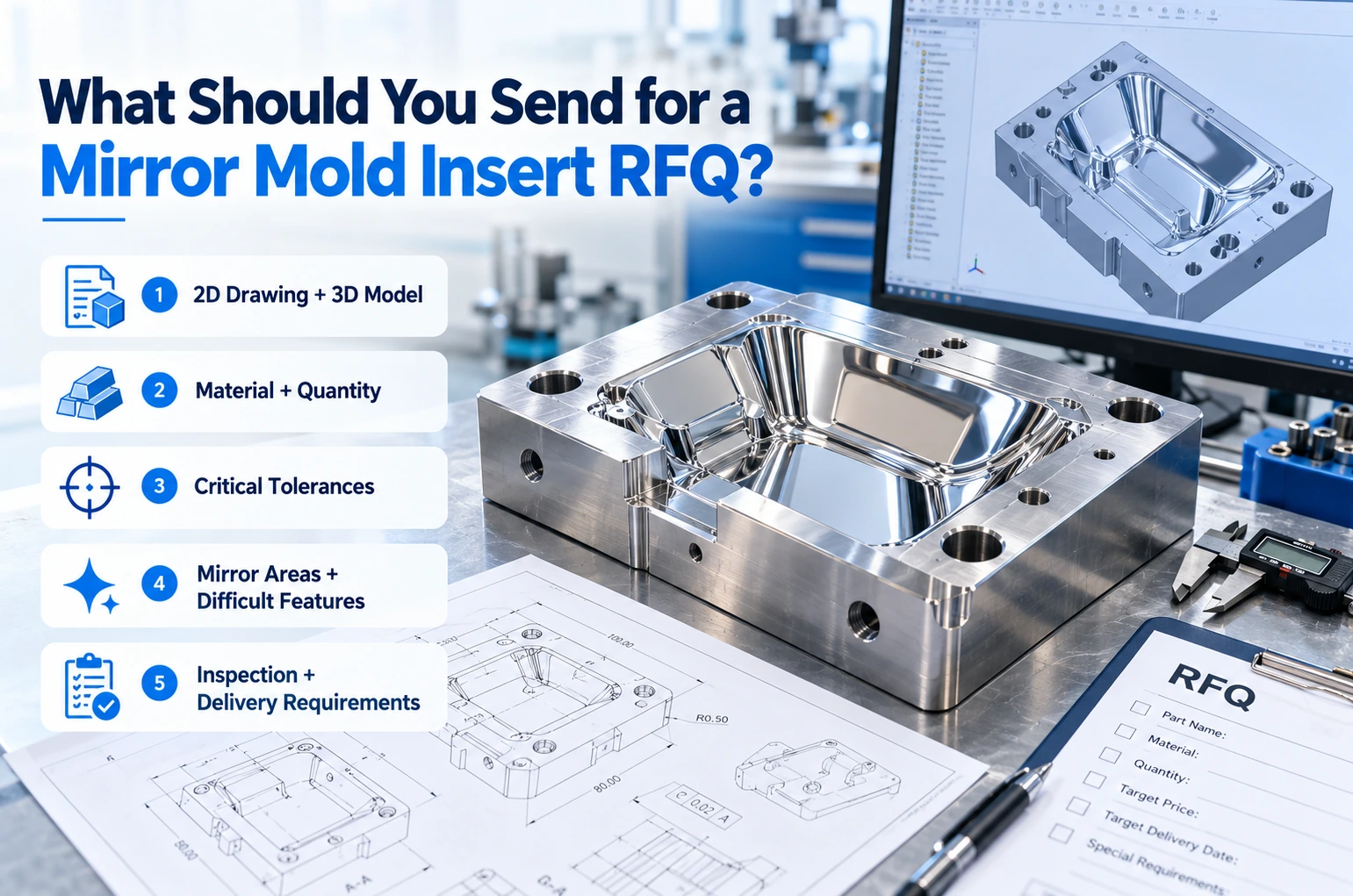
To avoid engineering delays when outsourcing custom optical mold core insert machining, procurement and design teams should document exact material grades, heat treatment protocols, and plating parameters directly on 2D engineering drawings.
| RFQ Engineering Category | Inspection & Specification Requirement | Recommended Value / Engineering Note |
| 1. Base Substrate Metallurgy | Base alloy grade and melting method | Certified DIN 1.2083 ESR / AISI 420 ESR (Ultrasonic Class A/B) |
| 2. Thermal & Dimensional Stability | Stress-relieving and cryogenic cycling | Multi-stage stress relief; sub-zero treatment ($-80^\circ\text{C}$) before final turn |
| 3. Electroless Nickel Plating | Phosphorus concentration by weight | $10.5\%\text{ to }12.5\%\text{ P}$ (Amorphous phase guaranteed) |
| Pre-machining and post-machining thickness | $75\text{–}125\text{ }\mu\text{m}$ as-plated; $\ge 40\text{ }\mu\text{m}$ residual thickness after SPDT | |
| De-hydrogenation baking process | $180\text{–}200^\circ\text{C}$ for $\ge 4\text{ hours}$ to prevent hydrogen embrittlement | |
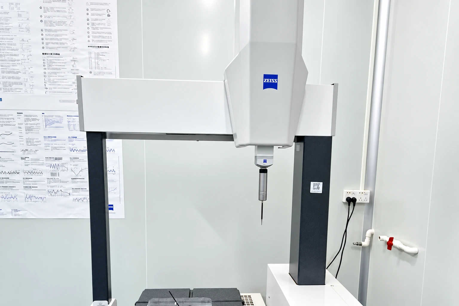
| 4. Optical Surface Verification | Surface micro-roughness ($Ra / Sa$) | Optical profilometer report demonstrating $Ra < 2.0\text{ nm}$ |
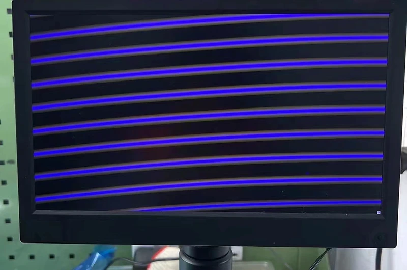
| Form accuracy ($PV$) and slope error | Laser interferometer fringe analysis over clear aperture ($PV < 0.3\text{ }\mu\text{m}$) | |
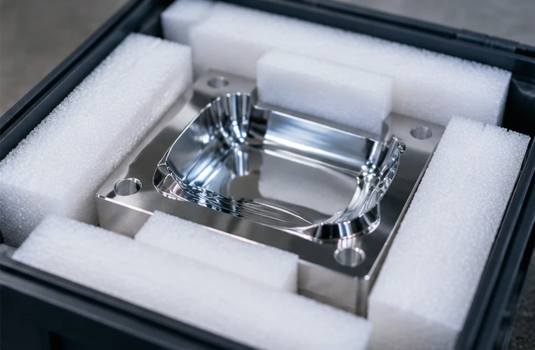
| 5. Packaging & Preservation | Non-contact protective transport | Individual recessed pocket carriers, nitrogen flush or vapor-phase inhibitors |
Conclusion: Engineering Material Strategies for Optical Molding
Specifying materials for optical mold inserts involves balancing processing capabilities with operational life. When manufacturing complex aspheric, toric, or freeform surfaces that require sub-nanometer roughness ($Ra < 2\text{ nm}$) and tight $PV$ profiles, using a high-phosphorus electroless nickel coating paired with single-point diamond turning (SPDT) remains the most capable approach. When production requires multi-million-cycle durability with flat or spherical profiles, through-hardened optical-grade ESR steels offer the necessary wear and corrosion protection.
Many modern optical systems use a hybrid design—a stabilized steel substrate coated with precision-machined electroless nickel. This configuration provides the structural rigidity required for injection cycling alongside the machinability needed for nanometer-level optical surfaces.
Key Takeaways
- Diamond Turning Feasibility: Direct single-point diamond turning of standard optical steel causes rapid tool wear from chemical graphitization. Electroless nickel plating provides an amorphous, grain-free structure that machines smoothly via SPDT.
- Optical Finish Boundaries: Amorphous NiP layers routinely achieve $Ra < 2.0\text{ nm}$ on aspheric and freeform profiles without hand-polishing. Optical-grade steels typically reach $Ra\text{ }4.0\text{–}8.0\text{ nm}$ on complex shapes, though they can achieve finer finishes on simple planar forms.
- Mold Longevity: Hardened ESR stainless steel inserts withstand higher production volumes, abrasive resins, and aggressive cleaning. NiP coatings offer intermediate life (often 100k–300k+ shots with unfilled resins) and can be chemically stripped, re-plated, and re-cut onto the original substrate.
- Optimal Design Approach: For freeform and aspheric optics, the industry standard relies on a hybrid construction: a thermally stable steel core base layered with 75–125 µm of high-phosphorus NiP.
Frequently Asked Questions
Can optical-grade stainless steel be diamond turned directly without plating?
Direct diamond turning of ferrous alloys causes accelerated tool wear due to chemical reactions between the iron substrate and the carbon diamond tool under cutting temperatures. While specialized technologies like ultrasonic vibration-assisted machining (UVAM) or cryogenic setups reduce this effect, they add process complexity and setup costs. For standard SPDT operations, an electroless nickel coating remains the preferred choice.
What is the recommended phosphorus content for electroless nickel coatings in SPDT?
High-phosphorus formulations with 10% to 13% phosphorus by weight are recommended. At these levels, the deposited alloy forms an amorphous, non-crystalline phase without grain boundaries, preventing micro-cleavage during diamond cutting. Phosphorus levels below 9% create mixed crystalline microstructures that accelerate diamond edge chipping.
How thick should the nickel-phosphorus layer be before machining?
A typical as-plated NiP layer ranges between 75 µm and 125 µm. This provides enough stock for roughing, semi-finishing, and final diamond passes while accounting for minor geometric runout. Leaving roughly 40 µm to 60 µm of plating after final machining maintains structural integrity and corrosion protection across the steel substrate.
How does mold steel purity affect polishability?
Standard steels contain microscopic sulfur inclusions, oxides, and carbide segregations. During optical polishing, softer matrix material erodes faster than these hard inclusions, causing pitting, comet tails, and orange peel. Steels refined through Electro-Slag Remelting (ESR) minimize non-metallic impurities and feature fine, uniform carbide dispersions that allow the surface to polish out evenly.
How many times can a nickel-plated mold insert be reconditioned?
In most cases, an insert can be stripped and re-plated multiple times, provided the underlying steel substrate remains undamaged. The worn nickel layer is chemically stripped using specialized solutions that do not etch the base metal, then re-plated and re-turned to original drawing dimensions.