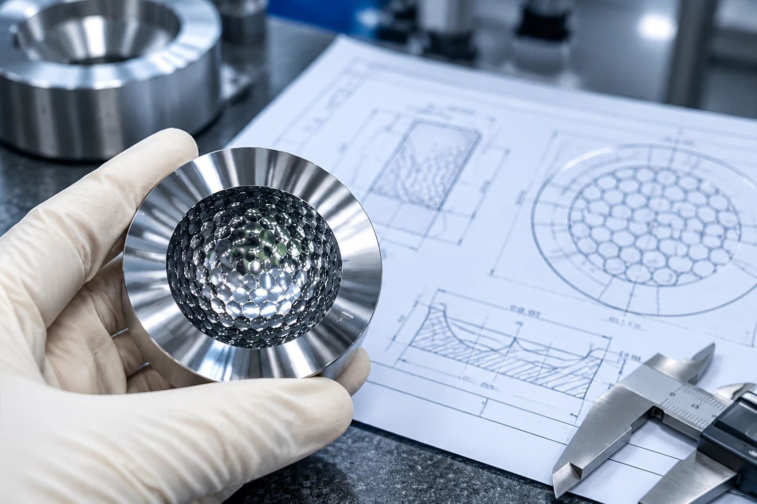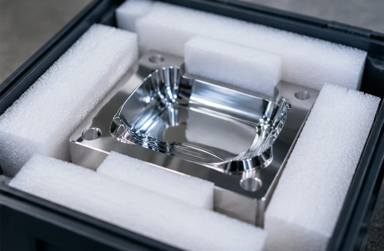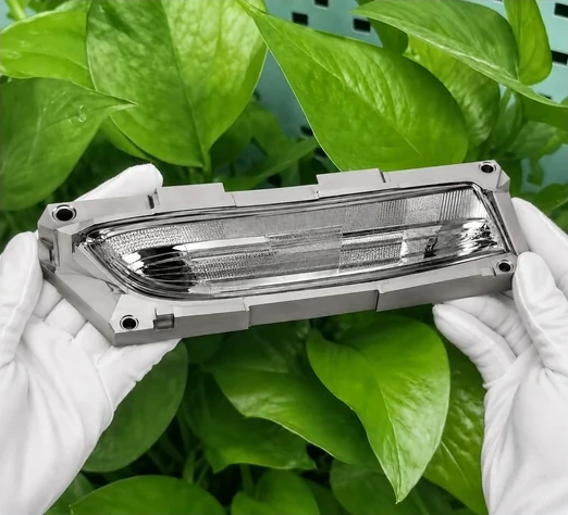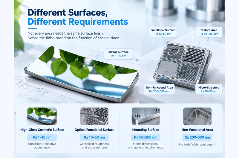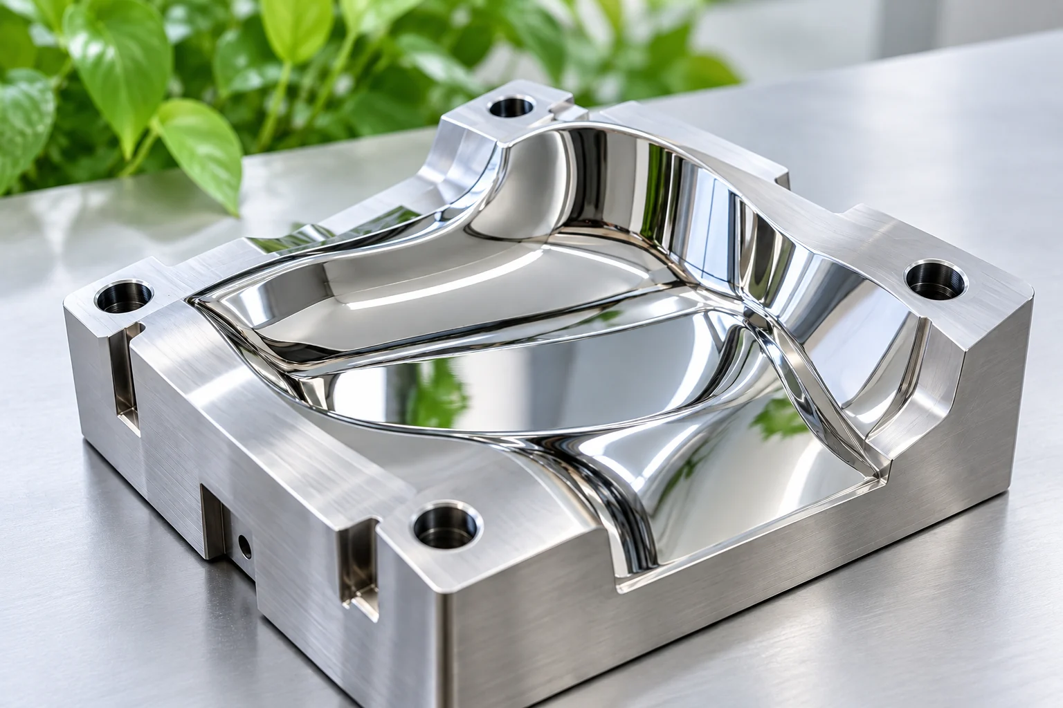
Selecting the right process for precision mold core machining comes down to four critical factors: surface finish requirements, part geometry, workpiece material, and the tolerance for secondary polishing.
Single-Point Diamond Turning (SPDT) produces sub-nanometer, mirror-like surface finishes directly on rotational parts made from non-ferrous metals or electroless nickel plating, eliminating post-polishing. In contrast, 5-axis ultra-precision CNC milling provides the multi-axis kinematic freedom required to cut complex, non-rotationally symmetric freeform geometries and micro-structures directly into hardened mold steels.
Understanding the technical boundaries between SPDT and 5-axis ultra-precision milling ensures you achieve optical-grade form accuracy without inflating manufacturing cycle times or machining budgets.
The Optical Tooling Challenge: Balancing Surface Finish, Geometry, and Material Constraints
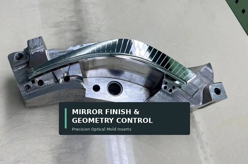
Tooling for injection-molded precision optics—such as automotive headlamp arrays, camera lens elements, head-up display (HUD) mirrors, and virtual reality (VR) waveguide inserts—demands extreme surface integrity. Mold inserts must replicate optical surfaces with sub-micron form accuracy (Peak-to-Valley or PV error) and nanometer-scale surface roughness ($Ra$ or $Sa$).
In conventional mold making, machined cavities undergo manual or robotic abrasive polishing to achieve a mirror finish. In optical manufacturing, however, aggressive post-polishing rounds sharp edges, degrades geometric form accuracy, and ruins precise optical prescriptions.
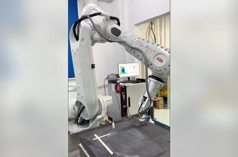
As a result, modern tooling engineers rely on deterministic machining: generating the final optical surface directly on the machine tool.
The engineering decision between 5-axis ultra-precision milling and SPDT is not about which machine is superior overall. It is about matching the physical physics of the cutting process to the core insert’s optical design, substrate hardness, and dimensional specifications.
Technology Fundamentals: Kinematics and Material Suitability
Single-Point Diamond Turning (SPDT): Mechanisms and the Ferrous Metal Limit
SPDT relies on a single-crystal natural or synthetic diamond tool mounted on an ultra-stiff, air- or hydrostatic-bearing lathe spindle. The machine moves along controlled linear axes with sub-nanometer feedback resolution. Because diamond cutting edges can be honed to atomic sharpness, SPDT shears metal chips at thicknesses smaller than the cutting edge radius, creating an optical mirror finish directly off the machine tool.
However, SPDT has a well-known chemical limitation: diamond is carbon. When cutting ferrous materials such as standard hardened tool steels (e.g., Stavax, 420 stainless steel), the extreme friction, temperature, and pressure at the shear zone cause a chemical reaction. Carbon atoms from the diamond tool diffuse into the iron matrix of the steel, leading to catastrophic tool wear within seconds.
For this reason, SPDT mold cores rely on:
- Non-ferrous substrates (copper, brass, aluminum)
- Polymer optical prototypes (PMMA, Zeonex, polycarbonate)
- Hardened steel cores electroplated with a layer of electroless nickel-phosphorus (NiP), typically 50 to 100 microns thick, which the diamond tool cuts cleanly without chemical degradation.
5-Axis Ultra-Precision Milling: Multi-Axis Kinematics and Hardened Steel Machining
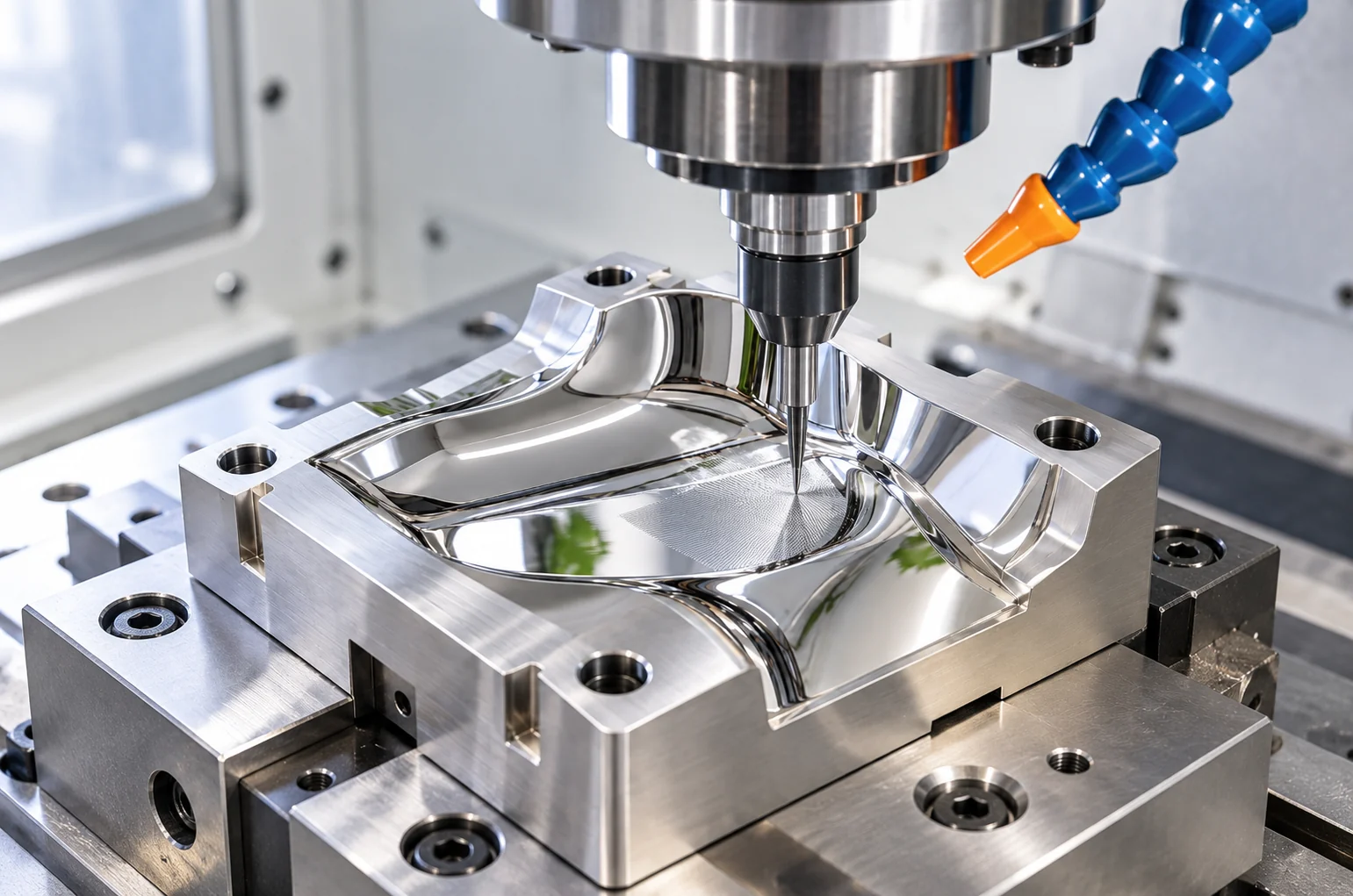
Ultra-precision 5-axis milling utilizes micro-endmills (often solid carbide, PCD, or diamond-coated endmills) rotating at high spindle speeds (frequently 40,000 to 100,000 RPM or higher) across five synchronized degrees of freedom ($X, Y, Z$ and two rotary axes, typically $B$ and $C$).
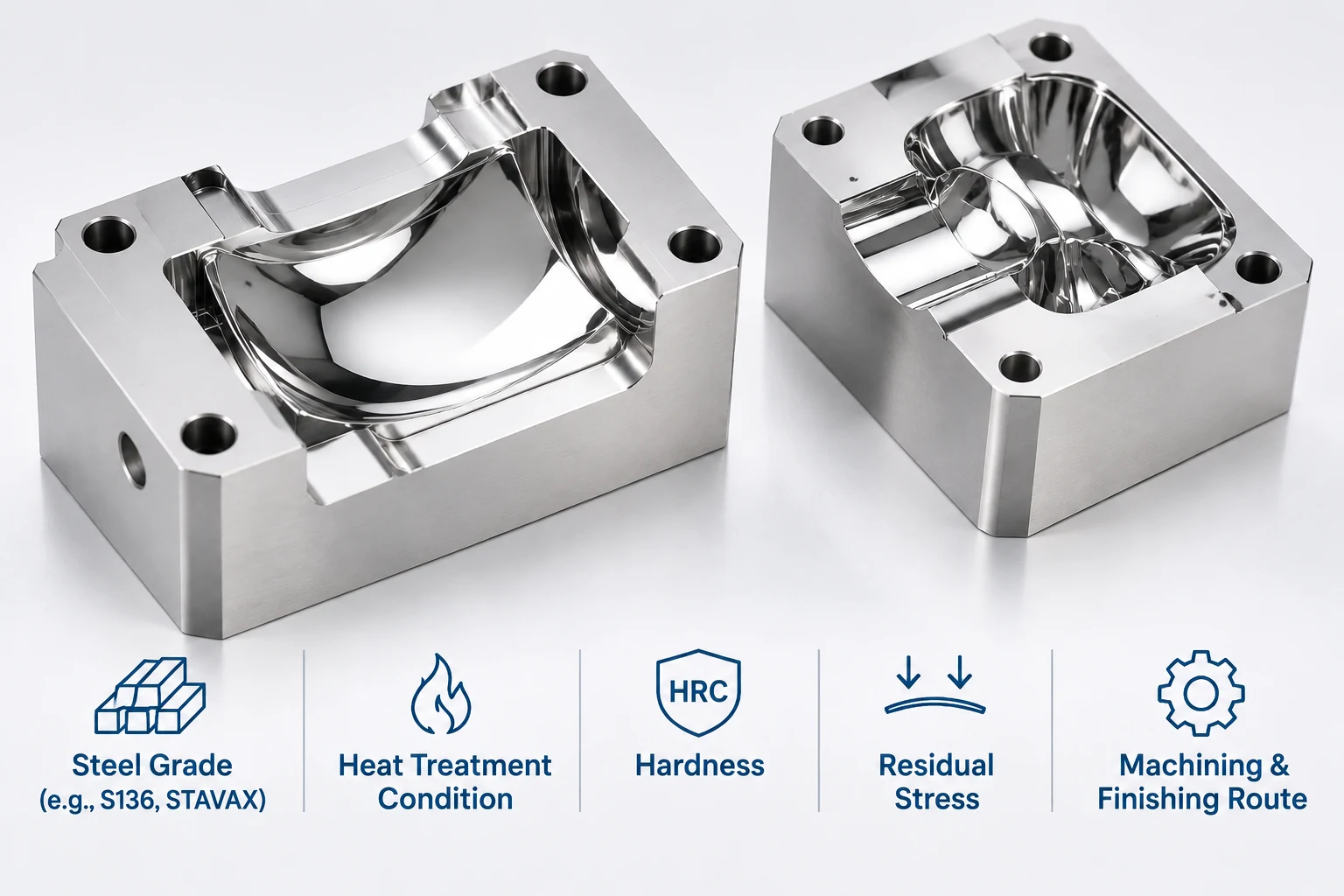
Unlike SPDT, ultra-precision milling can cut directly into hardened stainless mold steels (52–54 HRC or higher) without causing rapid chemical breakdown of carbide or coated cutting tools. The multi-axis toolpath allows the endmill to maintain an optimal contact angle across deep cavities, steep drafts, and irregular optical features that a traditional turning tool cannot reach.
Material Compatibility Matrix for Optical Mold Cores
| Workpiece Material | SPDT Compatibility | 5-Axis Ultra-Precision CNC Compatibility | Engineering Considerations |
| Hardened Mold Steel (e.g., 420 SS, Stavax) | Unsuitable (Severe diamond wear) | Excellent | Standard substrate for high-volume injection molds; CNC eliminates need for nickel plating. |
| Electroless Nickel Plating (NiP) | Excellent | Good | Standard workflow for diamond-turned optical cores; requires plating and substrate preparation. |
| Oxygen-Free High-Conductivity Copper (OFHC) | Excellent | Good (Burr control required) | Common for reflective mirror cores and experimental prototypes. |
| Aluminum Alloys (e.g., 6061-T6) | Excellent | Good | Suitable for rapid prototyping and low-pressure molding inserts. |
| Optical Polymers (PMMA, COP, PC) | Excellent | Good | Used for direct-cut optical prototypes rather than production mold tooling. |
Head-to-Head Comparison: Form Accuracy, Surface Roughness, and Geometrical Freedom
When evaluating precision mold core machining for an optical component, compare the physical capabilities of each process across three core metrics: achievable surface roughness, form accuracy, and geometric versatility.
Geometric Spectrum and Recommended Machining Technology
| Geometric Category | Typical Optical Features | Kinematic Constraints | Primary Recommended Process |
| Rotational / Axially Symmetric | Spheres, standard aspheric surfaces, rotational parabolas | Must rotate on a continuous spindle center | Classic SPDT |
| Off-Axis & Non-Symmetric | Toroids, off-axis parabolas, mild freeform optics | Requires synchronized tool stroke to spindle angle | Slow / Fast Tool Servo (STS/FTS) SPDT |
| Complex Multi-Cavity & Micro-Structures | Micro-lens arrays (MLA), prismatic facets, steep optical sidewalls | Full 5-axis volumetric reach without symmetry needs | 5-Axis Ultra-Precision CNC |
Surface Roughness ($Ra$/$Sa$) and Post-Polishing Dependencies
- SPDT Performance: SPDT consistently achieves sub-nanometer surface roughness ($Ra < 2\text{ to }5\text{ nm}$ depending on the machine setup and material). Because the cutting edge leaves ultra-fine, continuous spiral tool marks, diamond-turned surfaces can immediately be used to mold lenses for visible and infrared wavelengths without hand polishing.
- 5-Axis Milling Performance: Modern ultra-precision milling centers equipped with linear motor drives can produce smooth surfaces ($Ra < 20\text{ to }50\text{ nm}$, depending on geometry and tool stepover). However, because the milling process involves interrupted cutting and overlapping cusp marks from ball-end or toroid mills, subtle micro-textures remain visible. Depending on the optical wavelength (e.g., imaging optics vs. non-imaging light guides), light post-process corrective polishing or micro-buffing may be required.
Part Symmetry: Rotational vs. Freeform and Micro-Structure Arrays
- Axially Symmetric Optics (Spheres & Aspheres): SPDT is the undisputed benchmark. Spinning the workpiece on an air-bearing spindle provides rapid cycle times and concentric tool marks aligned with the optical axis.
- Off-Axis Freeforms and Toric Optics: Advanced SPDT machines equipped with Slow Tool Servo (STS) or Fast Tool Servo (FTS) coordinate tool oscillation with spindle rotation to turn non-rotationally symmetric freeform surfaces. However, as non-symmetry and sag depth increase, tool stroke limitations slow down cutting cycles.
- Complex Prismatic Shapes, Baffles, and Micro-Lens Arrays (MLA): 5-axis ultra-precision CNC milling handles these features naturally. It can clear internal pockets, machine multi-cavity inserts on a single plate, and generate micro-grooves, light guide facets, or steep optical walls without radial symmetry constraints.
Technical Specification Comparison
| Engineering Criteria | Single-Point Diamond Turning (SPDT) | 5-Axis Ultra-Precision CNC Milling |
| Primary Kinematics | High-precision turning (Lathe configuration with optional C-axis/FTS/STS) | High-speed multi-axis milling ($X, Y, Z, B, C$ coordinated motion) |
| Best-Case Surface Finish ($Ra$) | $< 2\text{ to }5\text{ nm}$ (depending on substrate & process setup) | $< 20\text{ to }50\text{ nm}$ (subject to tool path and geometry) |
| Form Accuracy (PV) | Sub-micron ($< 0.15\text{ to }0.3\text{ }\mu\text{m}$, process-dependent) | Sub-micron to low-micron ($0.5\text{ to }1.5\text{ }\mu\text{m}$, process-dependent) |
| Geometric Freedom | High for rotational; moderate for low-amplitude freeforms | High for all 3D volumetric surfaces, steep walls, and multi-cavity layouts |
| Steel Cutting Capability | Not viable directly (requires NiP plating layer) | Excellent directly on hardened tool steels (50+ HRC) |
| Post-Polishing Needed? | Generally zero for visible/IR spectrums | Minimal to light corrective polishing for critical visible imaging surfaces |
Economic Feasibility: Machine Hour Rates, Tooling Wear, and Cycle Times
B2B manufacturing decisions require balancing technical capabilities against the total cost of ownership (TCO) per mold core.
Workflow and Production Comparison
| Stage | Single-Point Diamond Turning (SPDT) Workflow | 5-Axis Ultra-Precision CNC Workflow |
| Substrate Preparation | Steel blank pre-machining and heat treatment | Steel blank rough-machining |
| Intermediate Coating | Electroless Nickel Plating (NiP) (50–100 $\mu\text{m}$) | Heat treatment to final core hardness (e.g., 52–54 HRC) |
| Optical Finishing | Diamond turning directly on the NiP layer | Multi-axis high-speed micro-milling directly in steel |
| Post-Machining Step | Ready for molding without post-polishing | Light deterministic polish or buffing (application-dependent) |
- Plating and Pre-Processing Costs: When using SPDT on a steel core, you must factor in the time and expense of rough-machining the steel blank, sending it out for stress-relieved electroless nickel plating, and diamond turning the plated layer. If the plating exhibits pinholes or poor adhesion, the entire insert must be stripped and re-plated.
- Cycle Time vs. Geometry: For simple aspheric lenses, SPDT finishes a surface in minutes. For dense micro-prism arrays or freeform facets, 5-axis milling with a tiny stepover may run for hours, but it cuts directly into tool steel in a single setup without intermediate plating steps.
- Tooling Costs: Single-crystal natural diamond tools have high initial acquisition costs but offer extended tool life when cutting non-ferrous materials under stable environmental controls. Ultra-precision micro-endmills cost less per unit, but tool deflection, wear, and breakage on hardened steel require constant tool setting compensation.
Step-by-Step Decision Framework: Selecting the Optimal Process for Your Mold Core
Use the matrix below to determine whether your project requires SPDT, 5-axis ultra-precision milling, or a hybrid combination based on substrate, geometry, and surface tolerance.
Engineering Selection Matrix
| Substrate Material | Part Symmetry / Geometry | Target Surface Roughness (Ra) | Recommended Process |
| Electroless NiP or Non-Ferrous | Rotational (Spheres, Standard Aspheres) | $< 5\text{ nm}$ | Classic SPDT |
| Electroless NiP or Non-Ferrous | Off-Axis Freeform / Low-Sag Toroids | $< 5\text{ nm}$ | STS / FTS SPDT |
| Electroless NiP or Non-Ferrous | Deep Pockets, Prismatic Arrays, Steep Drafts | $< 50\text{ nm}$ | 5-Axis Ultra-Precision CNC |
| Hardened Steel (Direct) | Any Geometry (No NiP Layer Permitted) | $< 50\text{ nm}$ (plus optional polish) | 5-Axis Ultra-Precision CNC |
| Hardened Steel Base | Rotational / Freeform Optical Face | Sub-nanometer ($< 5\text{ nm}$) | Hybrid (CNC Base + NiP + SPDT) |
Choose SPDT When:
- The design features rotationally symmetric spheres, aspheres, or slight off-axis freeforms.
- The optical specification requires an uncompromising mirror finish ($Ra < 5\text{ nm}$) with zero secondary polishing.
- The substrate is electroless nickel-plated steel, copper, or brass.
- The mold insert is intended for visible imaging optics, laser collimators, or sensor lenses where scattered light from cusp toolmarks cannot be tolerated.
Choose 5-Axis Ultra-Precision CNC When:
- The mold insert features non-symmetric 3D contours, deep pockets, steep drafts, or micro-array configurations.
- The substrate must remain solid, un-plated, through-hardened stainless steel for maximum mechanical wear resistance and long mold life.
- The optical application tolerates an ultra-fine milled finish or permits controlled, non-directional secondary micro-polishing.
- You want to consolidate multiple cavity features into a single solid mold block without modular insert assembly.
The Hybrid Approach: Combining Both for Complex Optical Cores
Leading manufacturers often integrate both methods into a unified workflow for specialized custom optical mold core insert machining.
In a typical hybrid workflow:
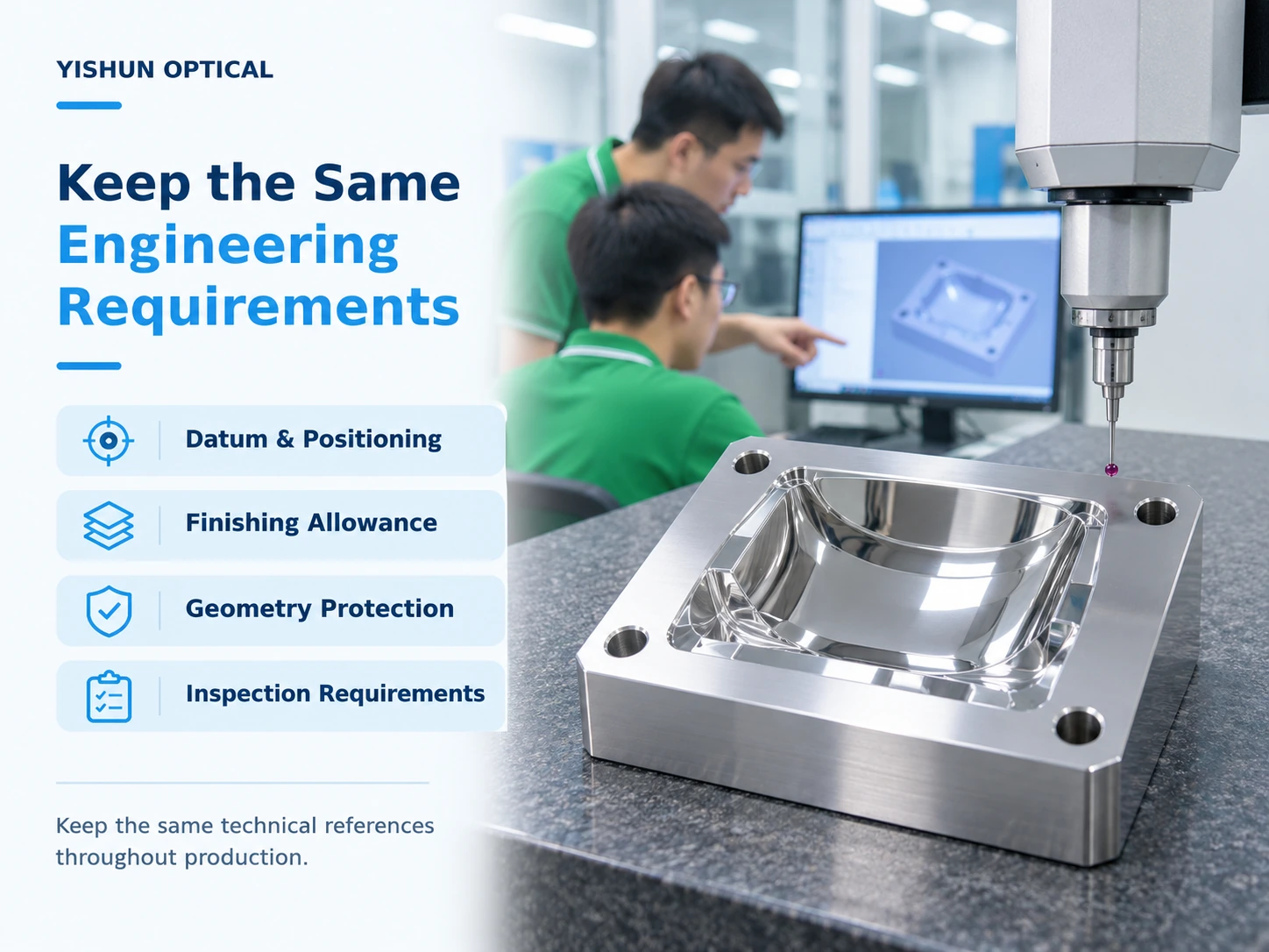
- The complex base geometry, cooling passages, alignment datum faces, and outer pockets are rough- and finish-machined on a 5-axis ultra-precision CNC milling center.
- The core blank is electroplated with electroless nickel-phosphorus on the optical active area.
- The optical prescription surface is diamond-turned on an SPDT lathe to achieve the final sub-nanometer mirror surface.
This hybrid approach capitalizes on the structural versatility of 5-axis CNC and the atomic-level surface quality of diamond turning.
Quality Assurance: Metrology Standards for Optical Mold Cores
Achieving sub-micron form accuracy and nanometer surface finishes requires rigorous metrology. When procuring high-precision optical mold cores, ensure your manufacturing partner verifies quality using specialized inspection equipment:
- Surface Roughness Verification: Measured using 3D Non-Contact White Light Interferometry (WLI) or Laser Confocal Microscopy. Standard stylus profilometers are generally too coarse and risk scratching delicate diamond-turned or nickel-plated surfaces.
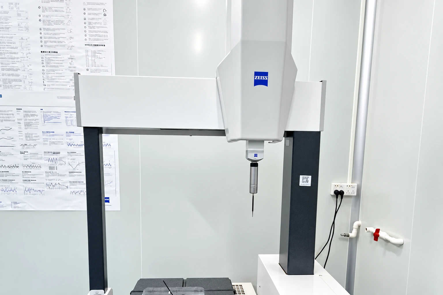
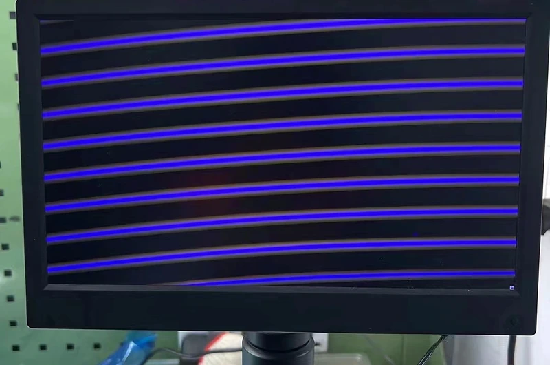
- Form Accuracy (PV / Power / Irregularity): Verified using Phase-Shifting Laser Interferometry for standard spheres and planar surfaces, or Ultra-Precision Coordinate Measuring Machines (CMM) and tactile profilometers (e.g., Taylor Hobson LuphoScan or Form Talysurf) for non-spherical and freeform optics.
- Surface Defect and Scratch-Dig Analysis: Inspected under calibrated optical magnification to confirm the absence of micro-voids in nickel plating, burrs along micro-edges, or chatter marks from milling vibration.
Partnering with an Ultra-Precision Machining Specialist
Balancing form accuracy, surface roughness, and production economics requires early collaboration between optical designers and machining specialists. Choosing between 5-axis ultra-precision milling and SPDT is rarely an either-or decision—it is a strategic choice driven by optical function, mold durability, and cost-efficient production.
Yishun provides comprehensive engineering support for complex optical mold projects, combining ultra-precision 5-axis milling and diamond turning capabilities to deliver mold cores tailored to your exact optical specifications.
Key Takeaways
- Cutting Mechanism: SPDT uses an atomically sharp diamond tool to generate sub-nanometer mirror finishes on non-ferrous metals and NiP coatings, completely eliminating manual post-polishing.
- Material Constraints: Diamond chemically reacts with the iron in standard hardened steels. Machining steel cores with SPDT requires an intermediate layer of electroless nickel plating (NiP).
- Geometric Flexibility: 5-axis ultra-precision CNC milling handles complex freeform optics, steep sidewalls, multi-cavity blocks, and micro-structures directly in hardened tool steels.
- Hybrid Manufacturing: Combining 5-axis CNC pre-machining with SPDT finish-turning on a nickel-plated layer provides an optimal balance of structural strength and optical surface quality.
- Metrology: Non-contact optical metrology (White Light Interferometry and laser profilometry) is required to inspect optical mold cores without damaging micro-machined surfaces.
FAQ
Can diamond turning be used directly on hardened stainless steel mold inserts?
No. Diamond tools wear rapidly when cutting ferrous metals due to chemical reactions and carbon diffusion at high cutting temperatures. To use SPDT on steel mold cores, the steel substrate must first be electroplated with a layer of electroless nickel-phosphorus (NiP), which can then be diamond-turned without premature tool degradation.
Does 5-axis ultra-precision CNC milling produce an optical mirror finish?
Ultra-precision 5-axis milling can achieve very low surface roughness ($Ra < 20\text{ to }50\text{ nm}$), which is suitable for many illumination, light-guide, and non-imaging optical applications. For high-precision visible-light imaging optics, milled surfaces often require specialized micro-polishing to remove microscopic milling cusp marks.
What is the primary advantage of Fast Tool Servo (FTS) in SPDT?
Fast Tool Servo (FTS) adds a high-frequency, piezo-driven linear axis to the diamond turning setup. This allows the diamond tool to oscillate rapidly in synchronization with spindle rotation, making it possible to cut non-rotationally symmetric freeforms, toric lenses, and off-axis segments on a lathe setup.
When is a hybrid manufacturing approach recommended?
A hybrid approach is recommended when an optical mold insert requires high mechanical strength, complex mounting datums, or integrated cooling channels in solid steel, combined with an optical surface that requires a sub-nanometer mirror finish. The base steel is machined on a multi-axis CNC, plated with electroless nickel, and finished using SPDT.