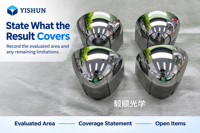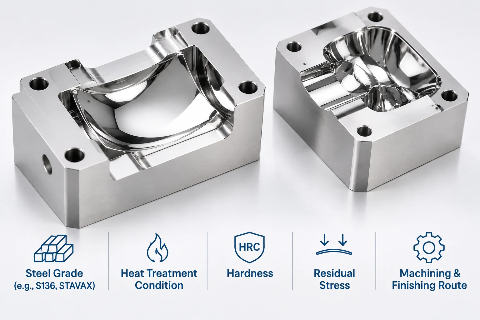
The inspection report shows an acceptable result. During review, the customer asks whether the narrow transition beside the optical surface was included.
The supplier points to the measured region. The customer points to a larger functional area on the drawing.
The disagreement is about the boundary of the evidence.
An optical mold insert inspection area should be defined clearly enough that both teams can identify what was evaluated, what was not evaluated and how the remaining requirements will be addressed.

Start With the Required Area
Before discussing measurement coverage, establish the region that must satisfy each requirement.
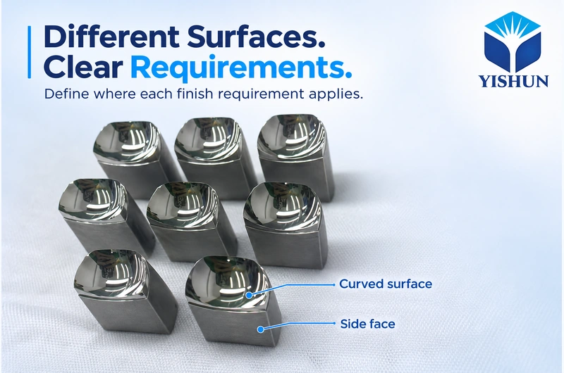
The functional optical area, the finished surface and the region accessible to a particular measurement setup may have different boundaries. Treating them as interchangeable can leave an acceptance gap.
Identify the required area from approved engineering information. For a curved or irregular insert, use a controlled drawing view or model reference that makes its location and orientation clear.
Do not define the acceptance region simply by copying the area that was easiest to measure. If the requested coverage cannot be achieved as planned, that is a question to resolve with the customer.
Make the Boundary Reproducible
A description such as “central area” may be understandable during a discussion but difficult to reproduce during inspection.
Define the boundary using references appropriate to the component. Depending on the geometry, these could include dimensions from agreed datums, a defined outline or an identified surface region in the approved model.
Record the drawing or model revision associated with that definition. Include orientation when similar-looking regions could be confused.
The objective is not to add unnecessary documentation. It is to allow another reviewer to locate the same area without relying on the memory of the person who performed the measurement.
Separate Planned Coverage From Actual Coverage
The inspection plan describes what the team intends to evaluate. The completed inspection record should describe what was actually evaluated.
These may differ.
A planned location may prove inaccessible. A measurement may not produce usable data across the expected region. A setup may cover most of the required surface while leaving a local gap.
Record these differences rather than presenting the planned boundary as proof of completed coverage.
A practical record can distinguish the required region, the area supported by valid measurement evidence and any unresolved area. Those distinctions should remain visible when the result is summarized.
Do Not Let a Blank Region Explain Itself
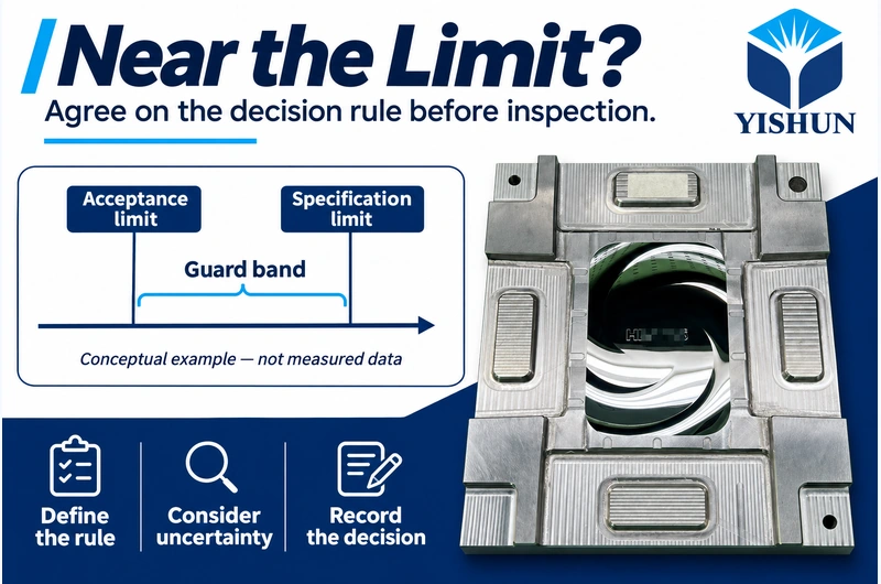
An empty area on a measurement image is ambiguous.
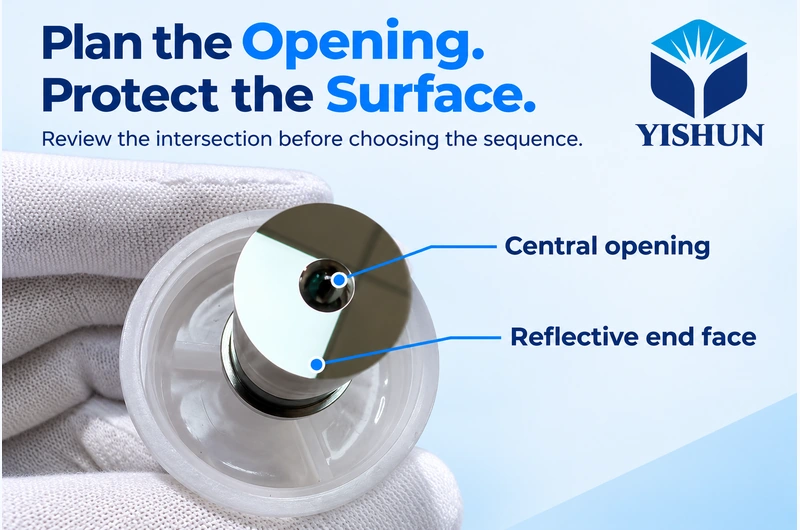
It could represent an opening in the component, a location outside the measurement field, unusable data or an intentionally excluded region. A reviewer should not have to guess which explanation applies.
Use clear notes or a coverage illustration to identify the reason. Where the meaning depends on the measurement system, explain the relevant display convention.
A blank region should not be interpreted as either an acceptable result or a defect without supporting information. Its first meaning is that the displayed result does not, by itself, describe that location.
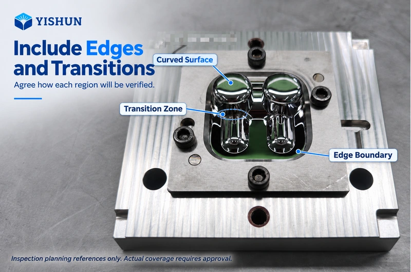
Give Edges and Transitions an Explicit Disposition
An edge or transition may fall outside one measurement result while still having a functional requirement.
The next question is what evidence will address it.
Depending on the project, the response may involve a different setup, another suitable verification method or a customer-approved acceptance arrangement. Confirm feasibility before promising coverage.
If a region remains unverified, record that limitation and obtain the required disposition before declaring the relevant requirement satisfied.
Avoid adopting an arbitrary edge exclusion simply because it is convenient. Any exclusion affecting acceptance needs an agreed basis; it is not automatically authorized by the limitations of one setup.
Keep Coverage Separate From the Numerical Result
A reported value answers a question within the conditions used to calculate it. The area included in the evaluation is one of those conditions.
If the evaluated region changes, the basis of comparison changes too. A result from a reduced area should not silently replace one obtained over a larger region.
Record the revised boundary and the reason for the change. Where applicable, retain the earlier result so reviewers can understand the relationship between the two evaluations.
This is especially important when comparing supplier and customer reports. Before treating different values as evidence of a manufacturing change, confirm that both evaluations address the same region.
Agree on Changes Before Closing Acceptance
Measurement difficulties can emerge after the inspection plan is approved. The response should be controlled without assuming that the original requirement has disappeared.
Explain the affected location, the coverage limitation and the proposed alternative. Identify whether the change affects only the measurement arrangement or also changes the acceptance scope.
These are different decisions.
A new setup may preserve the original requirement. Reducing the accepted area changes what the customer is being asked to approve.
During custom optical mold core and insert machining, coverage questions should therefore be considered alongside the geometry and agreed inspection scope. The manufacturing team should know which regions still require evidence before delivery.
Close the Report With a Clear Coverage Statement
A useful final statement identifies the area evaluated, the applicable requirement and any remaining limitation.
Avoid a broad “surface passed” conclusion when the evidence supports a narrower statement. Equally, do not imply that an unmeasured location has failed.
Before release, check that:
The required boundary is identifiable.
Actual coverage is recorded.
Unusable or excluded regions are explained.
Outstanding areas have an agreed disposition.
Any change to acceptance scope is approved.
When requesting a review, provide the approved surface boundary, relevant drawing or model, acceptance requirements and any existing coverage images. Highlight locations where measurement access or interpretation has already caused uncertainty.
Share these requirements with YISHUN Optical so the discussion can establish what must be verified and how the coverage will be documented.