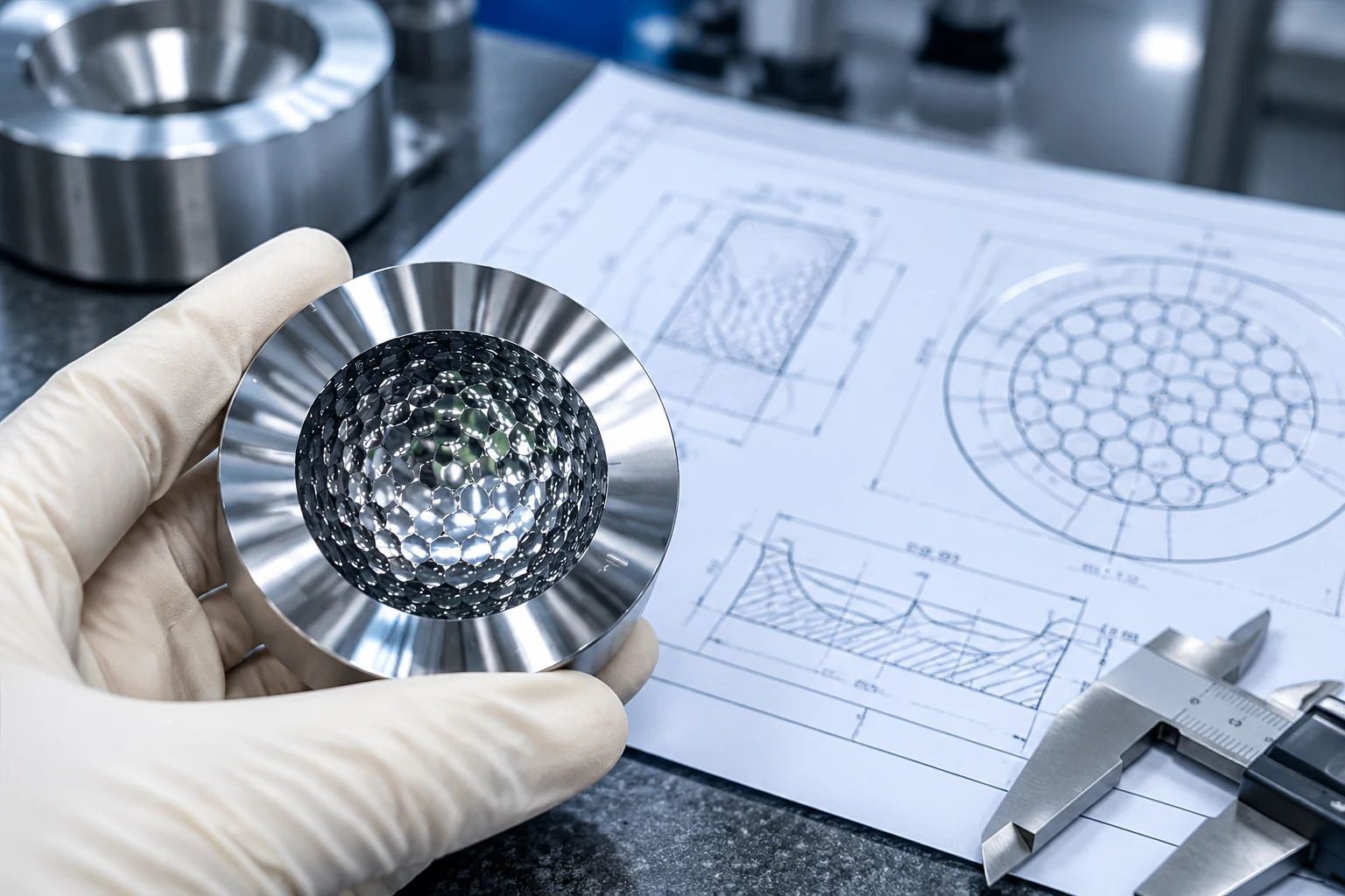
A supplier sends a surface measurement report. Later, a revised report shows a different roughness value for the same insert. No additional machining or polishing has taken place.
Has the surface changed, or has the evaluation changed?
Before requesting rework, identify what produced the difference. A roughness result describes a particular measurement evaluated in a particular way. The number alone does not explain which data were included or how they were processed.
For buyers reviewing optical mold inserts, this distinction can prevent an unnecessary finishing operation and help resolve disagreements using evidence.

Establish Whether the Reports Use the Same Measurement
“The same insert” does not necessarily mean “the same data.”
One report may come from a new scan, another location or a different field of view. Alternatively, both reports may have been calculated from one saved measurement.
Ask for the measurement identifier, acquisition date and location reference. Distinguish the time the surface was measured from the time the report was generated.
If the underlying acquisition differs, investigate those differences before attributing the change to software processing. If the acquisition is identical, compare the evaluation settings first.
This simple separation narrows the investigation without assuming either result is wrong.
Confirm That the Reported Quantity Is Comparable
Start with the parameter name and unit.
A profile parameter and an areal parameter do not describe the same dataset. Likewise, arithmetic-average and root-mean-square parameters use different calculations. Similar-looking labels or values do not make them interchangeable.
Check whether a revised report changed the reported quantity, extracted a profile from an area measurement or used a different evaluation region.
Do not convert one parameter into another using an assumed universal ratio.
If the drawing requires a particular parameter, acceptance should follow that requirement and the agreed method. A different available output may provide useful supplementary information, but it should not silently replace the specified result.
Examine Form Removal and Filtering
Surface height data may contain overall shape, longer-scale variation and finer texture. Processing helps separate the components relevant to the evaluation.
Removing tilt or a fitted shape changes the reference from which remaining heights are evaluated. Filtering changes which spatial scales contribute to the reported texture.
These operations can therefore change a numerical result without physically changing the part.
The appropriate settings depend on the measurement purpose and applicable specification. There is no single filter that should be applied to every mirror-finish insert.
Request the processing sequence, fitted form and filter settings used in each report. A statement such as “standard software settings” is not enough to reproduce the evaluation.
Check What Was Included or Excluded
A result can also change when the evaluation area changes.
A cropped region may omit an edge, include another surface or exclude a localized feature. A mask may remove points that the software could not measure reliably.
Such actions may be justified, but their purpose and effect should be visible.
Ask which regions were excluded and why. Distinguish missing or unreliable measurement data from actual surface features that remain subject to acceptance.
If a scratch is excluded from a texture calculation, that does not establish that the scratch is acceptable. It may still require a separate assessment.
Keep the reason for exclusion connected to the agreed evaluation method.
Review Corrections to the Data
Analysis software may offer functions for handling isolated points, filling gaps or correcting apparent acquisition artifacts.
Before comparing reports, establish whether any of these functions were used and whether their settings changed.
An apparently unusual point could be a measurement problem, contamination or a physical feature. Its appearance in the dataset does not determine which explanation is correct.
Where the distinction matters, review the original data and, if appropriate, inspect or measure the surface again.
Preserve the original acquisition rather than retaining only a processed export. Otherwise, the team may be unable to determine whether the revised value reflects a justified correction or a change that removed relevant information.
Compare Evaluations Before Comparing Suppliers
When two parties report different values, avoid immediately ranking their instruments or machining quality.
First compare the parameter, units, measurement location, field of view, processing sequence and exclusion rules. Identify which differences are known and which remain unresolved.
If compatible data are available, applying an agreed evaluation recipe can help isolate the effect of processing. It does not eliminate differences in acquisition or prove that either instrument is suitable for every requirement.
The objective is a comparison with a defined scope, not a search for the smallest number.
Keep the Acceptance Method Stable
Once the parties agree on an evaluation method, record enough detail to apply it consistently.
A saved recipe can help, but it should be identifiable and linked to the relevant drawing or inspection instruction. Changes need a reason and a record of their effect.
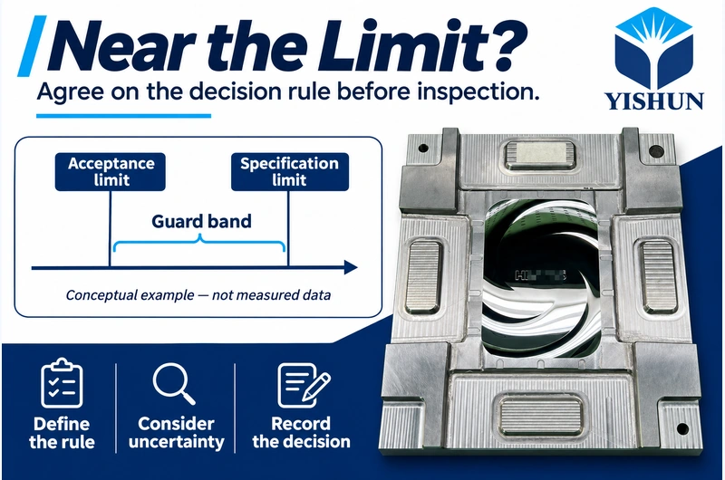
Do not choose new settings simply because the original result is close to an acceptance limit. If the original method was unsuitable, document the correction and decide how earlier results will be treated.
For repeat orders, retain the agreed method with the project records so a new operator does not unknowingly introduce another interpretation.
Resolve the Difference Before Removing Material
A revised roughness value is a reason to investigate, not automatic evidence that the insert needs more polishing.
Before approving rework, establish whether the actual surface fails an applicable requirement under the agreed evaluation method. Keep appearance, local defects and form requirements separate where they require different evidence.
For custom optical mold inserts, five-axis precision machining is one possible manufacturing route; the inspection result must still be interpreted within its stated scope.
YISHUN Optical supports mirror-finish mold insert customization and ultra-precision component machining. To review conflicting reports, provide both versions, the specified parameter, measurement references and available processing settings.
The first decision is whether the evidence changed—not whether more material should be removed.