Key Takeaways
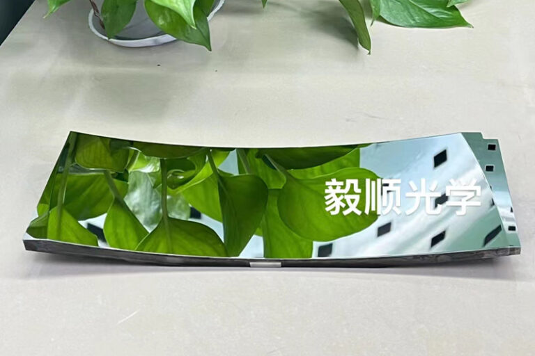
- AR head-up displays require surface accuracies exceeding 0.5 waves PV to ensure image clarity and driver safety
- Combiner optical elements demand Ra <1nm surface roughness to eliminate ghost images and distortion
- Aspheric and freeform surfaces require multi-axis precision machining with ±0.5μm tolerance control
- HUD picture generation units employ precision-machined mirrors with ultra-smooth reflective coatings
- Material selection balances thermal stability, weight, and machinability for automotive environments
- YISHUN Optical’s diamond turning expertise supports next-generation AR HUD development
Augmented Reality Head-Up Display (AR HUD) systems represent one of the most demanding applications for automotive optical manufacturing. Unlike conventional HUDs that project simple warning indicators onto the windshield, AR HUD systems overlay navigation prompts, lane guidance, and object markers directly onto the driver’s view of the road—requiring optical precision that matches or exceeds other ADAS perception systems.
For optical engineers and procurement professionals involved in automotive HUD development, understanding the manufacturing challenges and quality requirements is essential for successful program execution.
The Evolution of Automotive HUD Technology
Head-up displays have evolved through distinct generations, each imposing different requirements on optical component manufacturing.
First Generation: Conventional HUDs
Early automotive HUDs projected monochrome information onto a small combiner area, displaying speed, navigation turn-by-turn directions, and basic warnings. These systems employed simple spherical mirrors and required limited optical precision. Manufacturing focused on replication processes like injection molding with moderate surface quality specifications.
Second Generation: Full-Color TFT HUDs
Color thin-film transistor displays enabled richer information presentation, including navigation graphics and enhanced warning symbols. Optical requirements increased to include larger fields of view, improved brightness, and reduced image distortion. Aspheric mirrors became standard, with surface accuracies measured in waves rather than micrometers.
Third Generation: AR Augmented Reality HUDs
Current AR HUD systems represent a fundamental advancement in capability and complexity. These systems must:
- Display information at apparent distances from 7 meters to infinity
- Overlay virtual objects precisely aligned with real-world features
- Maintain alignment accuracy under vehicle vibration and thermal extremes
- Present information across fields of view exceeding 10° horizontal
- Support both near-field and far-field content simultaneously
Meeting these requirements demands optical precision that rivals semiconductor lithography systems rather than traditional automotive manufacturing.
Critical Optical Components in AR HUD Systems
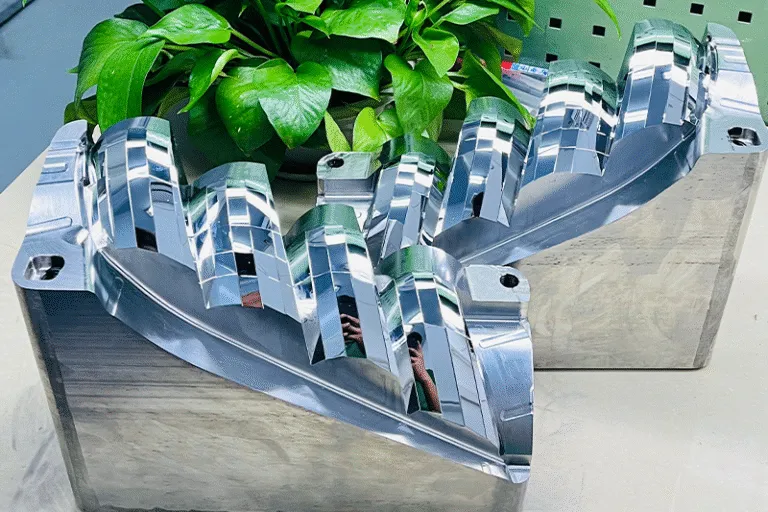
AR HUD systems comprise several precision optical elements, each with specific manufacturing requirements.
Combiner Optical Elements
The windshield or dedicated combiner must act as a partial reflector while remaining transparent. Surface flatness and absence of defects are critical—any surface irregularity creates visible artifacts in the projected image. Manufacturing specifications typically require:
- Surface accuracy: λ/2 or better PV at 632.8nm
- Surface roughness: Ra <1nm for coating-ready surfaces
- Local slope errors: <30 arc-seconds
These specifications eliminate visible ghost images, fringing, and distortion that would distract drivers and compromise system utility.
Aspheric and Freeform Mirrors
AR HUD systems employ sophisticated mirror geometries that correct for windshield distortion, expand field of view, and project images at appropriate virtual distances. Unlike simple spherical mirrors, these elements require:
- Complex surface descriptions defined by mathematical functions
- Manufacturing accuracy measured in micrometers across full apertures
- Verification using coordinate measuring systems and optical profilometry
- Diamond turning or specialized grinding followed by computer-controlled polishing
The mirror substrate must also maintain dimensional stability across the automotive temperature range, requiring careful material selection and stress management during manufacturing.
Picture Generation Unit Optics
The image source typically employs LED or laser illumination focused through precision microlens arrays or waveguide structures. These miniature optical elements require sub-micron positioning accuracy during assembly and surface qualities matching the combiner specifications.
Manufacturing Technologies for HUD Optical Components
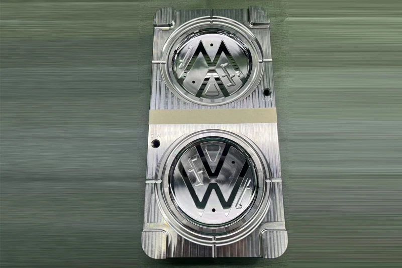
Producing AR HUD optical elements meeting these demanding specifications requires advanced manufacturing capabilities.
Single Point Diamond Turning (SPDT)
Diamond turning has become essential for HUD mirror manufacturing. The Moore Nanocenter and similar systems can produce aspheric and freeform surfaces with:
- Form accuracies to 0.5μm PV across full aperture
- Surface roughness below Ra 1nm directly from the machine
- Tool paths calculated from optical surface definitions
- No requirement for manual polishing in many cases
The single-point diamond cutting tool maintains its edge geometry through hundreds of cutting operations, ensuring consistency across production volumes.
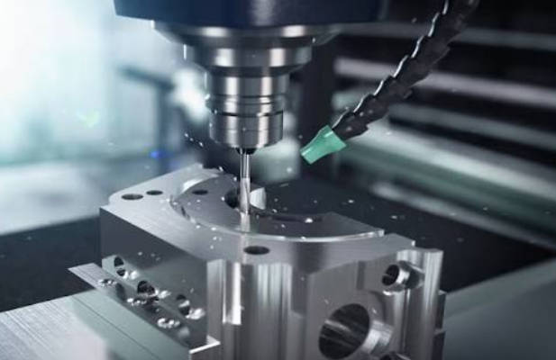
Multi-Axis Precision Machining
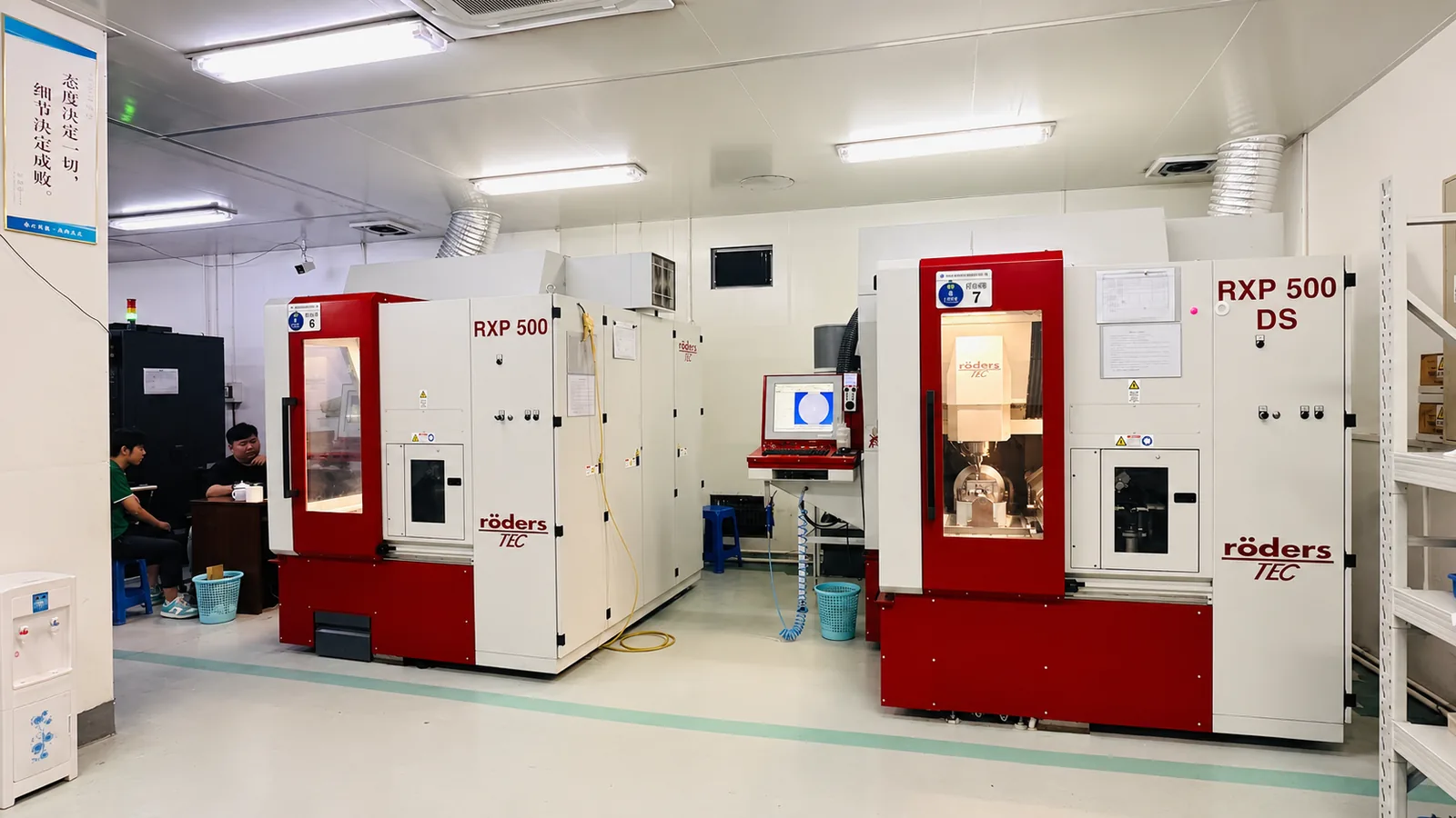
Complex HUD optical elements may require five-axis machining centers to produce all necessary features in a single setup. RODERS five-axis machining centers provide:
- Simultaneous positioning of rotary and linear axes
- Intricate surface geometries with continuous tool paths
- Integrated probing for in-process verification
- Consistent accuracy across large production batches
Material Considerations for HUD Optical Manufacturing
Material selection for HUD optical components balances multiple factors including optical performance, thermal behavior, weight, and manufacturing process compatibility.
| Material | Advantages | Manufacturing Considerations |
|---|---|---|
| Aluminum 6061/7075 | Excellent machinability, thermal stability | Diamond turnable, coating compatible |
| Optical PMMA | High optical clarity, light weight | Brittle, sensitive to machining heat |
| Polycarbonate | Impact resistant, durable | Birefringence concerns, careful parameters |
| Optical Glass | Superior optical properties | Requires grinding and polishing, not diamond turnable |
| Molded Glass | Cost-effective for volume | Tooling investment, design constraints |
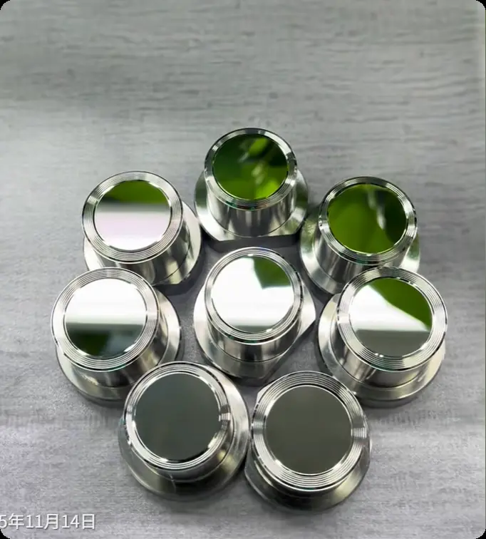
Most diamond-turned HUD mirrors use aluminum alloys that can be machined to optical quality and subsequently coated with reflective treatments. The machinability of aluminum enables complex surface geometries while maintaining the precision required for AR display performance.
Surface Quality and Coating Compatibility
AR HUD mirror performance depends critically on the quality of reflective coatings applied to the optical surfaces. These coatings must:
- Provide high reflectance across visible wavelengths
- Maintain performance across automotive temperature range
- Resist degradation from UV exposure and humidity
- Adhere properly to the substrate surface
Coating compatibility requires surface preparation meeting strict specifications. Surface roughness must be low enough to support uniform coating deposition, typically Ra <1nm. Surface chemistry must ensure proper coating adhesion, and surface contamination must be eliminated before coating.
The manufacturing process must therefore produce surfaces that are immediately coating-ready without additional processing steps. Diamond turning achieves this directly, while traditional grinding and polishing may require additional preparation.
Tolerance Analysis for AR HUD Systems
AR HUD systems exhibit tight error budgets that flow down to individual component specifications. Understanding these relationships enables appropriate tolerance allocation.
Virtual Image Positioning
AR HUD systems display information at specific virtual distances to match driver accommodation and provide intuitive guidance. Virtual image distance depends on:
- Combiner surface geometry
- Mirror focal lengths and positions
- Image source location
- Assembly alignment
Small errors in any element can shift the apparent image position by meters, defeating the purpose of augmented reality overlay.
Distortion Control
Combiner surface irregularities translate directly into image distortion visible to drivers. This distortion is particularly problematic for AR applications where virtual objects must appear aligned with real-world features. Surface figure specifications of λ/2 PV or better ensure distortion remains below perceptible levels.
Eye Motion Box Optimization
The eye motion box defines the region where drivers can view the full HUD image without clipping. Optical element positioning tolerances determine the size and location of this viewing zone. Manufacturing variations that shift element positions reduce the effective eye motion box, potentially blocking portions of the display for some drivers.
Quality Verification for HUD Optical Components
Verifying that manufactured components meet AR HUD specifications requires advanced metrology systems.
Interferometric Surface Testing
Zygo interferometers and similar systems measure surface figure with nanometer-level resolution. Testing at multiple wavelengths and orientations reveals surface errors that might otherwise escape detection.
Optical Profilometry
White-light interferometers and confocal profilometers map surface topography across full apertures, identifying local surface irregularities that could create visible artifacts.
Coordinate Metrology
High-precision coordinate measuring machines verify dimensional characteristics including mounting features, clearances, and relationship between optical surfaces.
Environmental Testing
Components should survive thermal cycling, humidity exposure, and vibration testing that simulates automotive service conditions. Testing after environmental exposure verifies that coatings and substrates remain stable.
Design Considerations for Manufacturable HUD Optics
Successful AR HUD development requires design practices that consider manufacturing realities.
Feature Accessibility
Diamond turning tools require clearance for approach and withdrawal that constrains achievable surface geometries. Designers should consult with manufacturing engineers early to identify potential tool clearance issues.
Datum References
Optical performance depends on relationships between surfaces that must be measured during manufacturing and maintained during assembly. Accessible datum features enable precise metrology and consistent assembly.
Tolerancing Strategy
Optical tolerances must balance manufacturing capability with system-level performance requirements. Overly tight tolerances increase cost without improving system performance, while insufficient tolerances compromise image quality.
Future Directions in AR HUD Optical Manufacturing
AR HUD technology continues advancing, with manufacturing requirements evolving accordingly.
Larger Fields of View
Next-generation systems will require fields of view exceeding 15° horizontal to provide more comprehensive information presentation. Larger optical elements with maintained precision challenge manufacturing capability.
Extended Virtual Distances
Displaying AR content at distances beyond 20 meters requires corresponding optical system expansion. This translates into larger mirrors and more demanding surface accuracy requirements.
Waveguide Integration
Emerging waveguide-based HUD systems replace conventional mirror optics with diffractive elements. These components require entirely different manufacturing approaches including nano-imprint lithography and specialized coating processes.
Cost Reduction Pressure
As HUD systems transition from premium to mainstream vehicles, cost pressure intensifies. Manufacturing processes must improve efficiency while maintaining precision, driving adoption of automation and optimized workflows.
Conclusion
AR head-up displays represent a convergence of automotive safety requirements and optical engineering precision. Manufacturing these systems requires capabilities that push the boundaries of precision manufacturing, including sub-nanometer surface quality, micrometer-level tolerances, and comprehensive quality verification systems.
The complexity of AR HUD optical systems demands close collaboration between optical designers and manufacturing engineers from the earliest stages of program development. Designs must be optimized for both optical performance and manufacturing reality, with clear communication of requirements and capabilities throughout the development process.
Frequently Asked Questions
What surface roughness is required for AR HUD combiner elements?
AR HUD combiner elements typically require surface roughness below Ra 1nm to support high-quality reflective coatings and eliminate visible surface artifacts in the projected image.
Can diamond-turned aluminum mirrors meet HUD optical specifications?
Yes, diamond-turned aluminum mirrors can achieve surface accuracies of 0.5 waves PV and roughness below Ra 1nm, meeting most HUD optical requirements directly from the turning operation.
How does temperature affect HUD mirror performance?
Thermal expansion can shift optical element positions and alter surface geometries. Manufacturing processes must control residual stress, and material selection must account for thermal behavior to ensure consistent performance across the automotive temperature range.
What materials are used for AR HUD optical elements?
Common materials include aluminum alloys for mirrors, optical PMMA or polycarbonate for combiners, and specialized optical glasses for waveguide elements. Material selection depends on optical requirements, weight constraints, and manufacturing process compatibility.
How are freeform HUD mirrors manufactured?
Freeform mirrors are typically manufactured using diamond turning on multi-axis machining centers. The mathematically-defined surface is converted to tool paths that guide the diamond tool through the required contour.
What quality verification methods are used for HUD optical components?
Verification employs interferometric testing, optical profilometry, coordinate metrology, and environmental testing to confirm that components meet surface accuracy, roughness, and stability requirements.
How do AR HUD tolerances compare to conventional HUD systems?
AR HUD systems require significantly tighter tolerances than conventional systems due to the precision required for augmented reality overlay. Tolerances of ±0.5μm are common for critical positioning dimensions.
Interested in discussing your AR HUD optical component requirements? Contact YISHUN Optical at info@yishunoptical.com or visit yishunoptical.com to explore how our ultra-precision manufacturing capabilities can support your next-generation head-up display development.