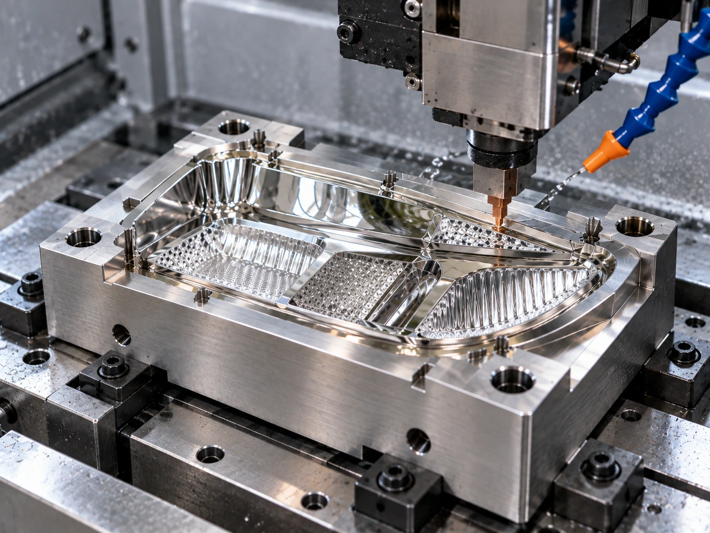
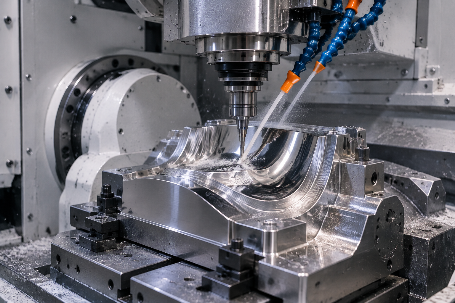
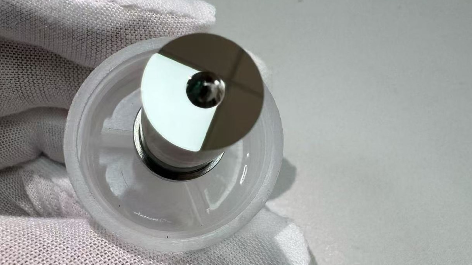
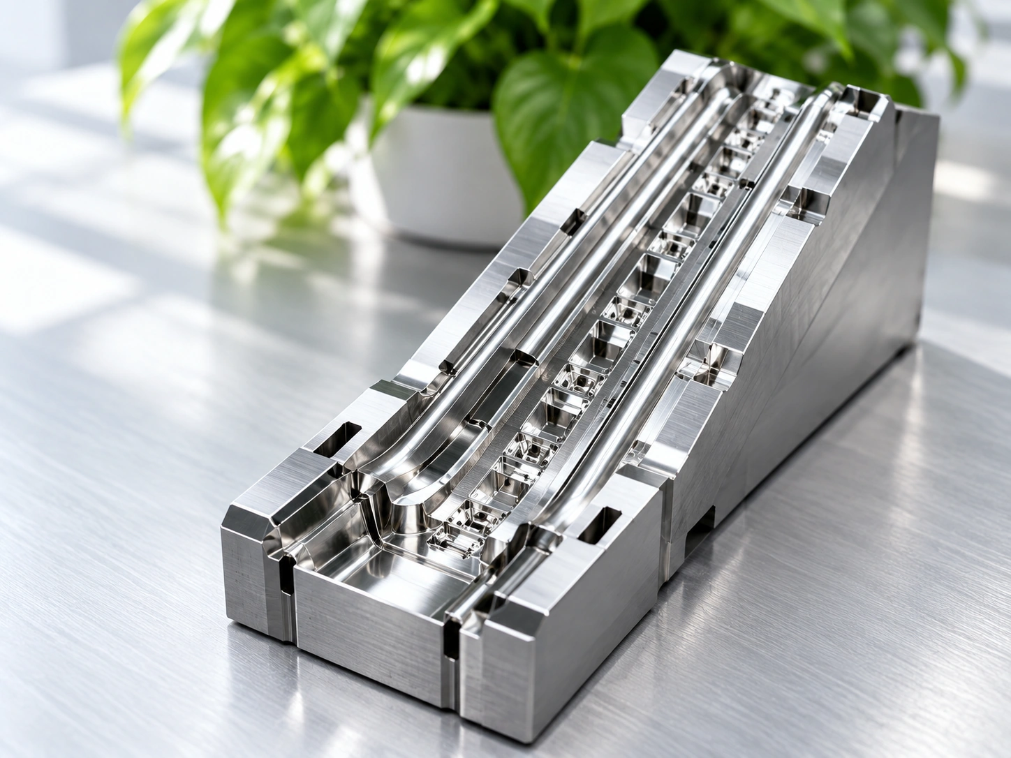
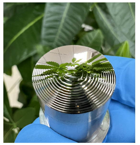
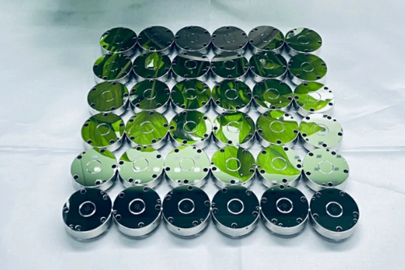
Ultra precision machining achieves tight tolerances and fine surface finishes by controlling not one variable, but an entire chain of potential errors.
Machine motion accuracy, spindle behavior, cutting tools, fixturing, thermal stability, vibration, material response, process parameters, and metrology all contribute to the finished component.
Ultra precision machining tolerance is ultimately the result of controlling the total error budget of the manufacturing process, not simply using a machine with a very small positioning increment.
This distinction is critical.
A machine controller may command extremely small movements, but the finished part can still fall outside specification if the workpiece expands from temperature, the fixture distorts the component, the tool wears, or the measurement system cannot resolve the actual error.
For engineers and buyers, understanding this error chain makes it easier to specify realistic tolerances and evaluate whether a machining supplier can maintain them consistently.
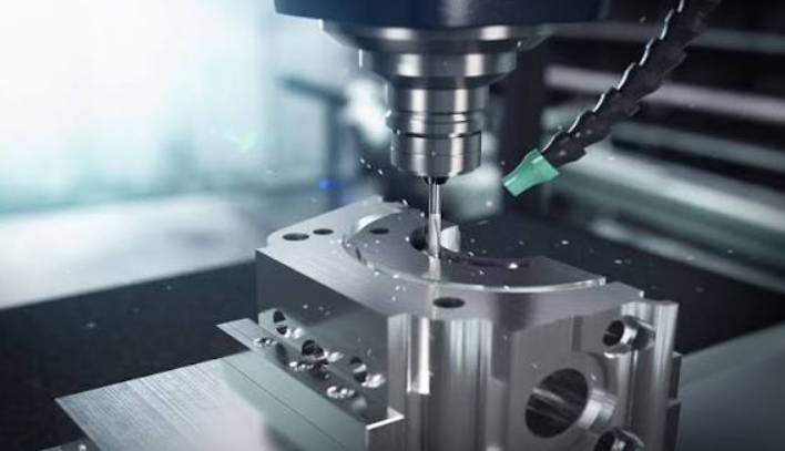
Tight Tolerance Machining Is an Error-Budget Problem
Every manufacturing process contains error.
In conventional machining, many of these errors are small compared with the drawing tolerance.
In ultra precision machining, they can become significant.
Consider a component with a very tight dimensional or form requirement.
Potential sources of error include:
- Linear-axis positioning error;
- Spindle error motion;
- Machine geometry;
- Tool-setting error;
- Tool wear;
- Fixture deformation;
- Workpiece deformation;
- Thermal expansion;
- Cutting forces;
- Vibration;
- Material instability;
- Measurement uncertainty.
Each source may contribute only a small amount.
Together, however, they can determine whether the finished part passes or fails.
The closer the required tolerance approaches the scale of the process errors, the more important machine stability, environmental control, metrology, and compensation become.
This is why ultra precision machining should be considered a controlled manufacturing system rather than simply a more accurate version of conventional CNC machining.
1. Machine Motion Must Be More Accurate Than the Required Part
The first foundation is machine-tool accuracy.
A machining system must move the cutting tool and workpiece along a predictable path.
This requires control of:
- Linear positioning;
- Straightness;
- Axis squareness;
- Rotary positioning;
- Spindle error motion;
- Axis synchronization;
- Repeatability.
For complex surfaces, multiple axes may need to move simultaneously while maintaining the programmed relationship.
Any deviation becomes part of the manufactured surface.
Resolution Is Not the Same as Accuracy
This is an important distinction.
A control system may have an extremely small programmed movement increment.
That does not automatically mean the machine can produce a part to the same tolerance.
For example, a system capable of commanding a tiny axis movement may still experience:
- Mechanical error;
- Temperature drift;
- Servo following error;
- Tool-position uncertainty;
- Spindle motion error.
Machine resolution describes how finely movement can be commanded.
Part accuracy describes how closely the final component matches the intended geometry.
These are related but not identical.
2. Thermal Stability Becomes a Dimensional Requirement
Temperature is one of the most important variables in tight tolerance machining.
Most engineering materials expand when temperature rises and contract when temperature falls.
The amount may appear insignificant during conventional machining.
At micron and sub-micron scales, it can become large enough to affect the result.
Thermal changes can occur in:
- The workpiece;
- Spindle;
- Machine structure;
- Cutting tool;
- Fixture;
- Measurement system.
Sources include:
- Spindle operation;
- Motors;
- Cutting heat;
- Coolant temperature;
- Room-temperature variation;
- Operator handling.
For this reason, ultra precision machining systems often emphasize thermal equilibrium and controlled machining conditions.
Why Stabilization Before Machining Matters
Imagine machining a component immediately after it enters a controlled room from a warmer environment.
The part may slowly contract while machining continues.
Even if every commanded tool movement is correct, the physical dimensions of the workpiece are changing during the operation.
A similar problem occurs when a spindle gradually warms during operation.
When tolerances become extremely tight, temperature is no longer just an environmental condition—it becomes part of the dimensional control strategy.
3. Tool Geometry Directly Becomes Surface Geometry
In ultra precision machining, the cutting tool is not simply removing material.
Its geometry may be transferred directly into the surface.
Factors include:
- Cutting-edge sharpness;
- Tool radius;
- Tool profile;
- Tool position;
- Tool wear;
- Edge defects.
For single-point processes, an inaccurate tool radius or incorrectly located cutting edge can create systematic form errors.
For milling and grinding, tool runout and abrasive condition also affect the generated surface.
Tool Wear Is Particularly Important
A tool does not remain identical throughout production.
Wear can gradually change:
- Cutting forces;
- Effective tool geometry;
- Surface roughness;
- Burr formation;
- Dimensional accuracy.
This creates an important production question:
Can the process remain inside tolerance throughout the complete batch?
A prototype produced with a fresh tool does not automatically prove that the same result can be maintained across repeat production.
Tool-life monitoring and controlled replacement strategies therefore become part of the precision process.
4. Fixturing Can Introduce Errors Before Cutting Begins
Even an exceptionally accurate machine cannot produce an accurate free-state component if the workpiece is distorted by the fixture.
Consider a thin precision component.
If excessive clamping pressure bends the part slightly, machining may produce a perfectly accurate surface while the component remains clamped.
After removal:
- Clamping force disappears;
- The component relaxes;
- The original elastic deformation changes;
- The finished geometry shifts.
The component may then fail inspection.
Precision Fixturing Must Control More Than Position
A fixture should consider:
- Datum location;
- Clamping force;
- Support distribution;
- Workpiece stiffness;
- Accessibility;
- Repeatability;
- Thermal behavior;
- Removal and reinstallation.
For delicate parts, options such as carefully distributed support or appropriate vacuum workholding may be evaluated.
Ultra precision fixturing must locate the component accurately without creating deformation larger than the allowed tolerance.
This is one reason complex thin-wall parts can be more difficult than thicker components even when their nominal dimensions are similar.
5. Cutting Forces Must Remain Predictable
Machining creates force.
That force can cause temporary deflection in:
- The cutting tool;
- Workpiece;
- Fixture;
- Spindle;
- Machine structure.
In conventional machining, these deflections may be small compared with the tolerance.
At ultra precision scales, they can matter.
Engineers therefore control variables such as:
- Depth of cut;
- Feed;
- Cutting speed;
- Tool geometry;
- Material-removal rate.
Finishing passes usually remove smaller amounts of material because reducing cutting forces can reduce deformation and improve final control.
However, simply using the smallest possible depth of cut is not always ideal.
Material behavior must remain stable enough for clean and predictable removal.
6. Vibration Directly Appears in the Surface
Vibration is another major source of surface error.
Possible sources include:
- Spindle imbalance;
- Machine drives;
- Pumps;
- Nearby machinery;
- Building vibration;
- Tool-workpiece interaction.
If vibration reaches the cutting interface, it can create repeating surface patterns.
Typical effects include:
- Chatter;
- Periodic marks;
- Waviness;
- Higher roughness;
- Form errors.
This is why ultra precision machine design frequently emphasizes:
- Stiff machine structures;
- High damping;
- Stable foundations;
- Controlled spindle motion;
- Vibration isolation.
A fine surface finish depends on the cutting edge following the desired surface path without unwanted motion.
7. Surface Finish Depends on More Than Dimensional Accuracy
Tight tolerance and fine surface finish are often discussed together, but they are different specifications.
Dimensional Tolerance
Controls characteristics such as:
- Diameter;
- Thickness;
- Position;
- Distance;
- Feature size.
Form Accuracy
Controls how closely a surface matches the intended geometry.
Examples include:
- Flatness;
- Roundness;
- Profile;
- Aspheric form.
Surface Roughness
Describes microscopic surface texture.
A component can therefore have:
- Excellent dimensions but poor roughness;
- Excellent roughness but unacceptable form;
- Accurate form but incorrect thickness.
A part is not automatically “ultra precise” because one measured parameter is extremely good; all functionally critical specifications must be controlled together.
What Controls Fine Surface Finish?
Fine surface finish depends on several interacting variables.
| Variable | Influence on Surface Finish |
| Tool sharpness | Worn or damaged edges increase surface defects |
| Tool geometry | Controls generated texture and cutting behavior |
| Feed rate | Can influence spacing of machining marks |
| Depth of cut | Affects forces and material response |
| Spindle motion | Error motion can appear as surface structure |
| Vibration | Produces chatter, waviness or periodic marks |
| Material microstructure | Can create non-uniform material removal |
| Thermal stability | Can alter tool-workpiece relationship |
| Coolant / process fluid | Influences heat, debris removal and surface condition |
| Tool wear | Can progressively degrade finish |
A low Ra value therefore does not come from one machine setting.
It results from maintaining the complete process in a stable operating window.
8. Material Behavior Changes the Achievable Result
Different materials do not machine the same way.
Important material characteristics include:
- Hardness;
- Elastic modulus;
- Grain structure;
- Brittleness;
- Thermal expansion;
- Chemical behavior;
- Internal stress.
A material that cuts cleanly may produce a very smooth directly machined surface.
Another material may require grinding or subsequent polishing.
This is why a supplier should never evaluate an ultra precision machining tolerance without knowing the exact material.
“Aluminum,” “plastic,” or “ceramic” may be too broad.
Exact grade and condition matter.
YISHUN Optical’s ultra precision machining services cover multiple machining approaches for different materials, geometries, and final surface requirements.
9. One Setup Can Reduce Accumulated Error
Every time a component is removed and repositioned, another source of uncertainty enters the process.
Repeated setups can introduce:
- Datum error;
- Angular error;
- Position shift;
- Fixture variation;
- Contamination between reference surfaces.
For this reason, performing multiple operations in one controlled setup can be valuable when geometry permits.
Consider two routes.
Route A
Machine Surface A
→ Remove Part
→ Refixture
→ Machine Surface B
Route B
Machine Surface A
→ Reorient Within Controlled Multi-Axis Setup
→ Machine Surface B
Route B can reduce the number of independent reference changes.
However, one-setup machining is not automatically better for every component.
Tool accessibility, stability, cycle time, and inspection requirements still need consideration.
10. Metrology Turns Machining into a Closed Feedback Loop
Measurement is not simply the final quality-control step in ultra precision manufacturing.
It can become part of the machining process itself.
A controlled process may look like:
Machine
↓
Measure
↓
Compare With Nominal Geometry
↓
Generate Error Map
↓
Compensate Tool Path
↓
Machine Again
↓
Verify
This is especially useful when extremely small repeatable errors remain after the first machining cycle.
Error Compensation
Suppose measurement shows that one region of a surface is consistently slightly above the nominal geometry.
If the error is repeatable and measurable, the tool path may be adjusted to compensate.
This changes precision manufacturing from:
“Cut and hope the machine is accurate enough”
into:
“Cut, measure, understand the error, compensate, and verify.”
Metrology is therefore part of the manufacturing process itself when tolerances become too tight to rely on machine positioning alone.
YISHUN Optical’s published ultra precision machining capabilities include dimensional and optical metrology using systems such as interferometers, profilometers, coordinate measurement equipment, and surface-roughness inspection.
Why On-Machine and Off-Machine Measurement Both Matter
On-machine measurement has one major advantage:
The component can remain in the same setup.
This reduces repositioning error and can accelerate compensation.
However, an important limitation exists.
If the same machine motion contributes to both machining and measurement, some machine-related errors may be difficult to detect independently.
Off-machine metrology provides a separate measurement system.
Therefore, demanding processes may use a combination of:
- On-machine process measurement;
- Independent dimensional inspection;
- Surface-form measurement;
- Roughness measurement;
- Final acceptance testing.
The correct combination depends on the drawing and application.
What Does YISHUN Optical Publish for Ultra Precision Machining?
According to YISHUN Optical’s published service information, its ultra precision machining capabilities include:
- Ultra precision turning;
- Ultra precision milling;
- Ultra precision grinding;
- Multi-axis machining;
- Precision surface finishing;
- In-process and final inspection.
Its published ultra precision turning capability lists:
- Surface roughness down to Ra 1 nm;
- Form accuracy controlled to approximately 0.1 μm for suitable projects;
- Dimensional tolerances down to ±0.5 μm for suitable applications.
These figures should not be interpreted as universal values for every component.
Actual capability depends on:
- Material;
- Geometry;
- Feature size;
- Component dimensions;
- Measurement method;
- Fixture strategy;
- Surface requirement;
- Production quantity.
Engineers should therefore submit drawings for project-specific evaluation rather than assuming that a headline tolerance applies equally to every feature.
Tight Tolerances and Fine Surface Finish Do Not Cost the Same
A common purchasing assumption is that changing a tolerance from:
±5 μm
to:
±1 μm
to:
±0.5 μm
simply requires entering a smaller number into the machine program.
It does not.
Tighter requirements may require:
- More stable equipment;
- Additional finishing passes;
- Longer thermal stabilization;
- Lower material-removal rates;
- More frequent measurement;
- Tool replacement;
- Custom fixtures;
- Environmental control;
- Compensation cycles;
- Higher inspection effort.
The manufacturing cost can therefore rise disproportionately as the required tolerance approaches the stable capability limit of the process.
How to Avoid Over-Specifying Precision
Not every surface and dimension needs the tightest possible tolerance.
Engineering drawings should separate:
Function-Critical Features
These directly affect:
- Optical performance;
- Alignment;
- Assembly;
- Motion;
- Sealing;
- Positioning.
Non-Critical Features
These may tolerate wider manufacturing variation without affecting performance.
Applying the same ultra-tight tolerance everywhere increases:
- Machine time;
- Inspection time;
- Rejection risk;
- Cost.
A better approach is to identify critical characteristics and allocate tolerance according to function.
Supplier Capability vs Machine Specification
One of the most important purchasing lessons is:
A machine specification is not the same as a demonstrated production capability.
When evaluating a tight tolerance machining supplier, ask:
- Has the supplier processed similar materials?
- Has it manufactured similar geometry?
- What tolerance can be maintained on this specific feature?
- What roughness can be measured reliably?
- How is thermal stability controlled?
- How is the part fixtured?
- How is tool wear monitored?
- Which measurements are performed during machining?
- Which measurements are performed independently?
- Can inspection reports be provided?
- How is repeat production controlled?
The supplier should be able to explain the complete process chain.
Simply stating that a machine has nanometer-level resolution is not sufficient.
Practical Tight Tolerance Machining Checklist
| Area | What Buyers Should Verify |
| Machine | Accuracy, repeatability and stability |
| Spindle | Low error motion and thermal control |
| Tool | Correct material, geometry and wear control |
| Fixture | Stable location without excessive distortion |
| Environment | Temperature and vibration control |
| Process | Stable cutting parameters and finishing strategy |
| Material | Exact grade and machining behavior |
| Metrology | Suitable measurement resolution and uncertainty |
| Compensation | Ability to correct repeatable process errors |
| Quality control | In-process and final documentation |
| Production | Repeatability across multiple batches |
What Should Be Included in an Ultra Precision Machining RFQ?
A complete RFQ should provide:
- 2D drawing;
- 3D model when relevant;
- Material and exact grade;
- Overall dimensions;
- Critical tolerances;
- Surface roughness;
- Flatness or form accuracy;
- Parallelism where relevant;
- Critical datum relationships;
- Quantity;
- Prototype quantity;
- Repeat-production quantity;
- Incoming material condition;
- Required inspection method;
- Required inspection report.
Avoid simply writing:
Highest possible precision required.
Instead, define measurable requirements.
For example:
Critical Surface A: drawing tolerance applies
Surface roughness: per drawing
Non-critical external dimensions: general tolerance applies
This gives the process engineer room to focus manufacturing effort where it actually matters.
How to Evaluate an Ultra Precision Machining Supplier
A capable supplier should connect five things:
Drawing → Process → Fixture → Metrology → Verification
If any link is missing, the claimed tolerance should be examined more carefully.
For example:
A supplier may claim it can hold an extremely tight dimension.
The next question should be:
How will you measure it?
If the available measurement uncertainty is too large relative to the tolerance, reliable acceptance becomes difficult.
Likewise:
How will the component be held?
If the fixture creates more deformation than the allowable form error, machine positioning accuracy alone cannot solve the problem.
YISHUN Optical provides custom ultra precision machining services covering turning, milling, grinding, surface finishing, and precision inspection for customized components.
Additional company and manufacturing information is available through the YISHUN Optical website.
FAQ
What is ultra precision machining tolerance?
Ultra precision machining tolerance refers to extremely small allowable dimensional or geometric variation produced through highly controlled machining, fixturing, environmental conditions, tooling, and metrology. Actual achievable tolerance depends on the specific component.
How does ultra precision machining achieve tight tolerances?
It combines precise machine motion, stable spindles, controlled tooling, low-force machining, thermal stability, accurate fixturing, vibration control, precision metrology, and error compensation.
What is the difference between machine resolution and machining accuracy?
Resolution describes the smallest movement the control system can command. Machining accuracy describes how closely the finished component matches the intended geometry after all process errors are included.
How does temperature affect tight tolerance machining?
Temperature changes can expand or contract the machine, tool, fixture, and workpiece. At micron and sub-micron scales, these dimensional changes can become significant compared with the allowed tolerance.
How does fixturing affect machining accuracy?
Clamping can deform a component during machining. After the part is released, it may spring back into a different shape. Precision fixtures therefore need to locate the component securely without excessive distortion.
How does tool wear affect fine surface finish?
Tool wear changes the cutting-edge geometry and cutting behavior. It can increase roughness, change dimensions, create surface defects, and reduce process repeatability.
What causes poor surface finish in ultra precision machining?
Common causes include tool wear, incorrect cutting parameters, spindle error motion, vibration, unstable material behavior, poor thermal control, and fixture instability.
Is fine surface finish the same as tight dimensional tolerance?
No. Surface finish describes microscopic surface texture, while dimensional tolerance describes allowable variation in size or position. Form accuracy is another separate requirement.
Why is metrology important in ultra precision machining?
Metrology identifies actual manufacturing error. Measurement data can be used to verify the part and, in suitable processes, generate compensated tool paths for further correction.
Can ultra precision machining achieve sub-micron tolerances?
Sub-micron tolerances are possible for suitable materials, geometries, feature sizes, and controlled processes. Capability must be evaluated for the specific component rather than assumed from the machine specification alone.
Why do tighter machining tolerances cost more?
Tighter tolerances may require additional stabilization, finishing passes, specialized tooling, more precise fixtures, increased measurement, lower processing rates, compensation cycles, and greater quality-control effort.
What information should I provide for an ultra precision machining quote?
Provide the drawing, material grade, geometry, dimensions, critical tolerances, surface roughness, form requirements, quantity, datums, and inspection requirements.
Conclusion
Ultra precision machining does not achieve tight tolerances through one piece of equipment or one extremely small machine setting.
It is a controlled manufacturing system.
Machine motion establishes the tool path. Thermal control prevents dimensional drift. Tool geometry determines how material is removed. Fixturing controls component position and deformation. Stable process parameters control cutting forces and surface generation. Metrology identifies residual error. Compensation can then correct repeatable deviations.
The final tolerance is determined by the complete error budget of the machining and measurement process.
The same principle applies to fine surface finish.
Low roughness requires stable cutting conditions, suitable material behavior, controlled tool geometry, low vibration, and appropriate inspection.
For engineers developing components with demanding dimensional and surface requirements, YISHUN Optical’s ultra precision machining capabilities provide a route for evaluating the complete process according to material, geometry, tolerance, surface finish, and inspection requirements.