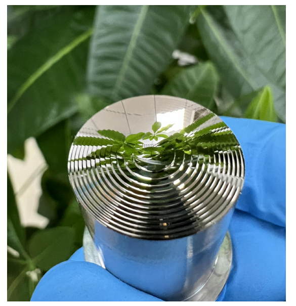
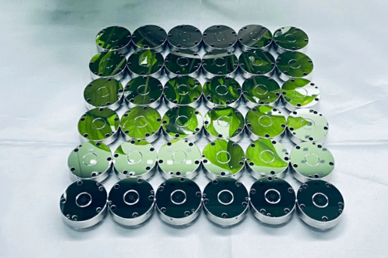
Temperature control matters in ultra precision machining because heat — not the cutting tool — is usually the largest single error source once tolerances fall below a few microns. A 1 °C change across a 100 mm steel component moves its length by roughly 1.1 µm, which is more than twice the ±0.5 µm band that ultra precision work is expected to hold. Controlling the temperature of the room, the machine, the coolant, the workpiece and the measuring instrument is therefore not a comfort issue. It decides whether a part is genuinely in tolerance, or only appeared to be in tolerance in the shop where it was made.
This article explains where thermal error comes from, how large it typically is, how it shows up on real optical components and mold inserts, and what an engineering buyer should verify before releasing a sub-micron job to any ultra precision machining service. If you are sourcing tight-tolerance parts for the first time, the supplier questions near the end are the ones worth asking before price.
How Much Does 1 °C Actually Move a Part?
Thermal expansion is linear and predictable, which makes it easy to quantify. Multiply the coefficient of thermal expansion (CTE) by the length and by the temperature change, and you have the error before a single cut has been made. The table below uses nominal published CTE values for material families commonly seen in precision work; actual values vary with grade, temper and temperature range, so they should be treated as an order-of-magnitude guide rather than a specification.
| Material family | Typical CTE (µm/m·°C) | Movement of a 100 mm feature per 1 °C | Practical implication |
|---|---|---|---|
| Invar / Kovar type low-expansion alloys | ~1–5 | ~0.1–0.5 µm | Chosen when dimensional stability outranks machinability |
| Tungsten | ~4.5 | ~0.45 µm | Stable, but hard and abrasive to machine |
| Titanium alloys | ~8.6 | ~0.86 µm | Low expansion, low thermal conductivity — heat stays in the cut zone |
| Hardened mold steel (HRC 48–52) | ~11–12 | ~1.1–1.2 µm | Typical for optical mold cores and mirror inserts |
| Stainless steel | ~16 | ~1.6 µm | Common structural choice, moderately thermally sensitive |
| Copper | ~17 | ~1.7 µm | High conductivity spreads heat quickly through the part |
| Aluminium | ~23 | ~2.3 µm | Fast to machine, fast to move dimensionally |
| PEEK | ~47 | ~4.7 µm | Engineering plastic; expansion dominates the error budget |
| PMMA | ~70 | ~7.0 µm | Optical plastic; tight tolerances need a very stable process |
Against a ±0.5 µm dimensional tolerance, an aluminium feature only needs about 0.2 °C of drift to consume the entire tolerance band, and a hardened steel feature needs less than 0.5 °C. That is why ultra precision machining is discussed in terms of thermal error budgets rather than machine accuracy alone. YISHUN Optical works to dimensional tolerances as tight as ±0.5 µm, form accuracy controlled within 0.1 µm and surface roughness down to Ra 1 nm — targets that simply cannot survive an unstable environment, regardless of how good the spindle is.
Where the Heat Actually Comes From
1. Ambient air and room gradients
Most shops think about the set point and ignore the gradient. A room held at 22 °C on average can still have a 2–3 °C difference between floor level and machine height, or a swing every time an HVAC compressor cycles or a roller door opens. Gradients are more damaging than a stable offset: a uniformly warm part expands predictably, while a part that is warm on one side and cool on the other distorts in a way no offset can correct.
2. The machine itself
Spindle bearings, linear drives, ballscrews, servo motors and hydraulic systems all inject heat into the structure. This produces the familiar pattern where the first components of a shift measure differently from those made three hours later. The machine has not lost accuracy; it has changed shape while warming toward steady state. Machines used for ultra precision turning and milling therefore need a defined warm-up routine, and ideally should run continuously rather than being started and stopped.
3. The cutting process
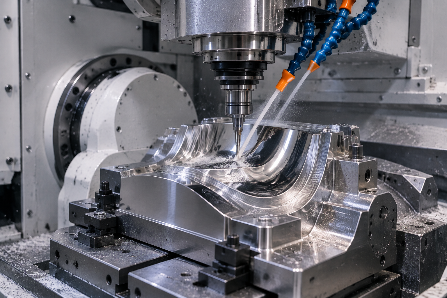
Almost all the mechanical energy of cutting becomes heat, and it enters the chip, the tool and the workpiece in proportions that change with material, tool geometry and depth of cut. In single point diamond turning and ultra precision milling the depth of cut is small, so total heat input is low — but the tolerance is also small, so a local temperature rise of a fraction of a degree in the tool–workpiece loop is no longer negligible. Coolant that is not itself temperature controlled becomes a heat source rather than a heat sink.
4. Handling, cleaning and human contact
Holding a small mold insert in a bare hand for thirty seconds can raise its temperature by several degrees. Solvent cleaning does the opposite through evaporative cooling. Carrying a part from a machine to a metrology room at a different temperature guarantees that the part will keep moving while it is being measured. These are the errors that are hardest to trace, because nothing about the machine or the program has changed.
What Thermal Drift Looks Like on the Finished Part
Thermal problems rarely announce themselves as “temperature”. They arrive as inconsistent parts, arguments about measurement, or a surface that will not reach the required finish. The table below maps the symptom to the likely cause.
| Symptom on the part or report | Likely thermal cause | What to check first |
|---|---|---|
| Size drifts steadily across a batch; early parts pass, later parts fail | Machine structure warming toward steady state | Plot dimension against machine running hours; review warm-up procedure |
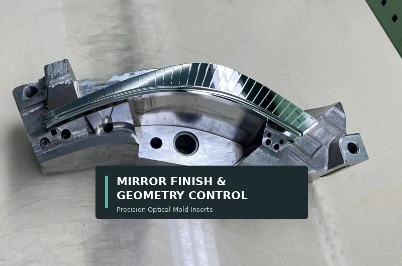
| Form or profile error on a lens, mirror or aspheric surface | Gradient between spindle, fixture and workpiece during a long cut | Form accuracy trend within one part; cutting strategy and cycle time |
| Mismatch or step where two setups meet | Part clamped or re-datumed at a different temperature | Soak time between operations; datum strategy |
| Supplier report and incoming inspection disagree by under a micron | Measurements taken at different temperatures | Whether the measurement temperature is stated on both reports |
| Surface roughness varies between otherwise identical parts | Instability in the tool–workpiece loop, or uncontrolled coolant temperature | Coolant temperature control; tool life and wear pattern |
How a Temperature-Stable Machining Environment Is Built
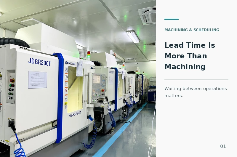
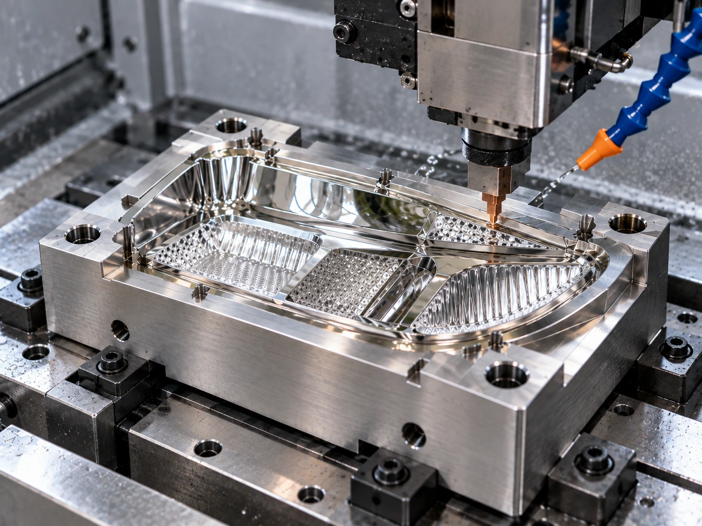
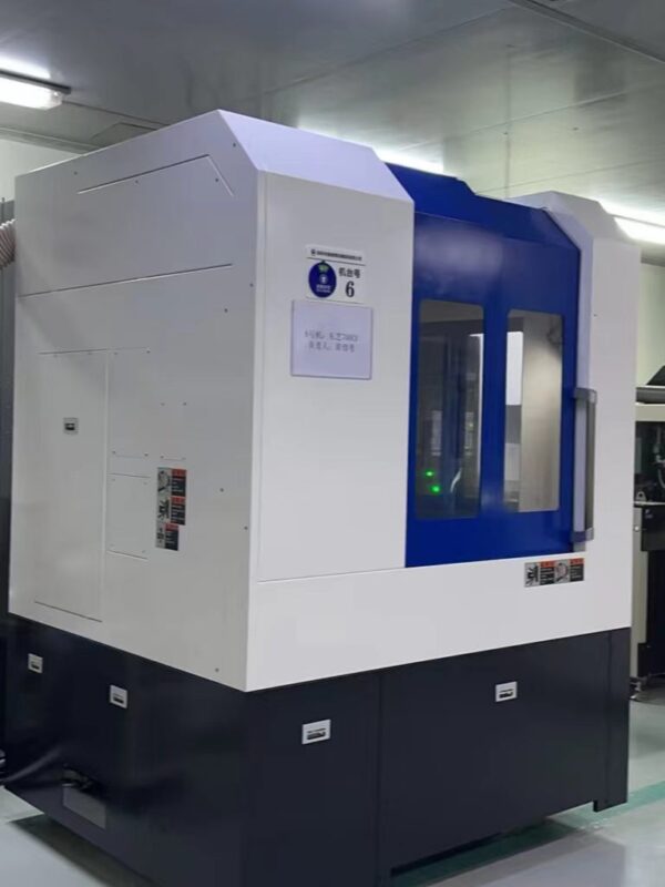
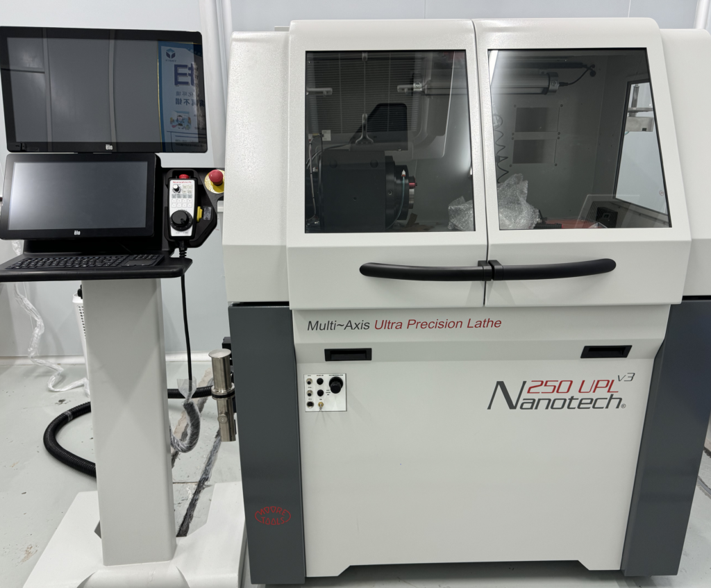
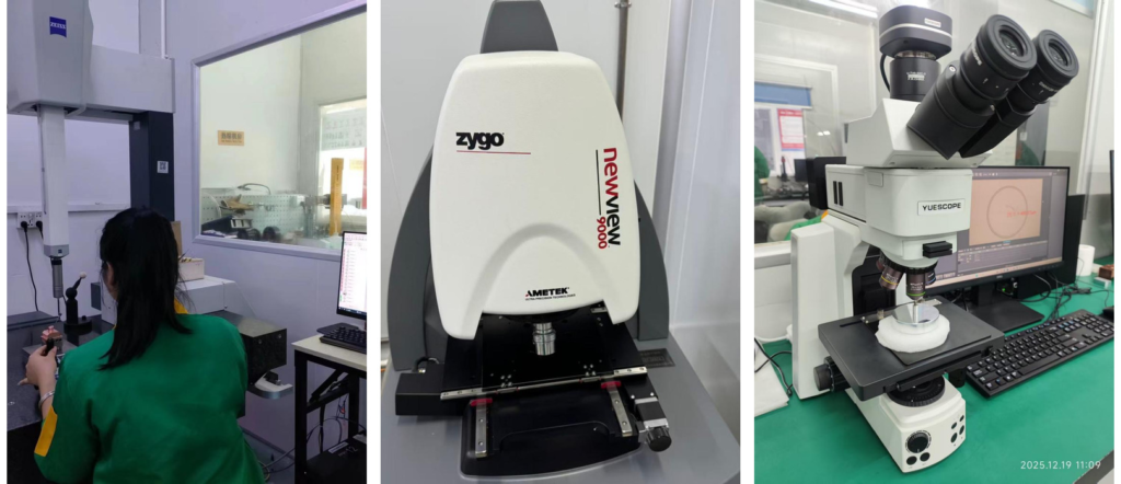
A credible ultra precision operation controls temperature at several levels at once rather than relying on air conditioning alone. YISHUN Optical machines in environmentally controlled clean room facilities, using Moore-type diamond lathes, Röders high-speed machining centres and ABB six-axis robots, with Zeiss and Zygo metrology available in the same controlled space. Several elements work together:
- A stable environment, not just a cold one. Consistency and low gradients matter more than the absolute set point.
- Thermal soak before the first cut. Material, fixture and machine are allowed to reach a common temperature so the first part is not the odd one out.
- Continuous rather than intermittent running. Pallet systems with automatic loading and unloading allow machining to run 24/6, which keeps the structure at a steady thermal state instead of cycling up and down every day.
- Single setup processing. Completing multiple operations in one setup removes the re-clamping and re-datuming steps where thermal state most often changes between features.
- Controlled coolant and controlled handling. Fluid temperature is treated as a process parameter, and finished surfaces are handled with the same discipline as measurement.
Metrology Needs the Same Temperature Discipline
20 °C is the internationally accepted reference temperature for dimensional measurement, and every drawing tolerance implicitly refers to it. If a part is machined in one thermal state and measured in another, the number in the inspection report describes the part at the moment of measurement, not the part your assembly will receive.
A sub-micron measurement is only meaningful if the temperature at which it was taken is known and recorded. In practice this means surface roughness testers, flatness interferometers, roundness testers, coordinate measuring machines and atomic force microscope inspection all need to sit in a controlled space, parts need to soak before verification, and the measurement conditions belong in the documentation alongside the results. Traceable inspection records that omit temperature leave a gap that only shows up later, when two parties measure the same part and disagree.
Material Selection Changes Your Thermal Risk
Two parts with identical drawings can behave completely differently depending on material. Low-expansion alloys such as Invar and Kovar are specified precisely because they hold dimension when temperature moves, and they are frequently chosen for metrology fixtures, reference components and optical mounts. Tungsten, ceramics, cemented carbides and optical crystals are also dimensionally stable, but they bring hardness, brittleness and thermal-cracking risks that shift the difficulty into the process rather than removing it.
At the other end, aluminium, copper, PEEK and PMMA move enough that thermal management dominates the error budget. Hardened mold steel in the HRC 48–52 range sits in between: manageable expansion, but limited thermal conductivity, so grinding and finishing heat concentrates locally instead of dissipating. A useful discipline is to tell your supplier the temperature at which the part must actually function, not only the temperature at which it should be inspected. A component that is machined and verified at 20 °C but works at 60 °C has a design problem no machining process can solve.
What Thermal Control Costs, and What It Saves
Temperature control has a real price: conditioned space, soak time before machining and before measurement, scheduling that favours single-setup jobs, and slower cutting strategies when heat input has to stay low. Those factors show up as lead time and unit cost, particularly on low-volume work where setup dominates.
The return is fewer rejects, less rework and less argument at incoming inspection — machining correctly the first time reduces scrap rates, lowers rework cost and extends tool life. The most common way buyers overspend is not by paying for thermal control, but by applying the tightest tolerance on the drawing to every dimension. Identify the two or three functional features that genuinely need sub-micron control, open up the rest, and the thermal effort concentrates where it changes product performance.
Questions to Ask Before You Award a Sub-Micron Job
These questions separate suppliers who manage temperature from suppliers who merely have air conditioning. Reputable engineering teams answer them without hesitation, and the answers are more informative than a quoted accuracy figure. You can raise them directly with the engineering team at YISHUN Optical when discussing a project:
- Is machining performed in a temperature-controlled environment, and how is stability monitored rather than just set?
- What warm-up or soak procedure runs before the first cut on a precision job?
- Is coolant temperature controlled, and is it treated as a recorded process parameter?
- At what temperature are final measurements taken, and does the inspection report state it?
- Which critical features are machined in a single setup, and which require re-datuming?
- What metrology verifies form accuracy and surface roughness — interferometer, profilometer, CMM, or a combination?
- How is drift detected and corrected across a longer production run rather than on a first article only?
What to Include in Your RFQ
Quotation accuracy on precision work depends almost entirely on the completeness of the technical requirements you supply. Before requesting a quotation for ultra precision turning, milling and grinding, prepare the following:
- A drawing with clearly identified datums, and the measurement temperature stated explicitly
- A distinction between functional tolerances and general tolerances
- Material specification including grade, temper or hardness
- Surface roughness requirement (Ra or RMS) and any form accuracy requirement
- The operating temperature and environment of the finished component
- Quantity, delivery schedule, and whether repeat batches must match each other dimensionally
- The inspection documentation you need, and whether measurement conditions must be recorded
Three Misconceptions Worth Correcting
“An air-conditioned workshop is temperature controlled.” Air conditioning manages an average. Ultra precision work is affected by stability over hours and by gradients across metres, both of which a standard HVAC set point ignores.
“Only the machine needs to be thermally stable.” The workpiece, fixture, tool, coolant, gauge and metrology room all belong to the same error chain. Stabilising one element while ignoring the others simply relocates the error.
“Thermal error is random, so it cannot be managed.” Most thermal error is systematic and repeatable. Because it follows physics, it can be measured, budgeted, reduced by soak and warm-up procedures, and partly compensated — provided someone is actually tracking it.
Frequently Asked Questions
What temperature should an ultra precision machining shop be held at?
20 °C is the conventional reference temperature for dimensional metrology, so it is the natural target. What matters more than the number is stability over time and uniformity across the space: a shop held steady at 21 °C will outperform one that averages 20 °C while swinging 3 °C every hour.
How long should a part soak before it is measured?
It depends on mass, material, thermal conductivity and how far the part is from the reference temperature. Small metal inserts equalise relatively quickly, while heavier assemblies and low-conductivity materials need considerably longer. Rather than assuming a figure, ask the supplier what soak procedure it applies and whether soak time is documented.
Does temperature control affect surface roughness, or only dimensions?
Both. Dimensional and form effects are direct, driven by expansion. Roughness is affected indirectly: an unstable tool–workpiece loop and fluctuating coolant temperature change cutting conditions from pass to pass, which shows up as inconsistent finish and uneven tool wear.
Can thermal error be compensated in the control system instead?
Partly. Machine thermal compensation and measured offsets handle predictable growth in the machine structure. They cannot correct a gradient across the workpiece, a part that is still cooling while being cut, or a mismatch between machining temperature and measurement temperature.
Why do my incoming inspection results differ from the supplier’s report?
Below about a micron, the three usual causes are different measurement temperature, different instruments or probing strategy, and different datum interpretation. Temperature is the easiest to eliminate: require the measurement temperature to be stated on both reports and compare like with like.
Which materials are most sensitive to temperature during machining?
Optical plastics such as PMMA, engineering plastics such as PEEK, then aluminium and copper, are the most sensitive. Titanium is dimensionally moderate but retains heat in the cut zone because of low conductivity. Invar, Kovar and tungsten are the least sensitive dimensionally, which is why they appear in metrology and reference applications.
Conclusion
Below a few microns, precision is a thermal engineering problem as much as a cutting problem. The tolerance you write on a drawing is only real if the room, the machine, the coolant, the part and the gauge were at a known and stable temperature — and if that temperature is recorded in the inspection report. When you evaluate a supplier, ask how thermal state is controlled and verified rather than only what accuracy figure the machine is capable of.
If you have a component with sub-micron dimensional, form or surface requirements, send the drawing together with the material, operating temperature and inspection expectations, and talk to our ultra precision machining team about the process route, metrology plan and documentation your project needs.