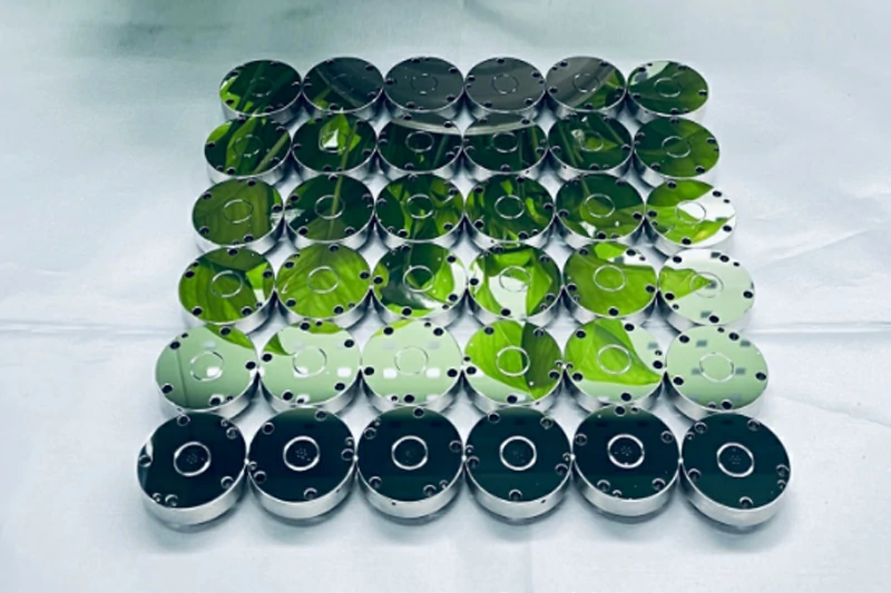
How to Avoid Burrs in Ultra Precision Machined Components
Burrs are an unavoidable by-product of any cutting, milling, drilling or turning operation, but their size, shape and location can be controlled. In ultra precision machining, the practical way to avoid problematic burrs is a combination of sharp tooling, correct tool geometry, optimised cutting parameters, a rigid machine setup and a defined deburring or edge-break step, so that every edge meets the part’s function, fit and surface requirements.
Edge quality is rarely the first thing engineers discuss when they ask for a precision part, yet it decides whether components seal, slide, assemble and perform optically. This guide walks through why micro burrs form, how to prevent them at the machining stage, and what to specify when you ask a supplier for burr-free or edge-controlled parts.
Why Burrs Matter in Ultra Precision Machining
For most buyers, a burr is not a cosmetic issue. It is a functional one, and an uncontrolled edge can quietly drive up scrap, rework and field failure. A raised lip of displaced material at an edge can:
- Prevent two mating faces from seating fully, which breaks a seal or changes a precision gap.
- Interfere with sliding or rotating fits, causing drag, noise or accelerated wear.
- Scatter or block light in optical seats, apertures and mirror mounts.
- Break off later in service and contaminate a clean or fluid path.
- Trigger assembly failure or rejection during incoming inspection.
When tolerances are specified at ±0.5 µm and surface roughness at Ra 1 nm, an uncontrolled burr of even a few microns is larger than the allowed error band. That is why edge control has to be designed into the process, not added as an afterthought. If you are evaluating ultra precision machining services, ask early how edge quality is held, not only how flat or smooth the face is.
What Causes Burrs in Precision Machining
A burr forms when the cutting tool separates material but a thin layer is plastically deformed and pushed out instead of being cleanly sheared. Several factors decide how large that burr becomes, and they interact with each other on every feature.
Tool Wear and Tool Sharpness
A worn or rounded edge smears material rather than cutting it. In micro machining, the tool edge radius is a meaningful fraction of the chip thickness, so a dull tool produces larger rollover burrs. Keeping tools sharp and replacing them on a monitored schedule is the single most effective burr-control step, and it also protects surface finish.
Cutting Direction and Exit Conditions
Burrs are largest where the tool exits the material, because there is no support behind the last cut. The direction of travel, climb versus conventional cutting, and how the tool leaves the edge all change burr size. Planning tool paths so critical edges are cut last, while support is still present, reduces the worst exits.
Material Behaviour
Ductile metals such as copper, aluminium, titanium and many superalloys form larger, more adherent burrs than brittle materials. Hardness, work hardening and grain structure all matter. The same tooling that cuts cleanly in one alloy can leave heavy burrs in another, so the process must be matched to the material.
Machine Rigidity and Vibration
Chatter and deflection let the tool rub instead of cut, which enlarges burrs and worsens surface finish. A stable, thermally controlled setup with minimal overhang keeps the cut predictable and repeatable across a production run.
Common Types of Burrs and How to Control Them
Not every burr is the same. Naming the type helps you choose the control and tells the supplier what to watch for.
| Burr type | Where it appears | Primary control |
|---|---|---|
| Poisson burr | Side of a slot or wall as material bulges sideways under load | Sharp tool, lower feed, rigid support |
| Rollover burr | Exit edge of a drilled or milled feature | Climb cutting, optimised exit path, sharp drill |
| Tear or breakout burr | Brittle or layered materials at the exit | Backing support, reduced engagement, proper process |
| Heat-affected burr | Where rubbing replaces cutting | Correct speeds and feeds, coolant, sharp tooling |
How to Prevent Burrs at the Machining Stage
The cheapest burr is the one you never make. Most burr prevention happens before deburring is considered, by controlling the cut itself.
Tool Geometry and Sharpness
Use the smallest practical edge radius and the correct rake angle for the material. In micro features, regrind or replace tools on a schedule based on part count and measured edge quality rather than on a fixed guess.
Cutting Parameters
Feed and depth of cut influence whether the chip forms cleanly. Extremely low feeds can increase rubbing; too high a feed can tear the edge. The right window is material and tool specific, and it should be proven on a first-article part before volume production.
Climb Versus Conventional Cutting
Climb cutting generally leaves a smaller exit burr on the finished side because the tool engages the supported stock first. The choice depends on the feature and the machine, but it is a powerful lever for edge quality that is often overlooked.
Rigid, Thermally Stable Setup
Minimise tool overhang, hold the part firmly, and control temperature so the geometry does not drift during the cut. At a ±0.5 µm tolerance, a few tenths of a degree of thermal growth can matter more than the cutting itself.
Choosing the Right Process Route
Burr size is tied to process choice. Turning, milling, grinding, lapping and polishing each leave a different edge signature, and the route should be chosen for the edge as well as the face.
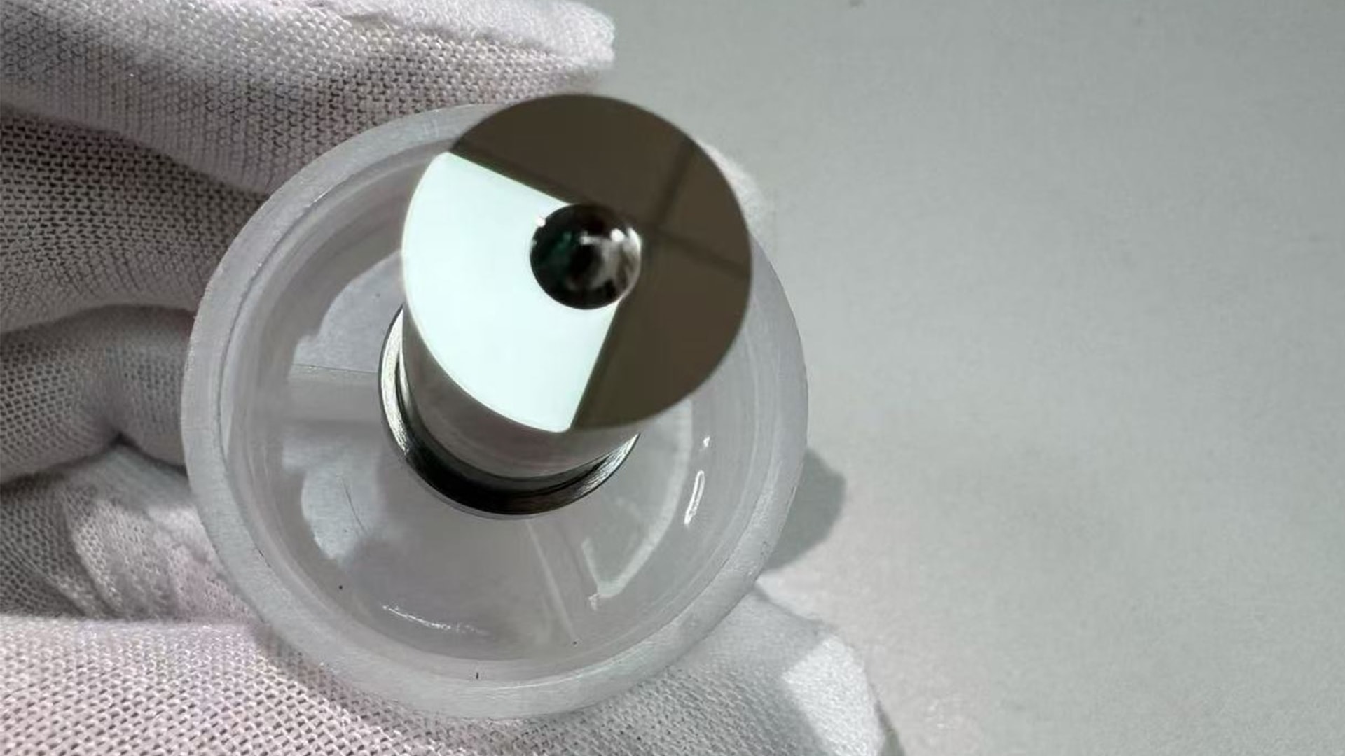
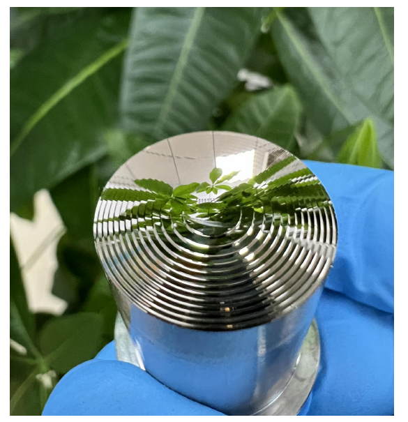
- Single-point diamond turning (SPDT) can produce optical-grade faces with very small edge disturbance on suitable materials.
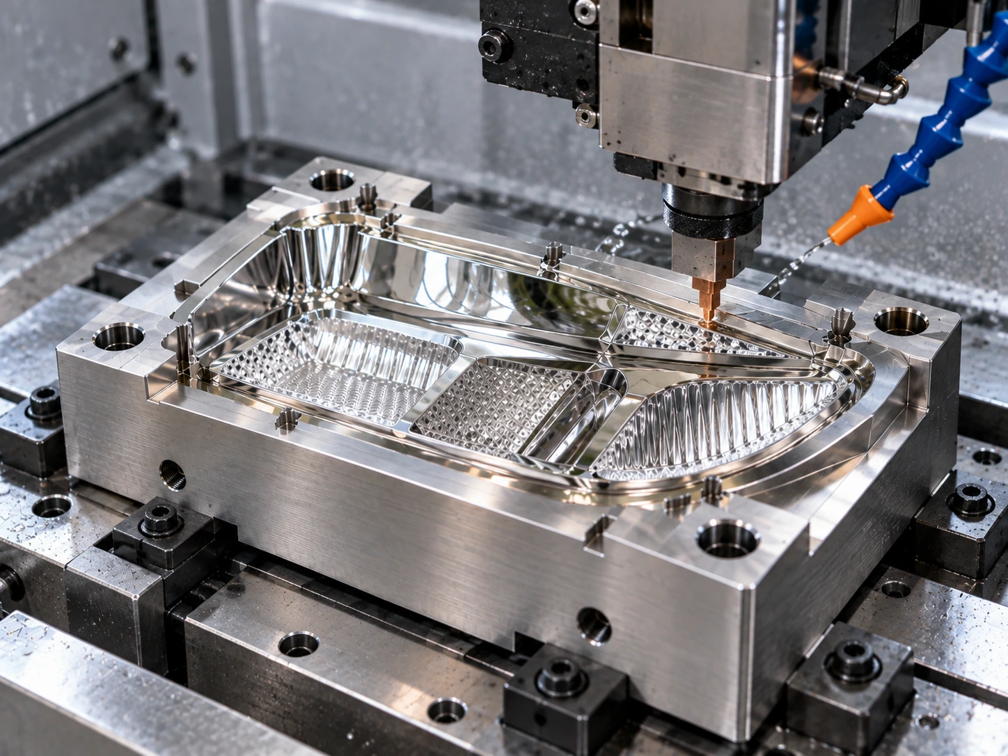
- Ultra precision milling handles complex 3D shapes but needs careful exit management on micro features.
- Grinding and lapping give controlled edges on hard materials and can be followed by polishing for an optical finish.
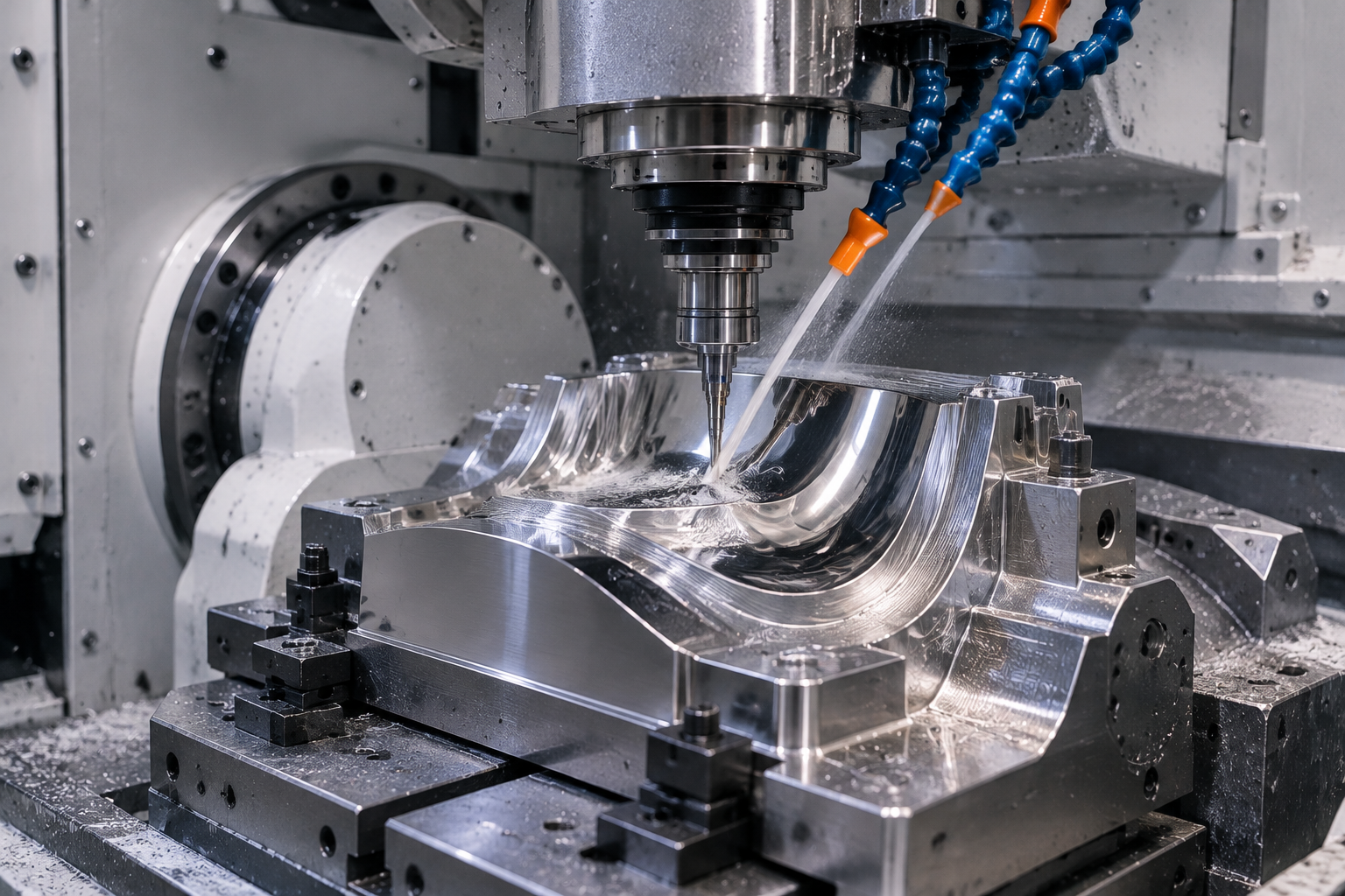
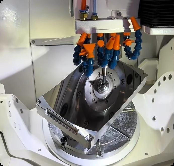
Finishing a part in a single-setup five-axis machining route reduces the number of handling and re-clamp steps where edges are re-cut and new burrs are created. Fewer setups usually means fewer uncontrolled edges, and it also protects the tight datums that precision parts depend on.
Deburring and Edge Control for Precision Components
Even with good cutting, a defined edge treatment is often required, and the method should match the part rather than be applied blindly. A burr removed by the wrong method can cost more than the burr itself if it damages a critical edge.
- Mechanical edge break with controlled media or brushes for non-critical edges.
- Abrasive flow or drag finishing for consistent edges on complex or fragile geometry.
- Electropolishing or chemical passivation where a clean, rounded edge and a corrosion-resistant surface are needed.
- Cryogenic or thermal deburring for hard-to-reach internal features, used with care on tight tolerances.
The key is to specify the edge, not just to ask for burrs to be removed. An undefined request leads to inconsistent results. Define an edge-break radius, which edges matter, and an acceptable maximum burr height so the supplier can prove the result.
How Surface Finish and Burrs Are Linked
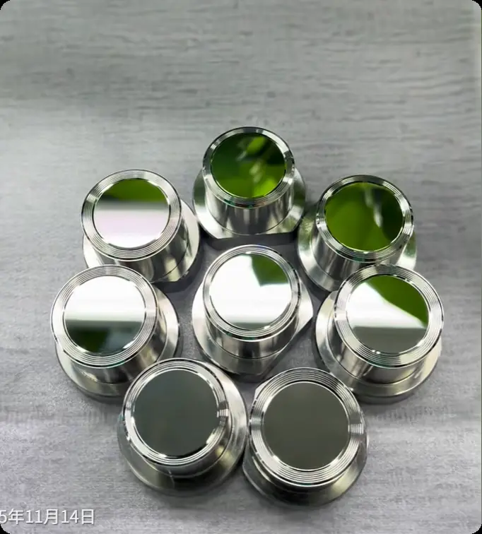
Surface roughness and edge quality are two views of the same cut. A process that leaves a clean Ra 1 nm face usually also leaves a smaller, more predictable burr, because the tool is cutting rather than smearing. Conversely, a rough, rubbed edge tends to carry a larger burr. That is why specifying Ra, measurement method and edge condition together gives a supplier a complete picture. Our ultra precision machining service treats surface finish and edge control as one specification, verified with Zeiss and Zygo metrology rather than judged by eye.
Measuring and Inspecting Edge Quality
You cannot hold an edge you cannot measure. For precision parts, edge quality is checked with a mix of optical microscopy, tactile or laser profiling, and sometimes cross-section evaluation on a first article. The acceptance limit should be written as a number, such as a maximum burr height or a minimum edge-break radius, referenced to a datum on the drawing. Visual inspection alone is not enough at micron scale, because the burr that blocks an optical seat may be smaller than what the eye can confirm reliably.
Specifying Burr Requirements to Your Supplier
To get consistent parts, tell the supplier what the edge must do, not only that it should be burr free. A useful specification includes the items below.
| What to define | Why it matters |
|---|---|
| Material and hardness | Decides tooling and burr tendency |
| Critical edges versus non-critical edges | Focuses effort where function lives |
| Allowed edge-break radius | Turns edge quality into a measurable number |
| Maximum acceptable burr height | Gives inspection a pass or fail limit |
| Surface roughness Ra and method | Links finish to edge behaviour |
| Tolerance and datum references | Ensures edges are measured on the right body |
Send a drawing that marks the edges that matter. A supplier who receives a clear edge specification can prove it with first-article measurement instead of a verbal promise, which is what tight-tolerance work requires.
Burr Control in Prototyping Versus Production
Edge control is easiest when it is proven once and then locked. On a prototype, the supplier should test tooling, parameters and exit paths to find the combination that keeps burrs within the limit, then document it as the production process. Carrying that proof into volume runs prevents the common failure where the first article is clean but production drifts. For buyers, the practical question to a supplier is simple: how is the edge verified on every lot, not only on the sample.
How YISHUN Controls Edge Quality
YISHUN Optical has built edge and surface control into its ultra precision process over 20 years of experience. Capabilities that support burr-free results include tolerances as tight as ±0.5 µm, surface roughness down to Ra 1 nm, single-point diamond turning on Mohr diamond lathes, five-axis machining on RODERS centres, and verification with Zeiss and Zygo metrology. ISO 9001 and ISO 14001 systems back the inspection record for each component. None of this removes the need to define the edge, but it gives a measurable, repeatable path from drawing to finished part.
Frequently Asked Questions
Can burrs be completely eliminated in machining?
No cutting process removes material without some edge disturbance. The practical goal is to make burrs small, predictable and located where they do not affect function, then to control or remove them with a defined edge treatment. Claiming zero burr on every edge is not realistic for machined metal parts.
Which process gives the smallest burrs?
Single-point diamond turning and fine grinding tend to leave the smallest, most controlled edges on suitable materials. The best choice depends on geometry, material and the required surface. A ultra precision machined part often combines processes, finishing with polishing or lapping for the critical faces.
Does a better surface finish mean fewer burrs?
Usually, yes. A clean cut that produces a low Ra face normally also leaves a smaller burr, because the tool is shearing rather than smearing. The two should be specified together so the supplier controls both at once.
How do I tell a supplier what edge I need?
Mark the critical edges on the drawing, give an allowed edge-break radius and a maximum burr height, and state the Ra and measurement method. A clear specification lets the supplier prove the result with first-article data rather than an opinion.
Is deburring enough to fix a bad edge?
Deburring helps, but it cannot recover a dimension or a profile that was lost to poor cutting. Preventing the burr at the machining stage is cheaper and more reliable than removing a large one later. In tight-tolerance work, aggressive deburring can even damage the edge you are trying to protect.
What materials are hardest to deburr?
Ductile and very hard or brittle materials such as copper, titanium, carbides and optical crystals need process-specific control. The right tooling, cutting window and finishing route matter more than the deburring step alone, so material should be stated up front.
Conclusion
Avoiding burrs in ultra precision machined components is not one action but a chain: sharp tooling, the right parameters, a stable setup, a sensible process route and a defined edge specification. Buyers who state the edge requirement up front get parts that seal, fit and perform as designed. If you need help turning an edge and surface specification into a repeatable process, discuss your precision machining requirements with the YISHUN team and share the drawing that marks the edges that matter.