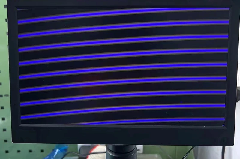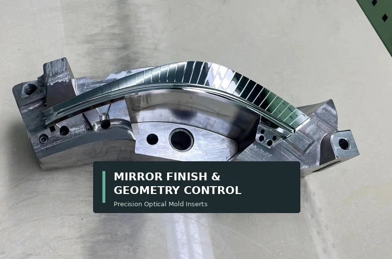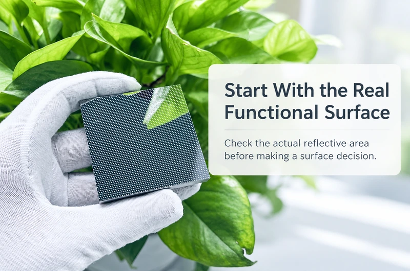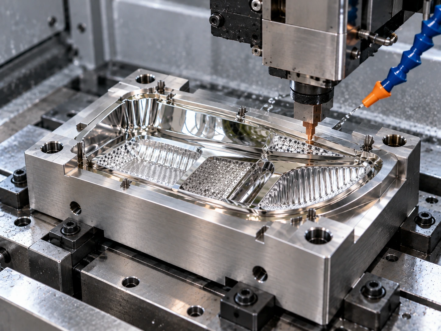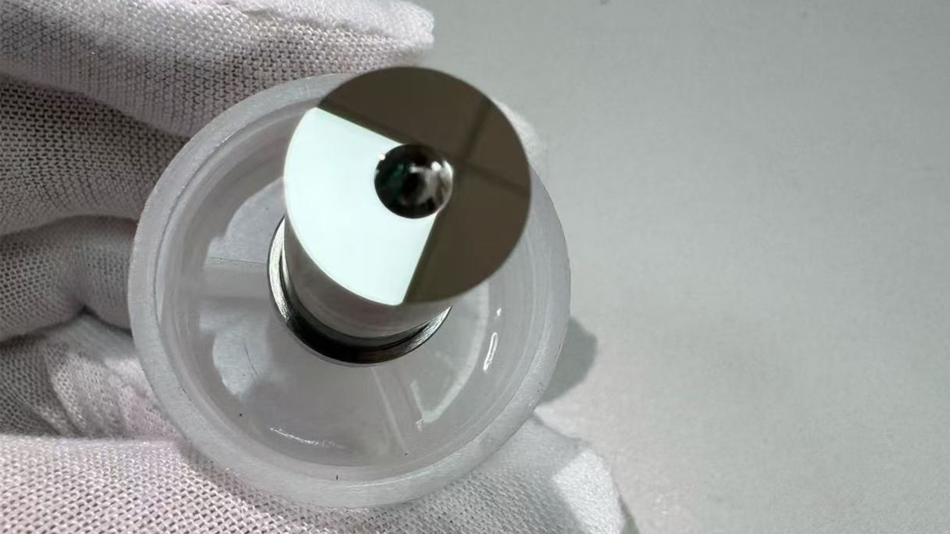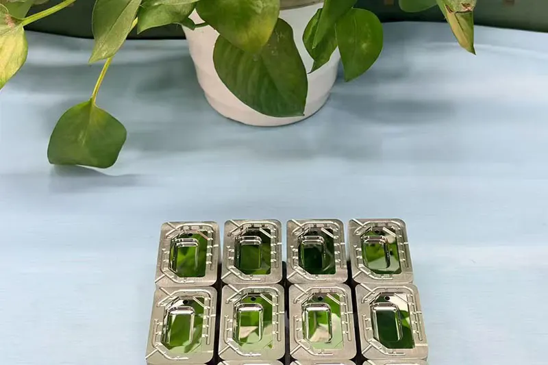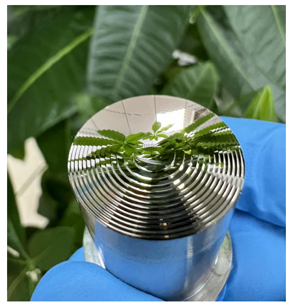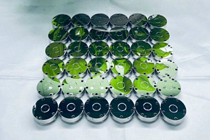
An optical mold core can display a flawless, mirror-like reflection to the naked eye while still producing plastic lenses plagued by wide-angle haze, contrast loss, and diffraction flares. Visual brightness only indicates that surface variations are smaller than the resolving limit of human vision under ambient light; it does not guarantee optical-grade surface fidelity.
When collimated or high-intensity light traverses an injection-molded lens, it interacts with micro-topographical errors replicated directly from the mold cavity. Eliminating these defects requires understanding the distinct physical wavelengths across the tooling surface—separating standard cosmetic gloss from deterministic optical finishing. This guide breaks down the surface mechanisms that cause flare and haze, evaluates where standard mold polishing fails, and provides an engineering framework to specify and verify mold inserts for imaging-grade optics.

The “Cosmetic Mirror” Illusion: Why Visual Brightness Fails in Precision Optics
Visual brightness measures specular reflection, which occurs when a surface reflects incoming light rays at the same angle. A technician examining a finished mold core under standard inspection lamps can easily verify that the metal is free of macro-scratches, pits, and orange peel.
However, optical transmission depends on wavefront coherence. Light passing through an optical element does not merely bounce off a boundary; it refracts through a structured boundary profile. If the mold insert features microscopic height deviations across specific spatial intervals, the injected polymer replicates those variations down to the sub-micron scale.
When photons encounter these replicated micro-structures:
- Specular transmission degrades: A portion of the wavefront shifts out of phase.
- Diffraction occurs: Periodic structures redirect light into discrete side orders, generating visible ghost images or flares.
- Random scatter increases: Non-periodic sub-micron roughness scatters photons randomly, creating background veiling glare and perceived fogging (haze).
A mold surface can easily pass an SPI A1 or A2 visual mold inspection while harboring critical microscopic errors that compromise an optical system’s Modulation Transfer Function (MTF).
What the Eye Misses: Micro-Topography Defects that Trigger Scatter, Haze, and Flare
Surface errors on an optical mold core exist along a continuum of spatial frequencies. Addressing stray light requires isolating which spatial frequency band is responsible for each specific optical artifact.
| Frequency Regime | Primary Defect Classification | Physical Surface Features | Primary Optical Impact |
| Low-Spatial Frequency | Form Error / Figure Deviation | Sag deviation, irregularity, power error | Wavefront aberration, defocus, image distortion |
| Mid-Spatial Frequency (MSF) | Waviness / Periodic Tool Marks | Diamond turning cusps, raster steps, tool chatter | Structured flare, diffraction rings, ghost halos |
| High-Spatial Frequency | Micro-Roughness ($Ra, Rq / Sq$) | Sub-micron fissures, grit marks, micro-pits | Wide-angle diffuse scatter, veiling glare, background haze |
High-Spatial Frequency Roughness ($Ra$, $Rq/Sq$): The Source of Wide-Angle Haze
High-spatial frequency errors encompass surface irregularities with spatial wavelengths shorter than roughly $10\,\mu\text{m}$ to $20\,\mu\text{m}$. Often quantified as centerline average roughness ($Ra$) or root-mean-square roughness ($Rq$ or areal $Sq$), these nano-scale variations act as isotropic scattering sites.
When light hits high-spatial roughness on a molded lens, it undergoes wide-angle diffuse scatter. The direct visual consequence is haze—a milky background appearance and reduced contrast across the field of view. Hand-polishing using loose abrasives often leaves random micro-grooves and sub-surface deformation that directly increase high-spatial scatter.
Mid-Spatial Frequency (MSF) Errors & Turning Ridges: The Engine Behind Diffraction Flares
Mid-spatial frequency errors occupy the critical band between low-order figure errors (shape and power) and high-spatial roughness—typically spanning spatial periods from $10\,\mu\text{m}$ to several millimeters.
On optical tooling manufactured via Single-Point Diamond Turning (SPDT) or sub-aperture computer-controlled polishing, MSF errors typically manifest as:
- Periodic cusps and feed marks: Regular spiral grooves left by diamond cutting edges or raster milling toolpaths.
- Step pitch rings: Concentric ridges caused by machine micro-vibrations or lead screw errors.
Because these periodic structures repeat systematically across the surface of the mold insert, they act as circular diffraction gratings. When a bright light source (such as a headlight or the sun) enters the molded lens, the periodic ridges diffract the light into structured halos, starbursts, and flare rings.
Edge Roll-Off and Form Distortions: Uncontrolled Stray Light Deflection
During traditional mold cavity polishing, compliant polishing bobs compress more heavily near edges, optical steps, and aperture boundaries. This uneven material removal causes edge roll-off (rounding of clear apertures) and localized form distortion. Light striking these rounded boundaries deviates unpredictably into the optical path, generating asymmetrical veiling flare.
Mold Core Defect to Optical Defect Matrix
| Mold Core Defect Type | Spatial Domain / Feature Size | Visual Appearance on Steel Core | Optical Manifestation on Molded Lens | Primary Manufacturing Cause |
| High-Spatial Roughness | $\lambda < 10\,\mu\text{m}$ ($Ra / Sq$) | Bright mirror finish; clear reflections | Wide-angle scatter, background haze, low image contrast | Inadequate fine abrasive lapping, sub-surface material tears |
| Periodic Turning Ridges (MSF) | $10\,\mu\text{m} \le \lambda \le 2\,\text{mm}$ | Clear, highly reflective surface | Structured flare rings, concentric halo, starburst patterns | Tool feed rate, tool nose radius wear, diamond turning dynamics |
| Random Micro-Scratches | Width $< 1\,\mu\text{m}$, Length $> 50\,\mu\text{m}$ | Rarely visible without darkfield lighting | Asymmetric line glare, localized flare streaks | Contaminated diamond paste, non-uniform manual strokes |
| Edge Roll-Off (Form Defect) | Outer 5–10% of clear aperture | Appears smooth and polished | Edge scatter, off-axis beam leakage | Over-polishing with soft, compliant pads or felt bobs |
SPI Mold Finishes vs. True Optical Polishing: Why Traditional Toolmaking Falls Short
Standard plastic injection molding relies on surface finish standards developed by the Society of the Plastics Industry (SPI). While SPI standards work well for consumer enclosures, automotive trim, and clear packaging, they fail to meet the rigorous demands of imaging systems.
| Polishing Paradigm | Tooling Mechanics | Surface Action | Optical Consequence |
| Traditional Toolroom Polish | Compliant felt bobs, manual sticks, hand rotary spindles | Applies variable local pressure; smears material into microscopic valleys | Rounds sharp edges; induces unmeasured mid-spatial waviness |
| Deterministic Optical Finishing | Rigid/semi-rigid laps, planetary kinematics, controlled slurries | Uniform material removal down to sub-atomic/nanometer thresholds | Clears sub-surface damage while preserving precise geometric figure ($PV$) |
The Limitations of SPI A1/A2 Standards
- SPI A1 / A2 definitions: Standard toolroom polishing relies on progressive grades of diamond compounds (such as 3-micron or 6-micron pastes) applied with rotary tools, felt bobs, and wooden sticks. The goal is the elimination of visible EDM marks and machining lines.
- The optical flaw: Manual buffing rubs down high peaks while smearing material into microscopic valleys. This creates an amorphous layer that looks shiny but possesses undulating waviness (MSF errors) and localized slope deviations.
The Physics of Deterministic Optical Finishing
True optical tooling requires deterministic finishing where material removal is precisely controlled across low-, mid-, and high-spatial frequency bands. Implementing dedicated precision optical polishing and lapping services removes sub-surface damage layers and suppresses periodic tooling marks without distorting the underlying geometric prescription.
| Evaluation Metric | Standard Toolmaker Polish (SPI A1) | Optical Polishing & Lapping |
| Primary Objective | Cosmetic gloss; easy part ejection | Wavefront preservation; low scatter transmission |
| Roughness Control | Primarily visual, rarely specified past $Ra \approx 0.02\,\mu\text{m}$ | Multi-parameter specifications ($Sa, Sq < 1\text{–}5\,\text{nm}$ depending on application) |
| Mid-Spatial Frequency Management | Uncontrolled; often introduces manual waviness | Controlled via rigid/pitch laps or specialized smoothing runs |
| Edge Integrity | Prone to edge roll-off and radius deformation | Strict clear-aperture slope retention up to component borders |
| Primary Process Medium | Rotary hand-tools, loose paste on felt/wood | Pitch polishing, chemical-mechanical planarization, fluid jet |
Beyond Visual Inspection: Metrology That Truly Predicts Lens Performance
Relying on ambient visual checks or standard mechanical stylus profilometers will not identify the root causes of stray light. Stylus tips typically have radii between $2\,\mu\text{m}$ and $5\,\mu\text{m}$, causing them to physically bridge over narrow sub-micron fissures and high-frequency tool cusps.
Predicting optical performance requires non-contact, areal optical metrology.
Recommended Metrology Methods
- White Light Interferometry (WLI) / Coherence Scanning Interferometry (CSI): Captures areal surface topography over small fields of view ($100\,\mu\text{m} \times 100\,\mu\text{m}$ to $1\,\text{mm} \times 1\,\text{mm}$), measuring $Sa$ and $Sq$ down to sub-nanometer levels.
- Phase-Shifting Laser Interferometry: Measures overall form error ($PV$, Power, Irregularity) and lower-frequency waviness across the entire optical aperture.
- Atomic Force Microscopy (AFM): Reserved for high-criticality applications requiring sub-angstrom roughness characterization over microscopic fields.
The Importance of Power Spectral Density (PSD)
Specifying an average roughness parameter ($Ra$) only provides an integrated amplitude measurement; it does not indicate whether roughness is distributed randomly or concentrated into periodic diffraction intervals.
Power Spectral Density (PSD) plots the amplitude of surface errors as a function of their spatial frequency:
$$\text{Spatial Frequency } (f) = \frac{1}{\text{Spatial Wavelength } (\lambda_s)}$$
By examining the PSD curve of an optical mold core:
- Spikes in the mid-frequency band highlight recurring diamond tool cusps or machine resonance that directly cause diffraction flare.
- Elevated high-frequency plateaus signify general micro-roughness that drives wide-angle haze.
Including PSD limits on manufacturing drawings prevents toolmakers from polishing an insert into a cosmetically shiny state that remains optically defective.
Engineering Solutions: How to Specify and Troubleshoot Optical Mold Inserts
Resolving flare and haze issues requires separating tooling-induced errors from injection process anomalies, followed by defining strict manufacturing specifications.
| Diagnostic Step | Inspection Target | Verification Method | Corrective Engineering Action |
| 1. Stress vs. Surface Triage | Molded optic | Cross-polarized light inspection | If birefringence bands align with gates, modify pack/hold cycle. If uniform, inspect tooling topography. |
| 2. Artifact Orientation | Flare / streak pattern | Rotate mold insert inside cavity | If flare pattern rotates with insert, tooling cusps or directional micro-grooves are confirmed. |
| 3. Replication Fidelity | Mold insert vs. lens replica | Areal 3D optical profilometry (WLI) | If replica matches tooling $Sq$ and MSF cusps, rework mold surface via deterministic lapping. |
Procurement and Drawing Specification Checklist
To avoid receiving mold cores that are cosmetically bright but optically flawed, incorporate explicit micro-topography parameters into tooling procurement packages:
- Specify Areal Parameters ($Sa / Sq$) Instead of Linear $Ra$: Linear stylus scans miss directional grooves. Specify 3D areal surface roughness over a defined measurement area (e.g., $Sq \le 2\,\text{nm}$ over a $250\,\mu\text{m} \times 250\,\mu\text{m}$ window).
- Define Mid-Spatial Frequency Tolerances: Set explicit slope error limits (e.g., root-mean-square slope $R\Delta q$ or areal slope $S\Delta q$) or mandate upper bounds on PSD curves across designated frequency ranges.
- Require Pre- and Post-Coat Metrology: If the mold core receives hard coatings (such as nickel-phosphorus, DLC, or chrome nitride), confirm that plating deposition does not increase high-frequency roughness.
- Mandate Specialized Post-Turning Smoothing: Specify non-directional, deterministic optical mold core polishing to knock down single-point diamond turning peaks without introducing edge roll-off.
Eliminating Optical Flare at the Source
Visual brightness is an aesthetic attribute, not an optical metric. When molded optics exhibit unexplained haze, starbursts, or contrast loss, the underlying cause is frequently traced back to sub-micron tooling topography: mid-spatial frequency ridges acting as diffraction gratings, or high-spatial roughness diffusing transmitted wavefronts.
Eliminating these optical defects requires moving beyond conventional SPI toolroom polishing standards. By establishing strict areal roughness limits ($Sq$), monitoring Power Spectral Density curves, and utilizing dedicated optical lapping and polishing techniques, engineering teams can ensure their mold inserts deliver predictable, scatter-free performance in mass production.
Key Takeaways
- Cosmetic Gloss vs. Optical Transmission: A mold core that looks mirror-bright can still induce severe flare and haze; visual gloss does not correlate with wavefront integrity.
- Root Causes of Haze: High-spatial frequency roughness ($Sq$) and sub-surface material tears create random, wide-angle scatter, degrading contrast and producing haze.
- Root Causes of Flare: Periodic mid-spatial frequency (MSF) errors—such as turning cusps and machine vibrations—act as circular diffraction gratings, creating starbursts and structured halos.
- Why SPI Standards Fail: SPI A1/A2 finishes rely on manual buffing that smears metal and rounds edges; precision optics require deterministic optical lapping and polishing.
- Actionable Metrology: Stylus profilometers bridge over critical micro-defects; engineers should specify White Light Interferometry (WLI) and Power Spectral Density (PSD) limits on drawings.
FAQ
Can an anti-reflective (AR) coating on the molded lens cover up haze caused by mold core roughness?
No. Anti-reflective thin-film coatings only minimize Fresnel reflection losses at refractive interfaces. They replicate the underlying substrate topography. If the molded lens surface contains micro-roughness or mid-spatial frequency ridges transferred from the mold core, the AR coating will follow those contours, leaving scattered light and diffraction flare unaffected.
How does diamond turning groove spacing correlate with the angle of diffraction flares?
The angle of diffracted light ($\theta$) follows the grating equation:
$$\sin(\theta) = \frac{m \cdot \lambda}{d}$$
where $m$ is the diffraction order, $\lambda$ is the wavelength of light, and $d$ is the groove spacing (tool feed per revolution). Smaller feed rates yield tighter groove spacing, which diffracts stray light at wider angles, whereas larger spacing produces closely spaced diffraction rings near the central beam.
Why can improper ultrasonic cleaning ruin an optically polished mold core?
Aggressive ultrasonic cleaning at incorrect frequencies or with improper chemical cavitation can cause micro-pitting on polished steel and nickel-phosphorus coatings. These microscopic pits fall directly into the high-spatial frequency band, converting a scatter-free mold surface into one that generates heavy wide-angle haze.
How do I tell if haze is caused by the mold core or by the molding process?
Inspect the molded part under cross-polarized light to check for internal stress birefringence, and verify that processing conditions are not causing material degradation or incomplete drying (which generates internal micro-voids). If the internal polymer structure is uniform and clear, test the lens on a non-contact surface profilometer: if surface roughness matches the cavity topography, the mold core is the primary contributor.