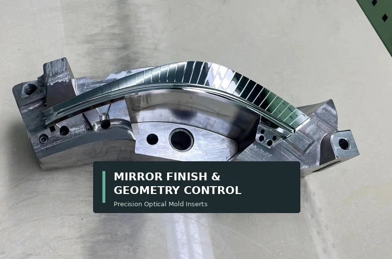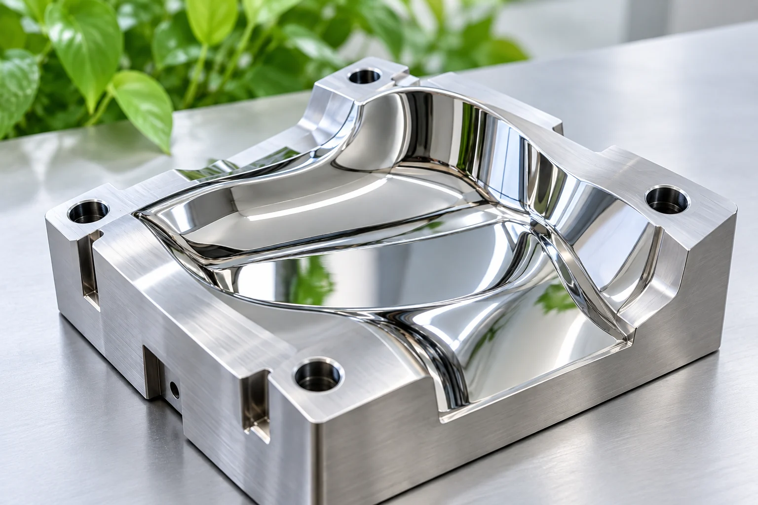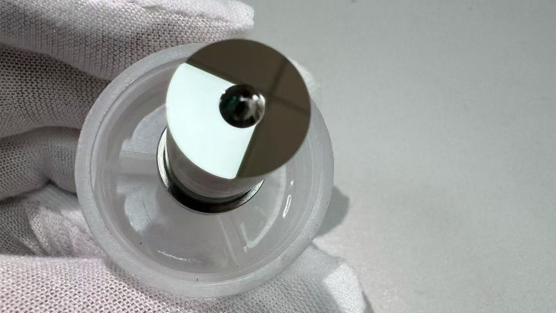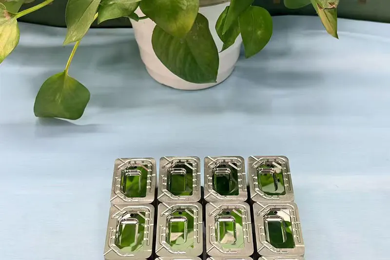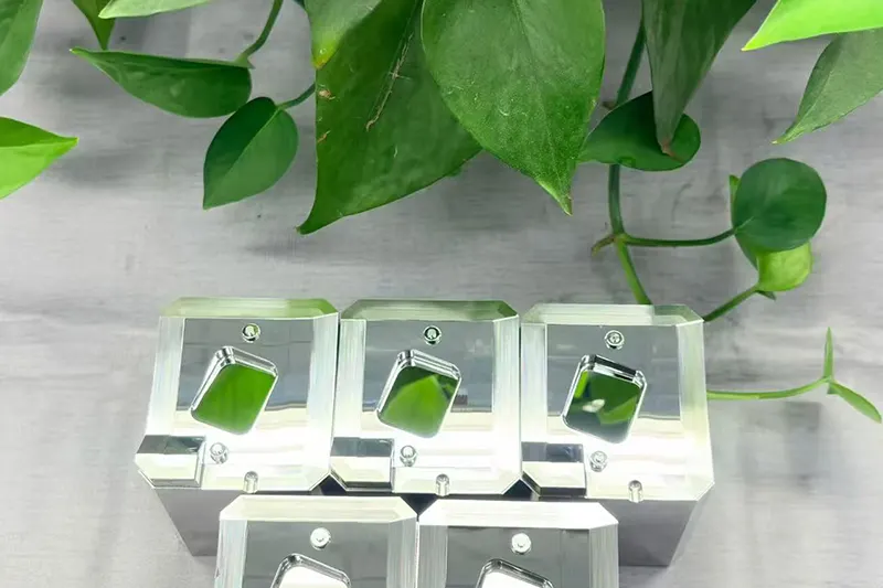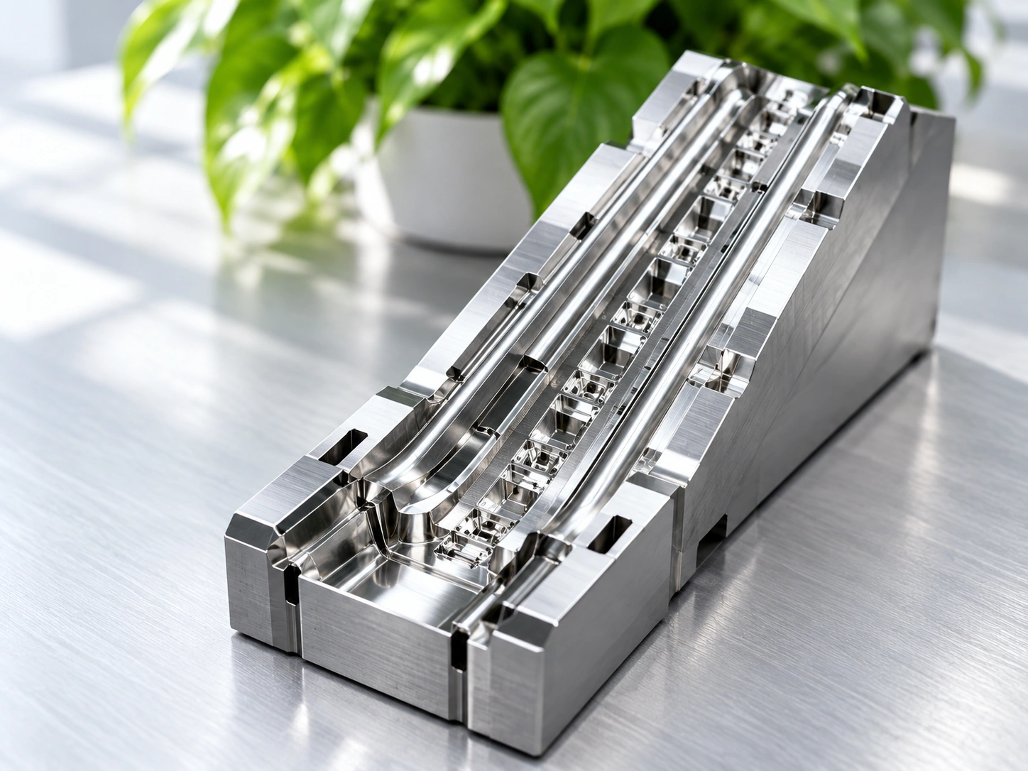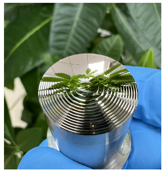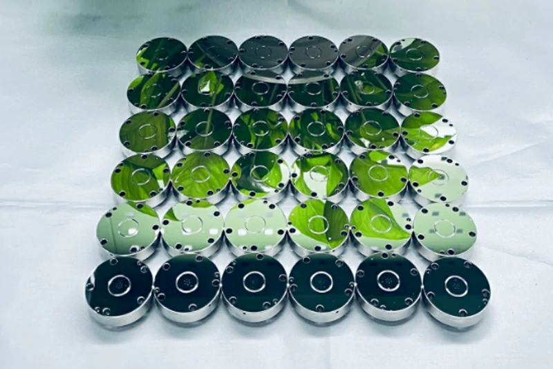
The first mirror mold insert worked perfectly.
It was installed, checked, and approved. Production continued without a problem.
Several months later, the customer needed a replacement. The new insert was made according to the same drawing, with the same specified material and tolerances.
The inspection report looked fine.
But when the toolmaker tried to install it, something was different.
The insert would not sit properly in the pocket. Or it fitted, but the working surface was slightly higher than before. In some cases, the screws could be tightened, yet the final position still did not match the original.
The immediate question was understandable:
“If both inserts meet the drawing, why can’t we simply replace one with the other?”
At YISHUN Optical, we see this as an interchangeability question, not simply a machining accuracy question.
Before deciding that a replacement is wrong, we need to understand how the original insert was located, supported, and accepted in the tool.
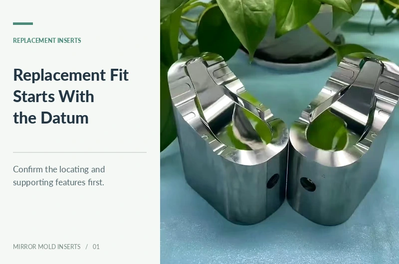
A Replacement Insert Has to Match More Than the Drawing
When an engineer designs a precision insert, the drawing defines the intended geometry.
But a replacement does not operate on its own.
It sits inside an existing pocket, contacts specific support surfaces, and is held in position by the surrounding components.
Those relationships determine whether it fits correctly.
Consider an insert with a precisely machined outer profile.
If the original pocket is slightly different from its nominal dimensions, the first insert may have been fitted or adjusted during the original assembly.
Everything works after that adjustment.
Months later, a replacement made strictly to the nominal drawing may not behave the same way.
This does not automatically mean that either insert is defective.
It may mean the design, the existing tool condition, and the actual acceptance history have not been fully connected.
For a replacement project, the approved drawing is essential, but it may not be the only information we need.

The Existing Pocket May No Longer Match Its Original Condition
One of the first things we want to understand is the condition of the tool that will receive the replacement.
Has the pocket been repaired?
Has it been cleaned with an abrasive method?
Were any support areas adjusted during maintenance?
Was the original insert fitted by hand before the tool was approved?
Over time, localized wear, damage, cleaning, or maintenance can affect how a component sits against its mating surfaces.
Even a small burr or trapped particle can prevent proper seating.
This is especially important for inserts with tightly controlled heights, narrow fitting clearances, or sensitive optical surface positions.
Imagine that the bottom support surface is intended to locate the insert at a defined height.
If the replacement contacts a raised spot instead of sitting evenly, tightening the screws may not correct the problem.
The insert can tilt, shift, or experience unwanted stress.
In that situation, removing material from the replacement without first examining the pocket may only create another problem.
We prefer to distinguish between three possibilities:
- The replacement itself has a dimensional or geometric error.
- The existing pocket or mating component differs from the nominal design.
- Both parts satisfy their individual specifications, but the combined fit is unsuitable.
These situations require different corrective actions.
Identify the Surfaces That Actually Locate the Insert
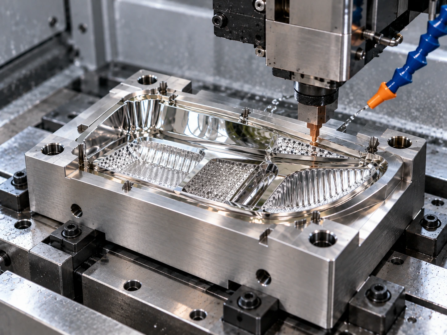
A mirror mold insert can have many precision surfaces, but they do not all serve the same purpose.
Some form the required optical or cosmetic geometry.
Others establish where the insert sits inside the tool.
For replacement work, the second group deserves particular attention.
We want to know which surface controls height, which face controls lateral position, and which feature determines orientation.
The screw holes may only provide clamping. They may not be intended to locate the insert accurately.
If the replacement relies on screw clearance to establish its position, the assembly result can vary.
A locating dowel, a side reference face, or a defined seating plane may provide the actual positioning function.
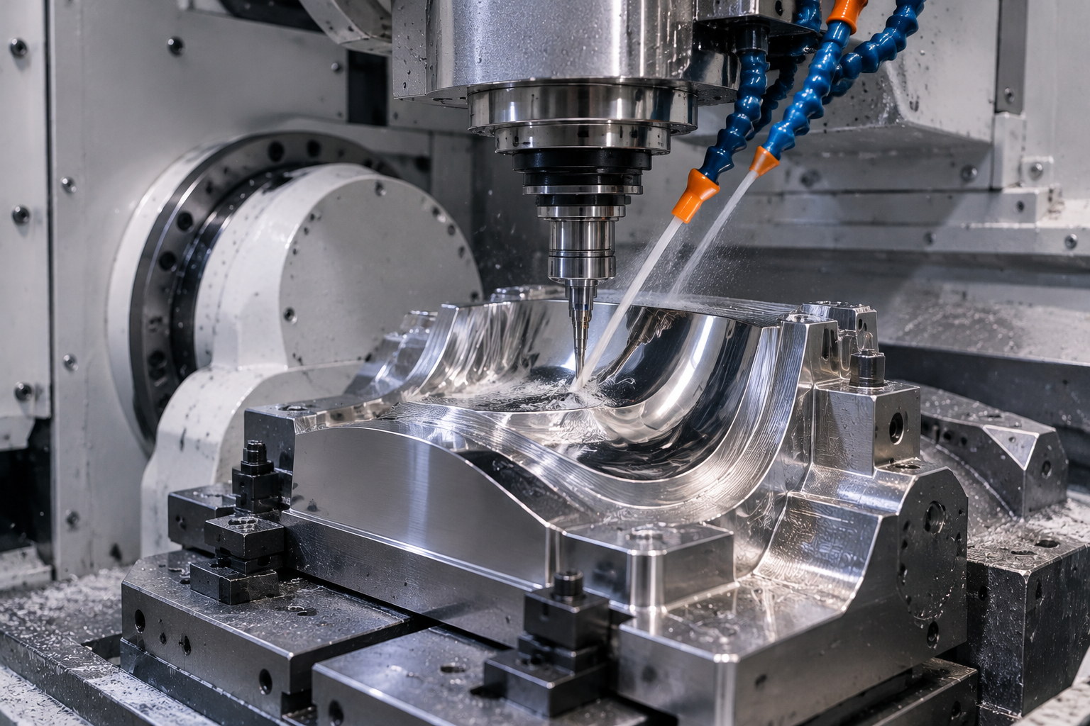
This distinction matters when planning precision CNC machining and dimensional inspection.
For example, two inserts can have the same overall height but different distances between the bottom seating plane and a critical working surface.
A simple overall-height measurement may not reveal that relationship.
The useful question is not only whether the part is within tolerance.
It is whether the important features are within tolerance relative to the datums that control installation.
Why Copying the Old Insert Is Not Always Enough
Customers sometimes send an existing insert and ask us to make an identical replacement.
An original sample can be extremely useful.
It can show details that are missing from older drawings, such as a special corner condition, a locally modified support face, or a practical mounting feature.
However, the old insert is not automatically a perfect master.
It may have experienced wear, local rework, damage, or fitting adjustments.
If we copy every measured detail without understanding its purpose, we may reproduce an unwanted condition.
For example, an unusually relieved corner may have been intentionally modified to clear the surrounding tool.
Or it may simply be damaged.
Those two possibilities should not receive the same treatment.
When the current drawing and the physical sample disagree, we would rather identify the difference and ask the customer which condition is approved.
A useful replacement review separates the following information:
| Reference | What it can tell us |
|---|---|
| Latest approved drawing | Intended dimensions, tolerances, and datum scheme |
| Existing approved insert | Actual geometry and possible fitting modifications |
| Tool pocket inspection | Current mating dimensions and physical condition |
| Original inspection records | Features verified when the first insert was accepted |
| Assembly feedback | Where the replacement contacts, shifts, or fails to seat |
No single source answers every question.
The objective is to identify which dimensions and relationships must be reproduced, and which differences require engineering approval.
Check the Drawing Revision Before Starting the Replacement
Another risk is using the wrong design revision.
A customer’s purchasing department may have the drawing from the first order.
The tool maintenance team may have a later version.
The original supplier may have produced the insert using an approved modification that was never reflected in the drawing now being circulated.
If these records are not aligned, everyone may believe they are discussing the same component while referring to different versions.
For a replacement project, we recommend confirming the drawing revision, part number, cavity or insert identification, and any approved deviations.
If the customer supplies both 2D and 3D files, they should describe the same approved geometry.
When the previous insert was modified after initial production, it is important to determine whether that modification belongs in the replacement specification.
This review may seem administrative, but it can prevent machining the wrong geometry with excellent precision.

Don’t Use the Mirror Surface to Correct a Seating Problem
Suppose the replacement insert sits slightly too high.
The working surface is mirror-finished, and the customer wants it to align with the surrounding geometry.
One possible reaction is to remove a little material from the insert.
But where should that material come from?
If the problem is the supporting face, adjusting the optical surface may destroy a feature that was already correct.
If the problem is an incorrect locating reference, changing the bottom height without understanding the assembly relationship may also be ineffective.
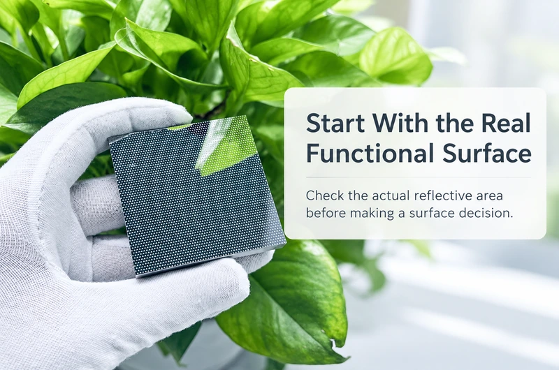
We try to separate the functional mirror surface from the mechanical surfaces responsible for installation.
The mirror area must retain its specified form and surface condition.
The seating and locating features must establish the required assembled position.
A correction should address the source of the mismatch, not simply the easiest surface to reach.
For this reason, mirror finishing and polishing should not become a general method for compensating for an incorrect mechanical fit.
On a precision insert, removing material from the wrong surface can turn a recoverable assembly issue into a more expensive replacement problem.
Measure the Relationships That Matter During Assembly
When evaluating a replacement, checking individual dimensions is necessary but may not be sufficient.
We also want to verify the relationships between the locating features and the critical working geometry.
Depending on the design, the inspection plan might include the seating plane, side references, locating holes, overall profile, and the height or position of the functional surface relative to those references.
A coordinate measuring machine may be suitable for many of these dimensional relationships.
Other features may require different measurement methods based on their size, accessibility, and specified tolerance.
For some projects, a controlled fixture or an agreed functional fit check may also be useful.
However, a supplier’s bench inspection cannot always establish how an insert will behave inside the customer’s existing tool.
That is why the customer may need to confirm final assembly fit using the actual pocket and approved installation procedure.
Inspection should provide clear evidence of what was measured, the datum system used, and the acceptance limits.
A report containing many measurements is not necessarily useful if it misses the dimension responsible for locating the part.
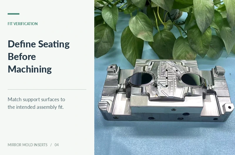
What YISHUN Needs Before Machining a Replacement Insert
For a new optical mold insert, a complete drawing package is normally the starting point.
For a replacement that must fit an existing tool, we may need additional information.
The most useful package includes the latest approved 2D and 3D files, material specification, critical tolerances, and the identification of the insert being replaced.
If the original component is available, photographs and measurement records can help.
We also want to understand whether the replacement must fit an unchanged tool pocket, whether the pocket has been repaired, and whether any previous fitting modifications were approved.
If the customer has already experienced an installation problem, a short explanation is valuable.
Does the insert stop before reaching the bottom?
Does it seat but sit too high?
Does it move when the screws are tightened?
Is the problem limited to one locating side?
These details help us focus the technical review on the actual issue.
At YISHUN Optical, our role is to evaluate the precision machining requirements, clarify critical features, and propose an inspection approach that supports the intended fit.
We cannot guarantee interchangeability with an unmeasured or modified tool pocket based on the insert drawing alone.
But we can help customers identify the information required to make that replacement more predictable.
A Successful Replacement Should Be Defined Before Machining
For many customers, the goal of ordering a spare insert is simple: remove the old component, install the new one, and return the equipment to its intended condition.
Achieving that result requires more than reproducing a polished surface.
It requires agreement on the approved design, the current mating conditions, the locating references, and the inspection evidence.
If those details are established early, the replacement can be evaluated against a clear technical target.
If they remain unclear, even a carefully machined insert can arrive and create an unexpected fitting problem.
Need a replacement mirror mold insert for an existing tool?
Send us the latest drawings, available inspection records, and information about the tool pocket or original insert.
If the previous replacement failed to fit, tell us exactly where the problem occurred.
Our engineering team can review the machining requirements and help clarify the critical dimensions before your next replacement order.