Key Takeaways
- LiDAR optics require surface roughness below Ra 1nm to minimize signal loss and false returns
- Laser damage threshold specifications demand pristine surface quality and defect-free coatings
- Multi-material manufacturing capabilities essential for complete LiDAR optical assemblies
- Scanning mirror surfaces require exceptional flatness and reflectivity for 905nm-1550nm wavelengths
- Precision polishing processes eliminate subsurface damage while achieving required surface quality
- YISHUN Optical’s ultra-precision capabilities support LiDAR optical component manufacturing
Light Detection and Ranging (LiDAR) systems have become essential sensing modalities for autonomous vehicles, providing three-dimensional environmental perception that complements camera and radar sensors. The optical components within these systems must perform with exceptional reliability under demanding automotive conditions while meeting specifications that ensure accurate distance measurement and object detection.
Understanding the surface quality requirements and manufacturing processes for LiDAR optics enables more effective collaboration between optical designers and manufacturing partners.
LiDAR System Fundamentals
LiDAR systems measure distances by emitting laser pulses and analyzing reflected returns. Key system characteristics include:
Wavelength Selection
Most automotive LiDAR systems operate at one of two wavelengths:
- 905nm: Less expensive laser sources, higher eye safety concerns, absorption by dark materials
- 1550nm: Improved eye safety allowing higher power, better performance in fog, higher component costs
The wavelength choice affects optical component specifications and material selection throughout the system.
Ranging Principle
Time-of-flight (ToF) LiDAR measures the delay between pulse emission and return detection:
- Light travels approximately 30cm per nanosecond
- Modern detectors resolve timing to picoseconds
- Optical quality directly affects achievable range and accuracy
Optical Components in LiDAR Systems
LiDAR systems comprise multiple optical subsystems, each with specific requirements:
Transmit Optics
The transmit channel shapes and directs the laser beam:
- Collimating lenses creating parallel beam profiles
- Beam steering elements for scanning systems
- Output windows maintaining beam quality
- Surface quality critical for power handling and beam profile
Receive Optics
The receive channel collects reflected light:
- Objective lenses gathering return signals
- Filters blocking ambient light
- Detector windows with anti-reflection coatings
- Sensitivity demands the same quality as transmit optics
Scanning Mechanisms
Mechanical and solid-state scanning systems include:
- Rotating mirrors with ultra-flat reflective surfaces
- Polygon scanners for high-speed operation
- MEMS mirrors enabling compact form factors
- Galvanometer scanners for precision pointing
Surface Quality Impact on LiDAR Performance
Surface quality directly affects LiDAR system performance through several mechanisms:
Light Scatter Losses
Surface roughness causes light scatter that degrades system performance:
- Scatter reduces effective transmit power
- Return signal scatter decreases SNR
- Surface scatter can create false returns
- Sub-nanometer roughness minimizes these effects
Signal-to-Noise Ratio Effects
The signal-to-noise ratio determines detection capability:
- Higher SNR enables longer detection ranges
- Surface quality contributes to total noise budget
- Scatter creates background that masks weak returns
- Clean surfaces maximize signal collection
Laser Damage Threshold
High-power laser operation requires pristine surfaces:
- Surface defects concentrate optical energy
- Localized heating can damage coatings and substrates
- Defect-free surfaces handle higher peak powers
- Surface inspection critical for high-power systems
Surface Roughness Specifications
LiDAR optics require surface roughness specifications that exceed many conventional applications:
Specification Requirements
Typical specifications for LiDAR optical surfaces:
| Component Type | Surface Roughness | Manufacturing Process |
|---|---|---|
| Transmit collimators | Ra < 0.5nm | Super-polishing |
| Receive objectives | Ra < 1nm | Precision polishing |
| Scanning mirrors | Ra < 1nm | Diamond turning or polishing |
| Window elements | Ra < 1nm | Precision polishing |
| Filter substrates | Ra < 1nm | Super-polishing |
Measurement Methods
Surface roughness measurement employs specialized techniques:
- Atomic Force Microscopy (AFM): Direct measurement of nanoscale features
- White Light Interferometry: Non-contact surface profiling
- Phase Shift Interferometry: High-resolution surface mapping
- Total Integrated Scatter (TIS): Indirect assessment via scatter measurement
Manufacturing Processes for LiDAR Optics
Achieving the required surface quality requires sophisticated manufacturing processes:
Diamond Turning
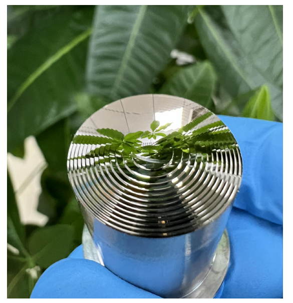
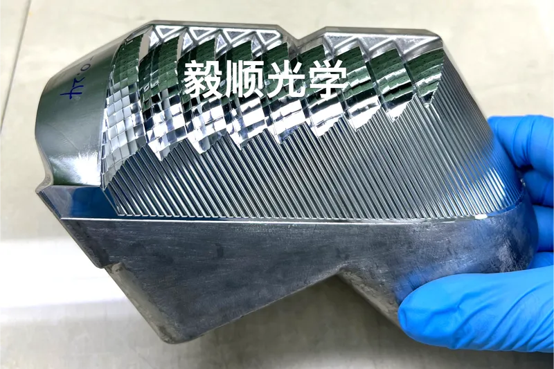
Single Point Diamond Turning (SPDT) produces surfaces approaching required quality:
- Directly achievable Ra below 1nm for some materials
- Eliminates traditional grinding and polishing steps
- Excellent form accuracy (typically ±0.5μm)
- Limited to non-ferrous and soft materials
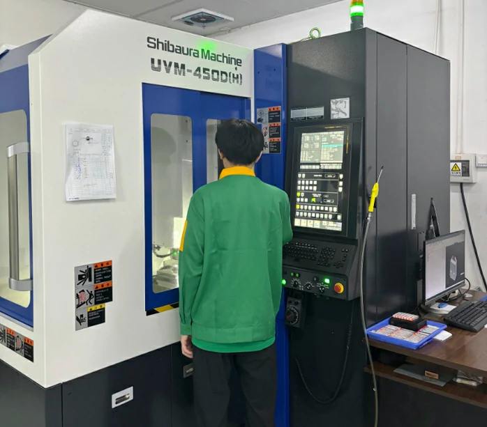
The Moore Nanocenter and similar ultra-precision machines enable direct production of optical-quality surfaces on aluminum, copper, brass, and certain plastics.
Precision Polishing
Traditional optical polishing remains relevant for many LiDAR optics:
- Pitch polishing for final figure correction
- Computer-controlled polishing (CCP) for complex surfaces
- Magnetorheological finishing (MRF) for sub-nanometer surfaces
- Ion beam figuring for ultimate precision
Super-Polishing Processes
Meeting sub-nanometer requirements often requires super-polishing:
- Ion beam polishing removes material at atomic levels
- Plasma polishing uses activated gas species
- Elastic emission machining (EEM) combines chemical and mechanical effects
- These processes eliminate subsurface damage while achieving required smoothness
Material Considerations for LiDAR Optics
Material selection affects achievable surface quality and optical performance:
| Material | LiDAR Applications | Surface Quality Achievable |
|---|---|---|
| Aluminum alloys | Scanning mirrors, mounts | Ra < 1nm via diamond turning |
| Glass (B270, BK7) | Lenses, windows | Ra < 1nm with super-polishing |
| Germanium | IR optics (1550nm systems) | Specialized processes required |
| Sapphire | Durable windows | Ra < 1nm achievable |
| Fused silica | UV-compatible optics | Ra < 1nm with super-polishing |
| PMMA/PC | Lightweight optics, covers | Ra < 1nm via diamond turning |
Coating Requirements for LiDAR Optics
Coatings enhance optical performance but introduce their own requirements:
Anti-Reflection Coatings
Multi-layer AR coatings reduce reflection losses:
- Typical reflectance < 0.5% per surface
- Broad wavelength coverage for laser sources
- Durable enough for automotive environments
- Adhesion requires surface roughness below Ra 1nm
High-Reflector Coatings
Scanning mirrors require high-reflectance coatings:
- 99% reflectance typical for laser mirrors
- Wavelength-specific optimization for 905nm or 1550nm
- Laser damage threshold exceeding system peak power
- Stress-controlled application preventing distortion
Narrowband Filters
Wavelength-selective filters block ambient light:
- High transmission at laser wavelength
- Deep blocking outside passband
- Angle-of-incidence tolerance considerations
- Temperature stability for automotive operation
Subsurface Damage Considerations
Traditional grinding processes introduce subsurface damage affecting performance:
Damage Mechanisms
Grinding creates subsurface cracks and stress:
- Crack depths typically measured in microns
- Damage creates scatter sites and stress concentrations
- Super-polishing can remove but not eliminate damage
- Diamond turning often avoids this issue entirely
Detection Methods
Subsurface damage requires specialized detection:
- Etch pit counting after material removal
- Cross-sectional microscopy
- Ultrasound velocity mapping
- Scatter measurement sensitivity
Environmental Requirements
Automotive LiDAR components face demanding environmental conditions:
Temperature Range
Operation across wide temperature ranges:
- Storage: -40°C to +85°C
- Operating: -40°C to +70°C typical
- Thermal cycling affecting coating adhesion
- Material coefficient of thermal expansion considerations
Vibration and Shock
Mechanical robustness requirements:
- Vibration resistance during vehicle operation
- Shock tolerance for road conditions
- Mounting security for optical alignments
- Fatigue resistance for long lifetime
Humidity and Contamination
Environmental protection:
- Sealed optics preventing moisture ingress
- Hydrophobic coatings for external surfaces
- Contamination resistance for reliability
- Degradation monitoring capability
Quality Verification for LiDAR Optics
Comprehensive verification ensures components meet specifications:
Surface Quality Testing
- Interferometric surface figure measurement
- AFM or profilometer roughness assessment
- Visual inspection per MIL standards
- Scatter measurement verification
Optical Performance Testing
- Transmittance/reflectance verification
- Wavefront quality measurement
- Coating spectral characterization
- Laser damage threshold testing
Environmental Testing
- Thermal cycling verification
- Humidity exposure testing
- Vibration and shock testing
- Accelerated lifetime testing
Manufacturing Challenges and Solutions
Producing LiDAR optics at automotive volumes presents challenges:
Consistency Across Production
Maintaining quality across high volumes:
- Statistical process control essential
- Process capability indices (Cpk > 1.33)
- Continuous monitoring and feedback
- Automated inspection systems
Cost Management
Automotive pricing requires efficient manufacturing:
- Process optimization reducing cycle times
- Automation where feasible
- Yield improvement programs
- Material utilization optimization
Supply Chain Considerations
Long-term supply assurance:
- Supplier financial stability
- Capacity for growth requirements
- Quality system certification
- Long-term pricing commitments
Future Requirements for LiDAR Optics
LiDAR technology continues evolving, with future requirements intensifying:
Higher Resolution Systems
Solid-state and advanced scanning systems:
- More measurement points requiring multiple optical channels
- Higher frame rates demanding faster scanning
- Improved angular resolution for better object discrimination
Eye-Safety at Higher Powers
Longer detection ranges require higher power:
- Pristine surfaces essential for power handling
- Enhanced coating durability requirements
- Stricter surface defect limits
Cost Reduction Pressure
Consumer vehicle deployment demands lower costs:
- Manufacturing efficiency improvements
- Simplified optical designs
- Higher yields and throughput
- Optimized material usage
Conclusion
LiDAR optics manufacturing requires surface quality and precision that push the boundaries of conventional optical manufacturing. The combination of sub-nanometer surface roughness, micrometer-level tolerances, demanding coating requirements, and automotive environmental robustness creates challenges that only specialized manufacturers can address effectively.
Understanding these requirements enables product designers to make informed decisions about optical specifications and manufacturing approaches. Close collaboration between optical designers and manufacturing engineers from early program stages ensures that designs are both optically optimal and producible at target costs and volumes.
Frequently Asked Questions
What surface roughness is required for LiDAR optics?
LiDAR optics typically require surface roughness below Ra 1nm to minimize signal losses from light scatter and ensure reliable laser damage thresholds for high-power operation.
How does surface quality affect LiDAR range performance?
Surface scatter reduces effective transmit power and return signal strength. Surfaces exceeding Ra 1nm roughness can significantly reduce detection range and signal-to-noise ratio.
What wavelengths are used for automotive LiDAR?
Most automotive LiDAR systems operate at either 905nm (common in current systems) or 1550nm (offering better eye safety and fog performance). Optical components must be optimized for the specific wavelength.
Can diamond turning meet LiDAR surface quality requirements?
Diamond turning can achieve Ra below 1nm on suitable materials (aluminum, brass, certain plastics), making it viable for many LiDAR optical components. Some materials and applications may require subsequent polishing.
What coating requirements exist for LiDAR optics?
LiDAR optics typically require anti-reflective coatings with <0.5% reflectance and high-reflector coatings exceeding 99% reflectance, both optimized for specific laser wavelengths.
How does automotive environment affect LiDAR optics requirements?
Automotive LiDAR must operate across -40°C to +70°C, survive vibration and shock, and maintain performance through humidity and thermal cycling. These requirements affect material selection, coating durability, and mounting design.
What quality verification is required for LiDAR optical components?
Verification includes surface roughness measurement (interferometry, AFM), transmittance/reflectance testing, laser damage threshold testing, and environmental testing (thermal cycling, humidity, vibration).
Developing LiDAR systems requiring precision optical components? Contact YISHUN Optical at info@yishunoptical.com or visit yishunoptical.com to discuss how our ultra-precision manufacturing capabilities can support your LiDAR optical requirements.