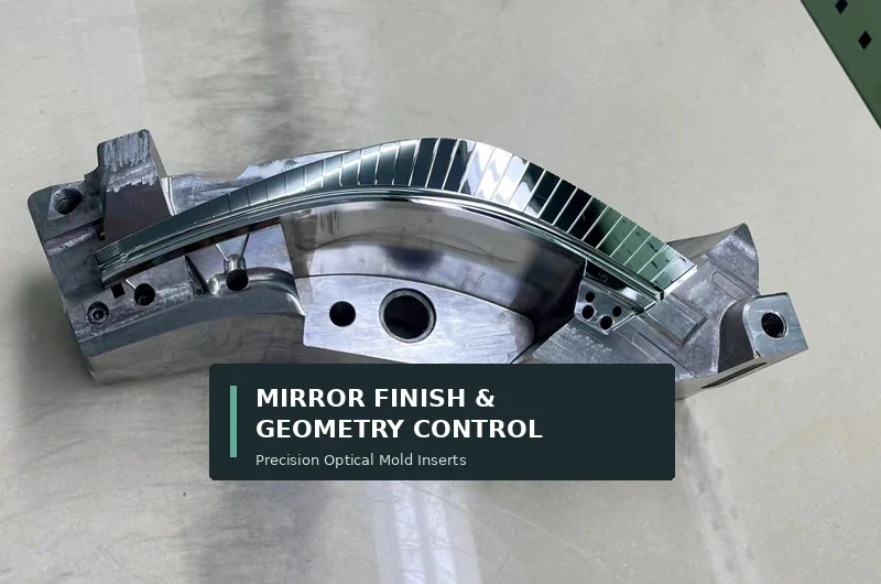
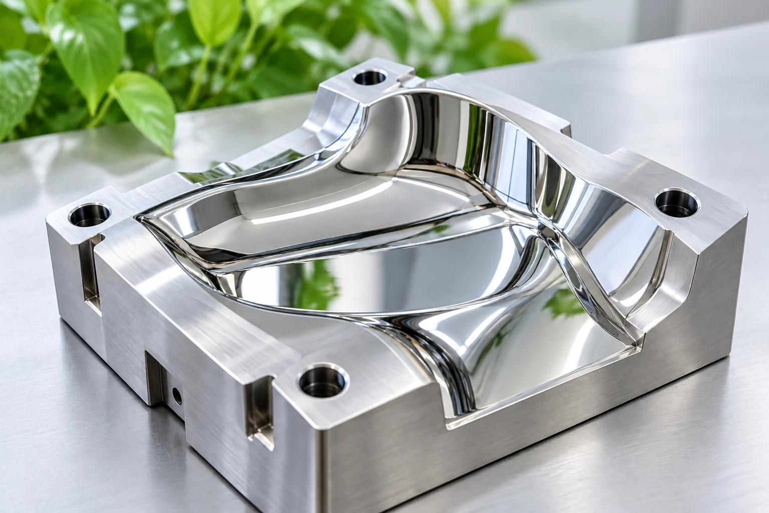
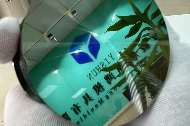
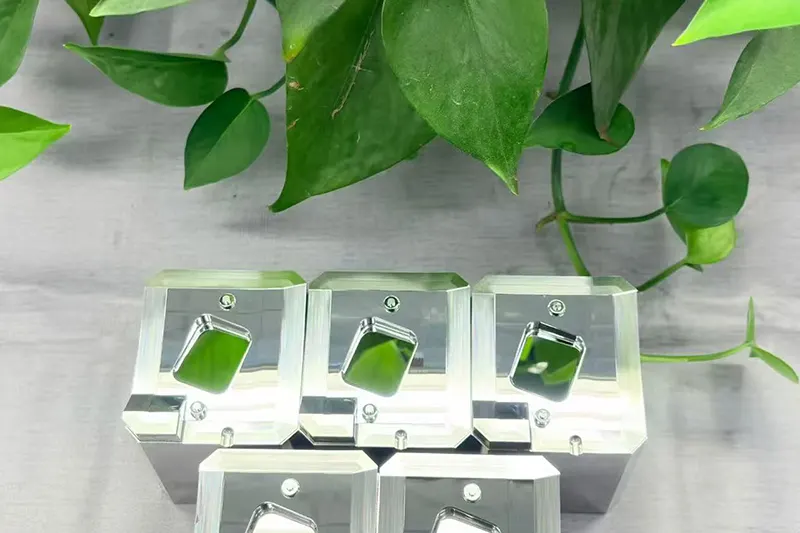
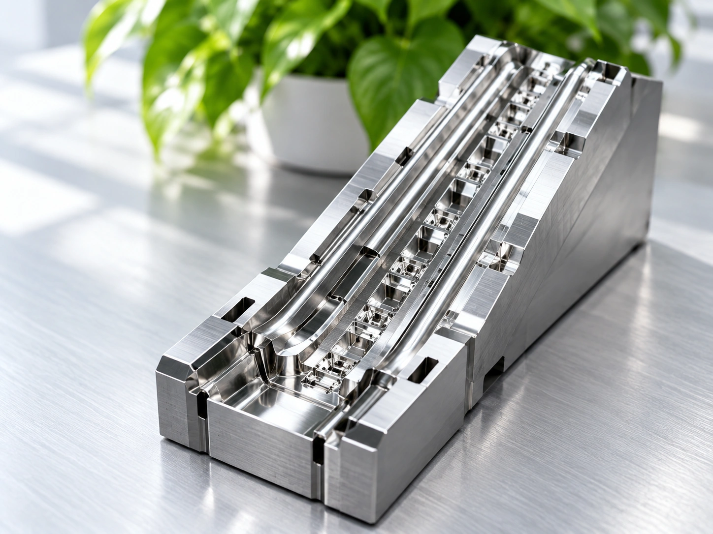
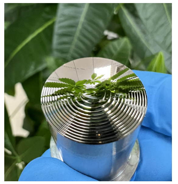
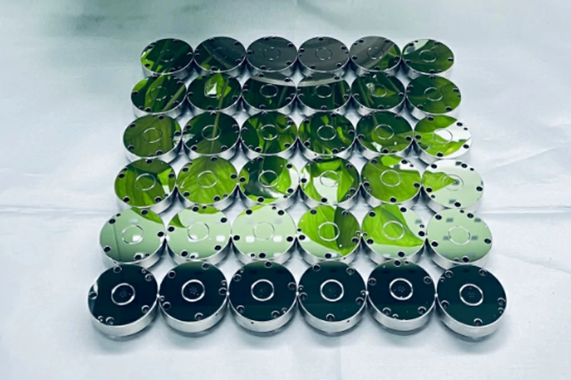
AR-HUD (Augmented Reality Head-Up Display) optical mold core machining represents the pinnacle of precision mold manufacturing, demanding freeform surface form accuracy of PV≤0.15 μm, surface roughness below Ra 0.02 μm, and the integration of ultra-precision diamond turning, slow tool servo machining, and robotic polishing within a single production workflow. This article traces the complete journey of an AR-HUD optical mold core from design validation through ultra-precision machining to mass production — addressing the unique challenges of freeform surface generation, material selection for high-volume optical polymer replication, and the quality metrology protocols that ensure consistent optical performance in the final AR-HUD system. Yishun Optical’s manufacturing infrastructure — 25 five-axis machining centers, 4 Toshiba UVM ultra-precision machines, 2 Moore diamond turning lathes (Ra≤2 nm), and an ABB robotic polishing system (±0.001 mm repeatability) — provides the complete capability set required for AR-HUD optical mold core production at automotive volumes. Contact us at yishun158@163.com or +86-755-82594863 to discuss your AR-HUD mold program.
The Evolution from Conventional HUD to AR-HUD: Manufacturing Implications
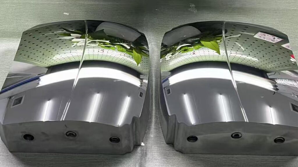
AR-HUD systems project virtual driving information at focal distances of 10–20 meters, superimposing navigation arrows, hazard warnings, and lane guidance directly onto the driver’s real-world view. This represents a fundamental shift from conventional HUD systems (which display information at 2–3 meter virtual image distance) and imposes dramatically different requirements on the optical mold that produces the AR-HUD combiner or freeform mirror.
According to Ansys’s technical documentation on Head-Up Display optical design (Ansys OpticStudio & Speos, 2024), AR-HUD systems require optical surface accuracy of PV≤0.5 μm on the image-generating elements — a 5× tighter specification than conventional HUD. This precision must be maintained across freeform mirror surfaces spanning 100–200 mm in aperture, with aspheric departure tolerances of ±0.01 mm from the theoretical surface.
The mold core that produces these AR-HUD freeform mirrors must therefore be manufactured to tolerances at least 3× tighter again, because the injection molding process introduces additional form deviation from thermal shrinkage, packing pressure effects, and mold deflection under injection pressure. Yishun Optical’s ultra-precision machining capabilities — specifically our ability to achieve PV≤0.15 μm form accuracy — provide the necessary precision margin to produce AR-HUD freeform mirrors that meet these demanding specifications in mass production.
AR-HUD Optical System Architecture and Mold Requirements
Key Optical Components in AR-HUD Systems
An AR-HUD system comprises several precision optical elements, each requiring dedicated mold tooling:
- Picture Generation Unit (PGU) — Contains the LED/laser light source and collimation optics; requires micro-precision plastic lens molds with Ra≤0.01 μm surfaces.
- Freeform Combiner Mirror — The primary optical element that reflects the projected image to the driver’s eye; requires the most demanding freeform surface mold core in the system.
- Windshield Optical Coating — Dual-layer PVB or embedded reflective coating; not a mold component but affects overall system optical performance.
- Aspheric Lens Array — Intermediate optical elements that correct aberrations introduced by the freeform mirror; requires aspheric lens molds with PV≤0.3 μm accuracy.
Research published in Optics Express (Optica Publishing Group, 2023) on AR-HUD freeform surface design demonstrates that the freeform mirror’s surface form error directly translates to virtual image distortion — a PV form error of 1 μm on the mirror surface creates approximately 0.5 arc-minute of angular error in the projected image, which at 15-meter virtual image distance translates to a positional error of approximately 130 mm. This underscores the critical importance of ultra-precision mold core machining for AR-HUD optical components.
Surface Type Comparison: Aspheric vs. Freeform
| Surface Type | Manufacturing Method | Typical Form Accuracy | Surface Roughness | Application |
|---|---|---|---|---|
| Spherical | Conventional turning/grinding | PV 0.5–2.0 μm | Ra 0.05–0.2 μm | Conventional HUD |
| Aspheric | Ultra-precision turning/milling | PV 0.1–0.5 μm | Ra 0.01–0.05 μm | PGU collimation lenses |
| Freeform | SPDT Slow Tool Servo | PV 0.05–0.3 μm | Ra 0.002–0.02 μm | AR-HUD combiner mirrors |
Ultra-Precision Machining of AR-HUD Freeform Mold Cores
Slow Tool Servo (STS) Machining
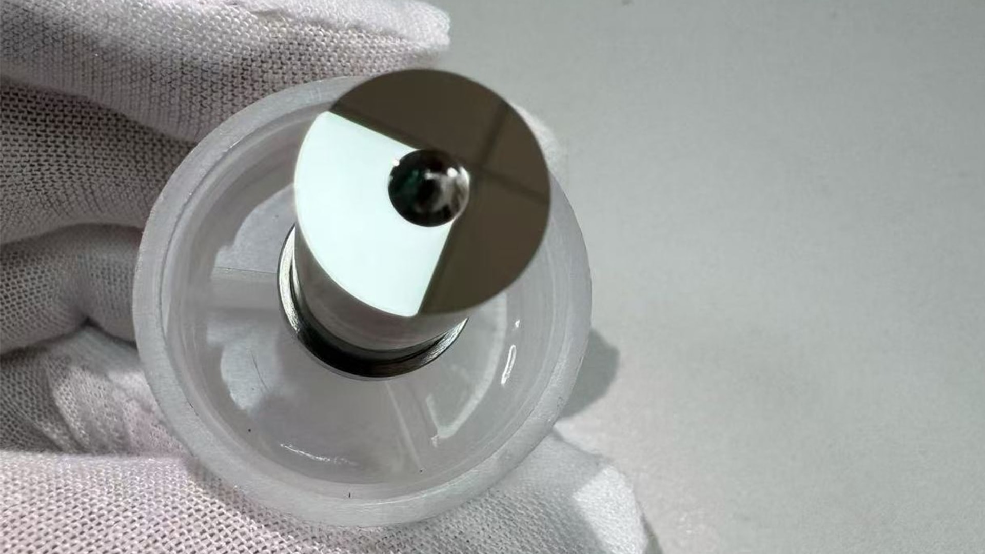
The most demanding AR-HUD freeform surface geometries require Slow Tool Servo (STS) machining on single-point diamond turning lathes. According to a study published in Precision Engineering (Elsevier, 2024), STS machining of HUD freeform mold cores achieves surface form accuracy of PV≤0.15 μm and surface roughness of Ra≤2 nm when using optimized tool path planning with cubic spline interpolation.
Yishun Optical’s Moore Nanotechnology single-point diamond turning lathes support STS machining with the following capabilities:
- Z-axis servo bandwidth: 500 Hz for high-fidelity freeform surface replication
- Air spindle speed: 0–3,000 rpm with ≤10 nm runout
- Tool nose radius: 0.5–2.0 mm single-crystal diamond tools with 10–30 nm edge radius
- Coolant: Odorless mineral spirits (OMS) for contamination-free machining
- Measurement integration: In-process surface form measurement with sub-micron accuracy
Hybrid Trajectory Planning for AR-HUD Freeform Surfaces
Yishun Optical’s engineering team has developed a hybrid trajectory planning method combining equidistant projection and cubic spline interpolation for AR-HUD freeform mold core machining. This approach ensures:
- Tool path smoothness — Cubic spline interpolation eliminates discontinuities in the tool motion that would create surface ripples
- Machining efficiency — Equidistant projection optimizes cutting time while maintaining surface form accuracy
- Vibration suppression — Feed rate modulation based on surface curvature reduces Z-axis vibration effects
Research from a 2024 published study on ultra-precision machining of HUD freeform surfaces (Nanomanufacturing and Metrology, Springer) demonstrates that Z-axis vibration is the dominant error source in STS machining, with vibration amplitudes of 50 nm producing measurable surface waviness at spatial frequencies of 0.1–1.0 mm⁻¹. Yishun Optical addresses this through real-time vibration monitoring and adaptive cutting parameter optimization.
Five-Axis Machining of AR-HUD Mold Cavities
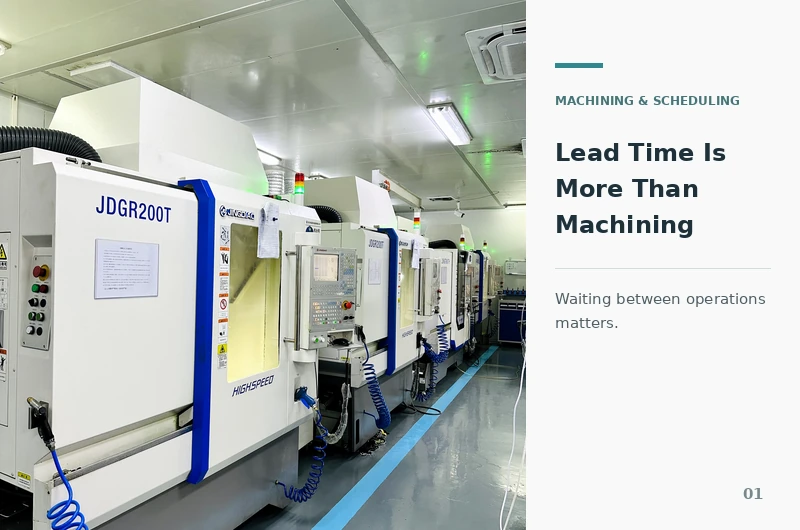
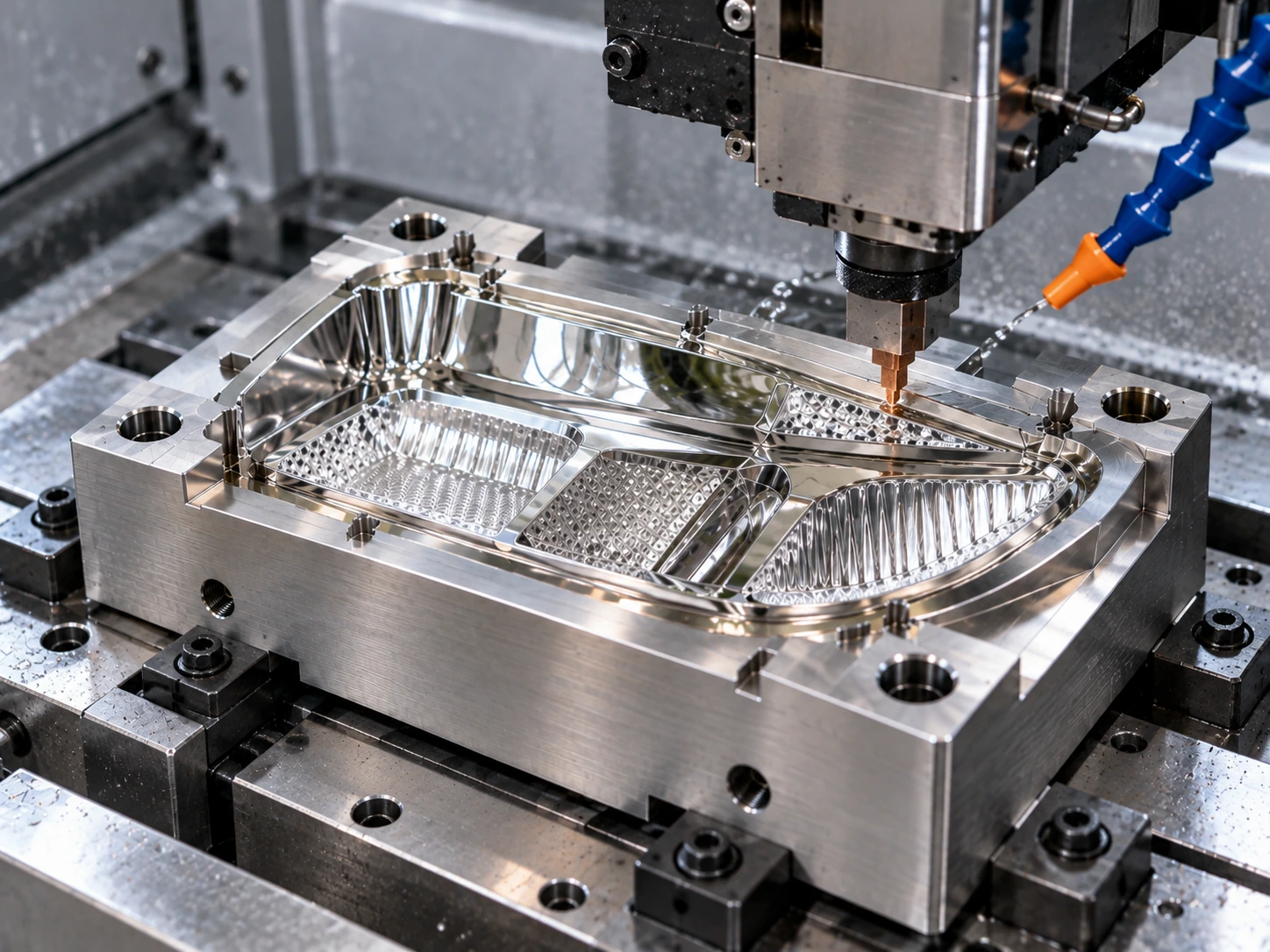
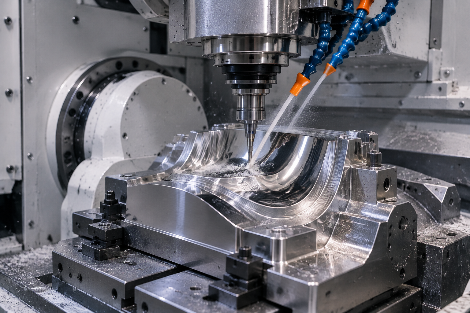
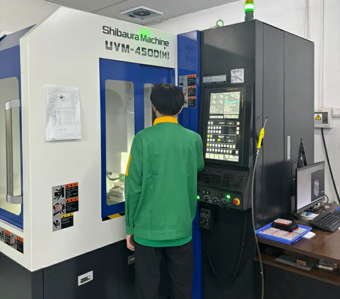
For AR-HUD mold cores with complex 3D geometries requiring multi-axis machining, Yishun Optical’s 25 five-axis machining centers — including Röders RXP500DS and Roku Roku precision machines — achieve:
- Positional accuracy: ±0.002 mm (Fanuc/Heidenhain control systems)
- Surface form accuracy: PV≤0.15 μm on freeform surfaces up to 300 mm aperture
- Surface finish: Ra≤0.02 μm through systematic HSM + precision grinding + robotic polishing workflow
- Material flexibility: Aluminum (prototype), tool steel S136H/H13 (production), beryllium copper (high-volume)
Mold Steel Selection for AR-HUD Optical Mold Cores
| Steel Grade | Application | Key Advantage | Machining Method |
|---|---|---|---|
| Aluminum 7075-T6 | Rapid prototype tooling | Fast machining, low cost | 5-axis HSM |
| S136H (ESR) | Production mold cores (PC, COP) | High polishability, corrosion-resistant | SPDT + polishing |
| Beryllium Copper C17200 | High-volume production | Superior thermal conductivity | EDM + polishing |
| NAK80 | Medium-volume production | Pre-hardened, mirror-finish capable | 5-axis HSM + polishing |
From Design Validation to Mass Production: The Complete Workflow
Phase 1: Optical Design Translation
The AR-HUD freeform surface design — typically generated in Zemax OpticStudio, CODE V, or Synopsys Speos — must be translated into machine-readable tool path data. Yishun Optical’s engineering team performs:
- Surface data import and verification — CL data (Cutter Location) import from optical design software with verification against design intent
- Machinability analysis — Evaluation of minimum feature size, undercut geometry, and parting line optimization
- Tool path generation — CAM programming using Siemens NX or Mastercam with adaptive clearing strategies
- Mold flow simulation — Moldex3D analysis of filling, packing, and warpage for the AR-HUD optical component
Phase 2: Prototype Mold and Design Validation
According to Ansys Speos HUD optical analysis protocols (2024), the complete AR-HUD optical validation requires testing against five performance metrics:
- Virtual image distance (VID) — Must match design specification ±5%
- Field of view (FOV) — Horizontal ≥6°, vertical ≥3° for AR applications
- Eye Motion Box (EMB) — Must accommodate ±50 mm horizontal and ±25 mm vertical driver movement
- Image brightness — ≥12,000 cd/m² for daylight legibility
- MTF (Modulation Transfer Function) — ≥30% at 30 lp/mm across full field of view
Yishun Optical produces prototype aluminum mold inserts within 2–3 weeks for optical and dimensional validation, enabling rapid iteration of the AR-HUD optical design before committing to production steel tooling. This approach reduces tooling revision cycles by 40–50% compared to traditional steel-first tooling strategies.
Phase 3: Production Mold Fabrication
Full production tooling for AR-HUD optical mold cores follows a rigorous multi-stage process:
- Rough machining — 5-axis HSM at 40,000–60,000 rpm, removing 90% of material while maintaining form accuracy within ±0.02 mm
- Semi-finish machining — Precision HSM reducing scallop height to <0.001 mm
- Stress relief heat treatment — Critical for steel molds to eliminate machining-induced internal stress
- Ultra-precision finishing — SPDT diamond turning (Ra≤2 nm) or precision grinding (Ra≤0.02 μm) to achieve final optical surface
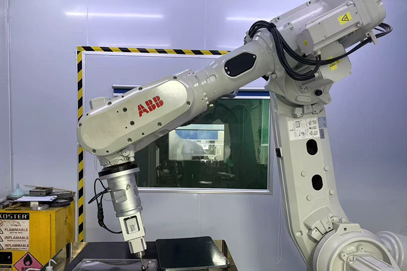
- Robot-assisted polishing — ABB 6-axis robotic polishing system with ±0.001 mm repeatability for consistent surface quality across complex freeform geometries
- Interferometric verification — Zygo interferometer testing with λ/20 accuracy for full-aperture surface form measurement
- CMM dimensional verification — All critical dimensions verified against design specifications
Phase 4: Mass Production and Process Control
AR-HUD optical components require injection molding process control far more stringent than conventional plastic parts:
- Mold temperature control: ±0.5°C uniformity across cavity surface (achieved through precision cooling channel design)
- Material drying: 4–6 hours at material-specific temperature for optical polymers (PC, COP, PMMA)
- Injection speed: Segmented profile (5–20 mm/s → 80–150 mm/s → deceleration) to minimize weld lines
- Pack pressure: 100–150 MPa with gradient reduction to minimize residual stress
- In-process monitoring: Vision inspection and CMM sampling of every 100th part for critical dimensions
Yishun Optical’s Class 10 cleanroom for optical component molding ensures that AR-HUD optical parts are produced without particulate contamination that could create scatter centers in the optical system.
Material Considerations for AR-HUD Optical Components
Optical-Grade Polycarbonate for AR-HUD Mirrors
Polycarbonate is the dominant material for injection-molded AR-HUD freeform mirrors due to its high impact resistance, dimensional stability across −40°C to +85°C automotive temperature cycles, and optical clarity. However, polycarbonate’s high melt viscosity requires careful gate design and mold temperature optimization.
According to Moldflow analysis published in SPIE Conference Proceedings (Chen & Tang, 2010, DOI: 10.1117/12.861146), gate location significantly affects the residual stress distribution in injection-molded HUD aspheric projector lenses. Optimal gate design reduces weld line formation near the optical center and minimizes flow-induced birefringence by aligning the polymer flow direction with the optical axis.
Cyclic Olefin Polymer (COP) for High-Performance AR-HUD
COP (TOPAS® and ZeonorFilm® grades) offers superior optical properties for AR-HUD applications — lower moisture absorption (0.01% vs. 0.15% for PC), minimal birefringence, and better thermal dimensional stability. For AR-HUD systems requiring maximum optical performance, COP is increasingly specified despite its higher material cost.
Surface Coating Compatibility
AR-HUD freeform mirrors frequently require vacuum-deposited aluminum coatings with SiO₂ protective overcoat to achieve the ≥90% reflectance required for adequate virtual image brightness. The mold surface finish directly affects coating adhesion and uniformity — Yishun Optical specifies Ra≤0.02 μm with no visible tool marks or scratches on all AR-HUD mold cavity surfaces before coating qualification.
Quality Metrology for AR-HUD Optical Mold Cores
Interferometric Surface Form Measurement
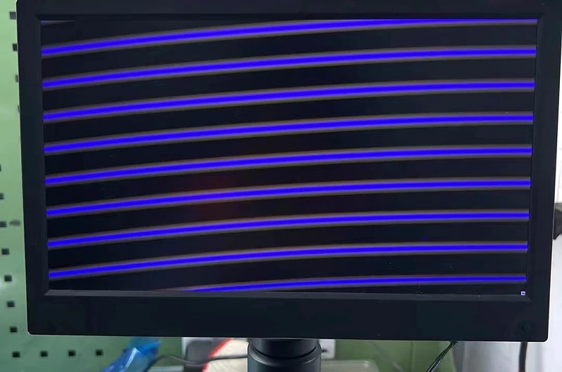
Full-aperture interferometric testing using Zygo or Moiré interferometers provides surface form accuracy data with measurement uncertainty below λ/20 (approximately 32 nm at λ=632.8 nm). Yishun Optical’s metrology lab performs interferometric testing on all AR-HUD mold cores with apertures up to 300 mm, generating comprehensive surface accuracy reports including PV (Peak-to-Valley), RMS (Root Mean Square), and Seidel aberration decomposition.

Surface Roughness Measurement Protocol
Surface roughness is characterized across three spatial frequency bands:
- Form error (low frequency): Zygo interferometer, measured as PV and RMS over the full aperture
- Waviness (medium frequency): Talysurf contact profilometer, cutoff wavelength 0.08–2.5 mm
- Roughness (high frequency): Atomic Force Microscopy (AFM) for Ra<0.1 μm surfaces
According to ISO 10110-5 specifications for optical elements, AR-HUD mirrors require surface roughness corresponding to scratch-dig 10-5 (no defects larger than 0.01 mm visible at specified illumination). Yishun Optical achieves this specification through systematic post-machining polishing and 100% visual inspection under 10× magnification.
FAQ: AR-HUD Optical Mold Core Machining
Q1: What form accuracy can Yishun Optical achieve on AR-HUD freeform mold cores?
A: Yishun Optical achieves PV≤0.15 μm form accuracy on AR-HUD freeform mold cores through a combination of Moore SPDT slow tool servo machining and systematic post-machining polishing. This exceeds the PV≤0.5 μm requirement for AR-HUD mirrors by a 3× safety margin.
Q2: What is the maximum aperture for AR-HUD freeform mirror molds at Yishun Optical?
A: Our ultra-precision machining infrastructure accommodates freeform mirror mold cores up to 300 mm aperture with PV≤0.15 μm form accuracy. The most common AR-HUD mirror size range is 80–150 mm diameter.
Q3: How does Yishun Optical handle the tool path planning for complex AR-HUD freeform surfaces?
A: Yishun Optical uses a hybrid trajectory planning method combining equidistant projection and cubic spline interpolation for AR-HUD freeform mold core machining. This approach optimizes tool path smoothness and machining efficiency while suppressing Z-axis vibration effects that cause surface waviness.
Q4: What materials do you recommend for AR-HUD mirror injection molding?
A: For standard AR-HUD applications, optical-grade polycarbonate (Makrolon® 2405 or equivalent) is recommended. For maximum optical performance with minimal birefringence, cyclic olefin polymer (COP) grades such as TOPAS® 5013 are preferred. PMMA is suitable for cover lens elements requiring maximum transmittance.
Q5: What is the typical lead time for an AR-HUD optical mold from concept to production approval?
A: Prototype aluminum tooling requires 2–3 weeks for design validation. Full steel production tooling requires 10–14 weeks depending on complexity, followed by 3–5 weeks for PPAP/PPF approval including optical performance testing.
Q6: How does Yishun Optical verify AR-HUD mold surface quality before shipment?
A: Every AR-HUD mold core undergoes full-aperture interferometric testing (PV, RMS), Talysurf surface roughness measurement (Ra, Rz), CMM dimensional verification, and 100% visual inspection under 10× magnification. All metrology is performed in temperature-controlled (20°C ± 0.5°C) metrology rooms.
Q7: Does Yishun Optical provide optical coating qualification support for AR-HUD mirrors?
A: Yes. Yishun Optical provides polished and verified mold cavity surfaces optimized for vacuum-deposited aluminum and SiO₂ coatings. We can also provide prototype parts for coating trials and optical performance validation before production tooling approval.
Conclusion
AR-HUD optical mold core machining occupies the most demanding tier of precision mold manufacturing — combining the freeform surface generation of aspheric optics, the ultra-precision requirements of nanometer-scale surface quality, and the automotive production volumes that demand exceptional mold durability. The journey from optical design validation through ultra-precision machining, robotic polishing, and interferometric verification requires a manufacturing infrastructure that few mold makers possess.
Yishun Optical’s unique combination of 25 five-axis machining centers, 4 Toshiba UVM ultra-precision machines (PV≤0.15 μm), 2 Moore diamond turning lathes (Ra≤2 nm), and an ABB robotic polishing system (±0.001 mm repeatability) — supported by a Class 10 cleanroom, ISO 9001 / ISO 14001 certifications, and National High-Tech Enterprise status (2024) — positions us as the premier AR-HUD optical mold manufacturer for Tier-1 automotive suppliers worldwide. Our 20+ years of precision optical mold experience and 3,000+ mold sets delivered to global partners including Apple (Gold Supplier) provide the proven track record your AR-HUD program demands.
Ready to discuss your AR-HUD optical mold core requirements? Visit https://yishunoptical.com/ or contact our engineering team at yishun158@163.com or +86-755-82594863 for a free feasibility assessment and DFM review of your AR-HUD optical component.