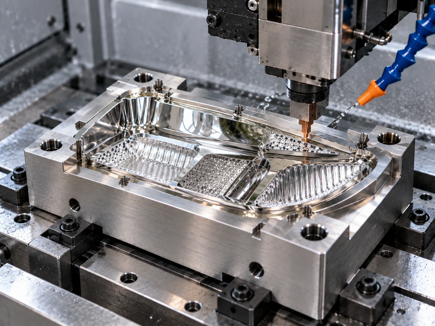
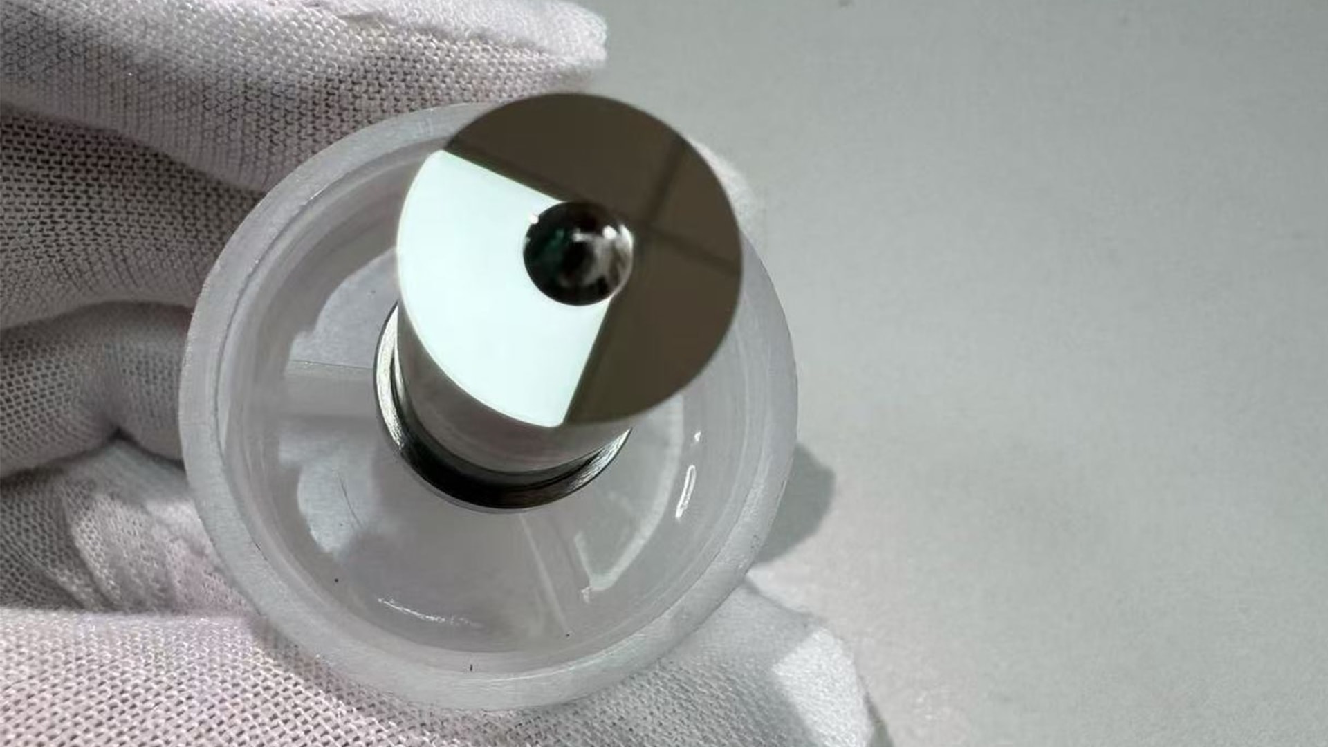
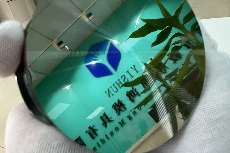
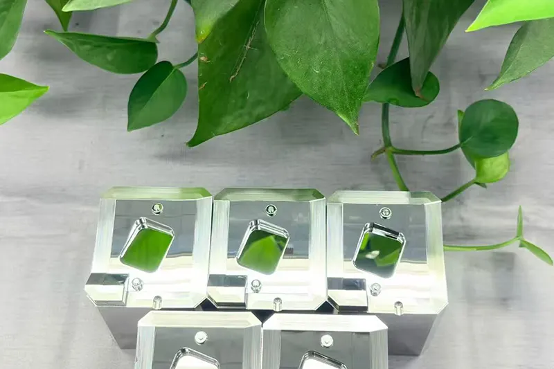
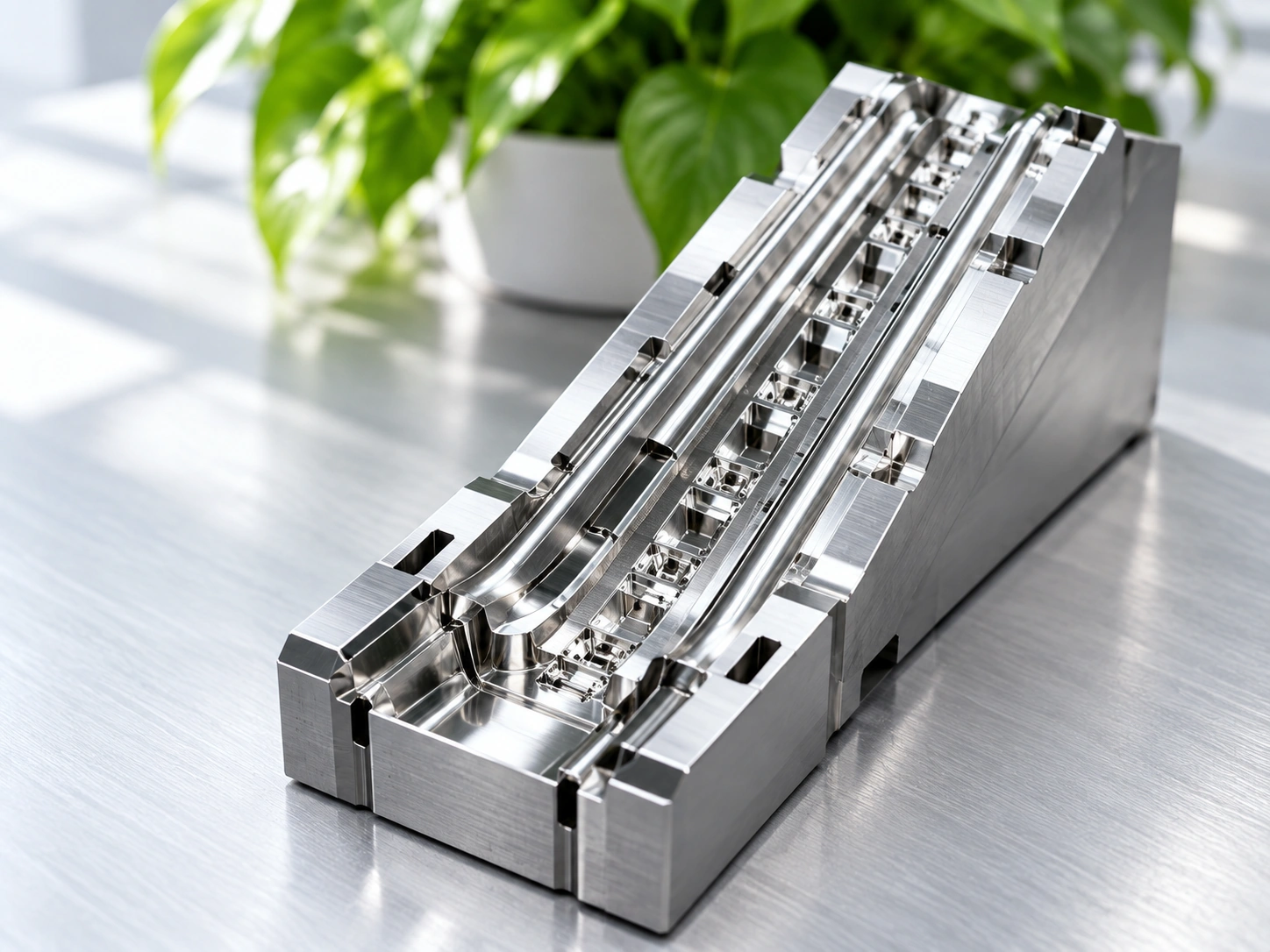
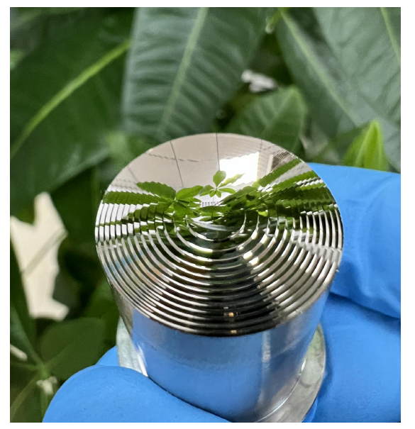
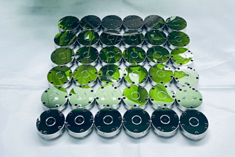
Optical polishing improves surface performance primarily by reducing microscopic roughness, processing marks, and localized defects that scatter light away from its intended path.
For transmissive components, a smoother surface can reduce scattering and help more usable light continue through the component in the intended direction. For reflective surfaces, reduced roughness can improve specular reflection by limiting the amount of light redirected into unwanted angles.
Optical polishing does not create transmission or reflection by itself; it improves the surface condition so that less optical energy is lost to unwanted scattering and surface-related defects.
The final optical performance still depends on other factors, including the material, wavelength, component geometry, surface form, contamination, and any coating applied to the surface.
Understanding these relationships helps engineers specify realistic polishing requirements instead of simply requesting the lowest possible roughness.
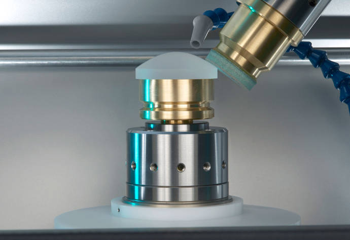
Think of Optical Performance as an Energy Distribution Problem
When light reaches an optical surface, several things can happen.
Part of the light may:
- Pass through the component;
- Reflect from the surface;
- Scatter in unintended directions;
- Be absorbed by the material or surface;
- Be redirected by imperfections in the surface geometry.
Polishing mainly addresses the surface-related contribution to this behavior.
A rough or damaged surface contains microscopic peaks, valleys, scratches, pits, and processing marks. These features disturb the direction in which light travels.
A well-controlled polishing process progressively reduces these irregularities and produces a more uniform optical interface.
The result is not simply a shinier appearance.
The important improvement is that the surface behaves more predictably.
Surface Finish Is More Than Visual Appearance
A surface can look glossy to the human eye while still being unsuitable for a precision optical application.
Human vision cannot directly evaluate nanometer-scale surface texture.
This is why optical surface performance is normally described using measurable characteristics such as:
- Surface roughness;
- Surface form;
- Flatness;
- Waviness;
- Scratch-dig or other surface imperfections;
- Dimensional accuracy.
Each describes a different type of error.
| Surface Characteristic | What It Describes | Possible Performance Effect |
| Roughness | Microscopic peaks and valleys | Increased scatter and reduced clarity |
| Flatness / form | Overall geometric deviation | Wavefront or directional error |
| Waviness | Intermediate-scale surface variation | Stray light or non-uniform optical response |
| Scratches and pits | Localized surface defects | Local scatter and cosmetic defects |
| Contamination | Residue, particles or films | Scatter, absorption or coating problems |
| Edge defects | Chips or damaged boundaries | Handling and assembly problems |
This distinction is important because polishing parameters should be selected according to the actual performance problem.
How Surface Roughness Affects Light
Surface roughness represents high-frequency microscopic variation in surface height.
When these variations become significant relative to the wavelength of the light being used, the surface can redirect more light away from the intended optical path.
Instead of maintaining clean transmission or mirror-like reflection, part of the light becomes scattered.
This can appear as:
- Haze;
- Reduced image contrast;
- Background light;
- Lower useful transmission;
- Lower specular reflection;
- Reduced measurement sensitivity;
- Non-uniform optical output.
As surface roughness decreases, surface-related scattering generally decreases, provided the material, geometry and other optical conditions remain comparable.
This is one of the main reasons why precision optical polishing focuses on measurable surface roughness rather than visual shine alone.
How Optical Polishing Can Improve Transmission
For a transparent component, transmission describes how much light passes through it.
However, there is an important distinction between total transmitted light and useful transmitted light.
A rough surface may still allow light to cross the material boundary, but some of that light can be redirected through scattering.
As a result, the component may show:
- Reduced clarity;
- Haze;
- Lower image contrast;
- Unwanted background illumination;
- Less light reaching the intended location.
Polishing reduces microscopic surface irregularities and therefore helps reduce this scattering contribution.
What Polishing Changes
A controlled polishing process can:
- Remove fine grinding marks;
- Reduce microscopic peaks and valleys;
- Remove some shallow surface defects;
- Produce a more uniform interface;
- Improve surface consistency across the optical area.
The resulting surface allows light to travel through the component with less surface-induced deviation.
For transmissive parts, polishing primarily improves useful optical transmission by reducing scattering rather than by changing the intrinsic transparency of the material.
This distinction matters during design.
If a material strongly absorbs a particular wavelength, polishing cannot remove that bulk-material absorption.
Likewise, surface reflection at an uncoated interface still exists even when the surface is extremely smooth.
What Else Determines Optical Transmission?
Transmission depends on several variables beyond surface roughness.
| Factor | Effect on Transmission | Can Polishing Directly Change It? |
| Surface roughness | Can increase scattering | Yes, substantially |
| Surface scratches | Can redirect light locally | Often |
| Material absorption | Removes energy inside the material | No |
| Material thickness | Influences total absorption | No |
| Refractive index | Influences interface reflection | No |
| Surface contamination | Can scatter or absorb light | Cleaning helps |
| Coating | Can reduce or control interface reflection | Separate process |
| Surface form | Can redirect transmitted light | Polishing may help depending on process |
Therefore, if a component has poor measured transmission, polishing should not automatically be assumed to be the only solution.
The source of the loss must first be identified.
Why Reflection Also Depends on Surface Finish
For a reflective surface, engineers often care about specular reflection—light reflected in a controlled direction.
An ideally smooth surface directs reflected light according to the geometry of the surface.
A rough surface behaves differently.
Microscopic variations create many slightly different local surface orientations. Instead of all reflected light remaining in the desired direction, some is redirected.
This produces scattered reflection.
The surface may still have high total reflectance, but less of the reflected energy may remain inside the useful specular path.
Precision polishing improves reflective performance mainly by reducing the surface features that convert controlled reflection into unwanted scattered reflection.
This is particularly important for:
- Precision mirrors;
- Reflective measurement components;
- Imaging systems;
- Optical scanning components;
- Reflective mold surfaces;
- High-accuracy optical instruments.
Polishing Does Not Determine Reflectivity Alone
For an uncoated surface, the fundamental reflection behavior also depends on the optical properties of the materials at the interface.
For a coated reflective component, the coating design can become the dominant factor controlling reflectivity.
Polishing provides the surface foundation.
A poor substrate surface can limit final performance because roughness, scratches, pits, or contamination may remain underneath or affect the subsequent coating.
However, an extremely smooth surface does not automatically produce a desired reflectivity value without considering the complete optical structure.
This leads to an important engineering distinction:
Polishing controls surface quality; material and coating design control additional parts of the optical response.
Why Surface Preparation Matters Before Coating
Many optical components receive a coating after polishing.
The quality of the underlying substrate affects how consistently the coating can be deposited.
Surface problems may include:
- Residual scratches;
- Local pits;
- Embedded abrasive particles;
- High roughness;
- Surface contamination;
- Non-uniform geometry.
Polishing and controlled cleaning help prepare a more uniform substrate.
However, the required surface finish should be agreed before production because different coatings and applications may require different preparation standards.
There is little value in polishing every component to an unnecessarily strict roughness level when the final application does not benefit from it.
Roughness, Flatness and Surface Quality Affect Performance Differently
A common specification mistake is treating all optical surface characteristics as one requirement.
Consider three parts.
Part A: Low Roughness, Poor Flatness
The microscopic finish may be extremely smooth, but the entire surface is slightly bowed.
The component may show little roughness-related scatter while still redirecting the optical path incorrectly.
Part B: Good Flatness, High Roughness
The overall geometry may be accurate, but microscopic surface texture causes excessive scatter.
Part C: Good Roughness and Flatness, but a Visible Scratch
Most of the surface may meet roughness and geometry requirements, yet one localized defect can still generate unwanted scatter or fail the agreed surface-quality standard.
This is why a complete specification may need several separate parameters.
| Requirement | Controls |
| Surface roughness | Microscopic texture |
| Flatness / surface form | Overall geometry |
| Parallelism | Relationship between two surfaces |
| Scratch-dig | Localized visible imperfections |
| Thickness | Final component geometry |
| Edge requirement | Boundary condition and handling quality |
Engineers should identify which of these directly affect the function of the component.
How the Polishing Process Changes the Surface
Precision polishing is usually an iterative material-removal process.
The exact route depends on material, geometry, starting condition and required finish, but a simplified process can include:
1. Pre-Machining or Grinding
The component is brought close to its required geometry and dimensions.
This stage may leave relatively coarse processing marks.
2. Lapping When Geometry Control Is Needed
Lapping may be used to improve:
- Flatness;
- Parallelism;
- Thickness;
- Thickness uniformity.
For flat components, this can provide a controlled geometry before final polishing.
YISHUN Optical provides combined precision optical polishing and lapping services for projects that require both geometric control and surface finishing.
3. Intermediate Surface Refinement
Progressively finer processing reduces marks and damage left by earlier stages.
The objective is to create a stable surface before final finishing.
4. Fine Polishing
Fine abrasives and controlled polishing conditions reduce remaining surface irregularities.
Important variables may include:
- Abrasive type;
- Particle size;
- Slurry condition;
- Polishing pad or tool;
- Contact pressure;
- Relative motion;
- Processing time;
- Temperature stability;
- Cleaning between stages.
5. Cleaning and Inspection
The finished part must be cleaned carefully because residual particles or handling marks can compromise an otherwise well-polished surface.
The final result is then inspected according to the required parameters.
Lapping and Polishing Solve Different Problems
Lapping and polishing are closely related, but they should not be treated as interchangeable processes.
| Process | Primary Purpose | Main Parameters Controlled |
| Grinding | Generate basic shape and remove larger amounts of material | Geometry and stock removal |
| Lapping | Refine geometry | Flatness, parallelism, thickness |
| Polishing | Refine surface condition | Roughness, clarity, defects and surface finish |
| Final inspection | Verify requirements | Form, roughness, dimensions and surface quality |
For a flat optical component with both tight geometry and low roughness requirements, attempting to correct everything during final polishing may be inefficient.
A combined optical lapping and polishing process can separate geometry correction from final surface refinement.
Does a Lower Roughness Always Mean Better Performance?
Not necessarily.
From a purely surface-scatter perspective, lower roughness is generally beneficial.
But engineering specifications must balance performance with manufacturing difficulty.
Reducing roughness beyond the level required by the application can increase:
- Processing time;
- Measurement complexity;
- Cleaning requirements;
- Production cost;
- Rejection risk.
The correct question is not:
What is the lowest roughness available?
It is:
What roughness is required for the optical performance of this component?
The optimum surface finish is the one that satisfies the functional requirement without adding unnecessary manufacturing complexity.
Surface Performance Also Depends on Spatial Scale
Two surfaces can even report similar average roughness values while behaving differently.
Why?
Because surface errors can be distributed across different spatial scales.
A surface may contain:
- Broad form error;
- Periodic tool marks;
- Mid-scale waviness;
- Very fine microscopic texture.
A single Ra or RMS number cannot always describe all of these characteristics.
For demanding components, engineers may therefore evaluate:
- Surface form;
- Roughness;
- Waviness;
- Power spectral density;
- Local defects.
This provides a more complete understanding of how the manufacturing process has shaped the surface.
Surface-metrology specialists also emphasize that surface texture and its spatial distribution can influence scatter and imaging behavior, so surface evaluation sometimes requires more than one average roughness number. (Zygo)
How Should Surface Performance Be Measured?
The inspection method should match the performance requirement.
Surface Roughness
Common approaches include:
- Optical profilometry;
- Coherence scanning interferometry;
- Other suitable surface-topography measurement methods.
Measurements may be reported using Ra, Rq, Sa or Sq depending on the drawing and inspection system.
Flatness and Surface Form
Interferometric measurement is commonly used for precision optical surface-form evaluation.
Surface Imperfections
Controlled visual or instrument-assisted inspection may be used to assess scratches, pits and related defects according to the agreed specification.
Transmission
Optical transmission may be measured spectrally when the actual transmission performance of the component is an acceptance requirement.
Reflection
Reflection or reflectance can also be measured when it is a defined functional specification.
The supplier and customer should distinguish between:
- A manufacturing surface specification;
- A measured final optical performance specification.
They are related, but they are not identical.
What Should Buyers Put on the Drawing or RFQ?
If optical surface performance matters, provide more than a statement such as:
High-quality polish required.
A more useful RFQ may include:
- Material;
- Component dimensions;
- Critical optical surfaces;
- Surface roughness;
- Flatness or surface form;
- Parallelism where relevant;
- Surface-quality specification;
- Clear aperture;
- Quantity;
- Incoming surface condition;
- Final coating requirement, if applicable;
- Inspection requirement.
This gives the polishing supplier enough information to determine whether the part needs:
- Polishing only;
- Lapping followed by polishing;
- Additional geometry correction;
- Special tooling;
- Additional metrology.
For custom projects, buyers can review YISHUN Optical’s optical polishing and lapping capabilities before preparing the final process requirements.
Common Misconceptions About Optical Polishing
“A Mirror-Like Surface Must Have Excellent Optical Performance”
Not necessarily.
Visual gloss does not verify microscopic roughness, surface form or localized defects.
“Polishing Automatically Increases Material Transmission”
No.
Polishing can reduce surface-related scatter, but it does not remove intrinsic absorption inside the material.
“The Smoothest Available Surface Is Always the Correct Specification”
No.
The specification should match the functional requirement.
“Flatness and Roughness Are the Same Thing”
No.
Flatness describes overall geometry, while roughness describes microscopic texture.
“Polishing Alone Can Correct Any Surface”
Not always.
Larger geometry errors or deeper damage may require grinding or lapping before final polishing.
“If Roughness Passes, the Surface Is Fully Qualified”
Not necessarily.
Surface form, scratches, pits, dimensions and other characteristics may require separate inspection.
How to Choose an Optical Polishing Service for Performance-Critical Parts
When surface performance matters, evaluate a supplier according to more than the final Ra value.
Ask:
- Does the supplier understand the component’s functional surface?
- Can it process the specified material?
- Is lapping available when geometry needs correction?
- How is surface roughness measured?
- How are flatness and surface form verified?
- How are scratches and localized defects inspected?
- Can the supplier explain which requirement is driving cost?
- Is the same inspection method used for prototypes and repeat production?
- How are parts cleaned after polishing?
- How are finished surfaces protected during packaging?
A technically capable supplier should be able to connect the drawing requirement with the manufacturing process and the inspection method.
YISHUN Optical offers precision optical polishing and lapping services for custom components requiring controlled geometry and surface finishing.
More information about the company’s precision processing services is available on the YISHUN Optical website.
FAQ
How does optical polishing improve transmission?
Optical polishing reduces surface roughness and processing defects that can scatter light. This can improve useful transmission by allowing more light to continue through the component in the intended direction. It does not remove absorption inside the material.
How does surface roughness affect optical transmission?
Microscopic surface irregularities can redirect transmitted light into unwanted angles. Higher roughness can therefore increase scatter, haze and loss of image contrast, depending on wavelength and application.
Does optical polishing improve reflection?
Polishing can improve specular reflection by reducing surface roughness and defects that scatter reflected light. Final reflectivity also depends on the material, wavelength, angle of incidence and any surface coating.
What is the difference between optical reflection and scattered reflection?
Specular reflection travels in a predictable direction determined by the surface geometry. Scattered reflection is distributed into additional directions because of roughness, defects or other surface irregularities.
Does lower optical surface roughness always improve performance?
Lower roughness generally reduces roughness-related scatter, but extremely low roughness may not provide meaningful additional benefit in every application. The requirement should be based on the actual optical function.
Can optical polishing improve surface flatness?
Some polishing processes can correct surface form, but polishing is primarily used for final surface refinement. When substantial flatness, parallelism or thickness correction is needed, lapping may be performed before polishing.
What surface parameters should be specified for optical polishing?
Common requirements include surface roughness, flatness or form, parallelism, thickness, surface imperfections, clear aperture and dimensional tolerances. The necessary parameters depend on the component function.
Why can two polished surfaces with similar roughness perform differently?
Average roughness does not describe every surface feature. Waviness, periodic processing marks, surface form and localized defects can differ even when two surfaces report similar Ra or RMS values.
Does polishing remove all scratches?
Fine scratches may be removed during polishing, but deeper damage can require additional material removal, grinding or lapping. Some defects may not be economically repairable.
What information should I provide to an optical polishing supplier?
Provide the material, drawing, dimensions, incoming surface condition, critical surfaces, roughness, flatness or form, surface-quality requirements, quantity and inspection criteria.
Conclusion
Optical polishing improves surface performance by controlling the interface between the component and the light passing through or reflecting from it.
Reducing roughness and surface defects can reduce unwanted scatter, improve useful transmission, strengthen specular reflection and produce a more predictable optical surface.
However, polishing is only one part of the performance equation.
Material properties, surface geometry, wavelength, coatings, contamination and system design must also be considered.
For engineers and buyers, the goal should therefore not be to request the lowest possible roughness. The goal is to define a surface specification that delivers the required performance and can be measured consistently.
For components requiring both geometry control and precision surface finishing, YISHUN Optical provides custom optical polishing and lapping services based on drawing, material and surface requirements.