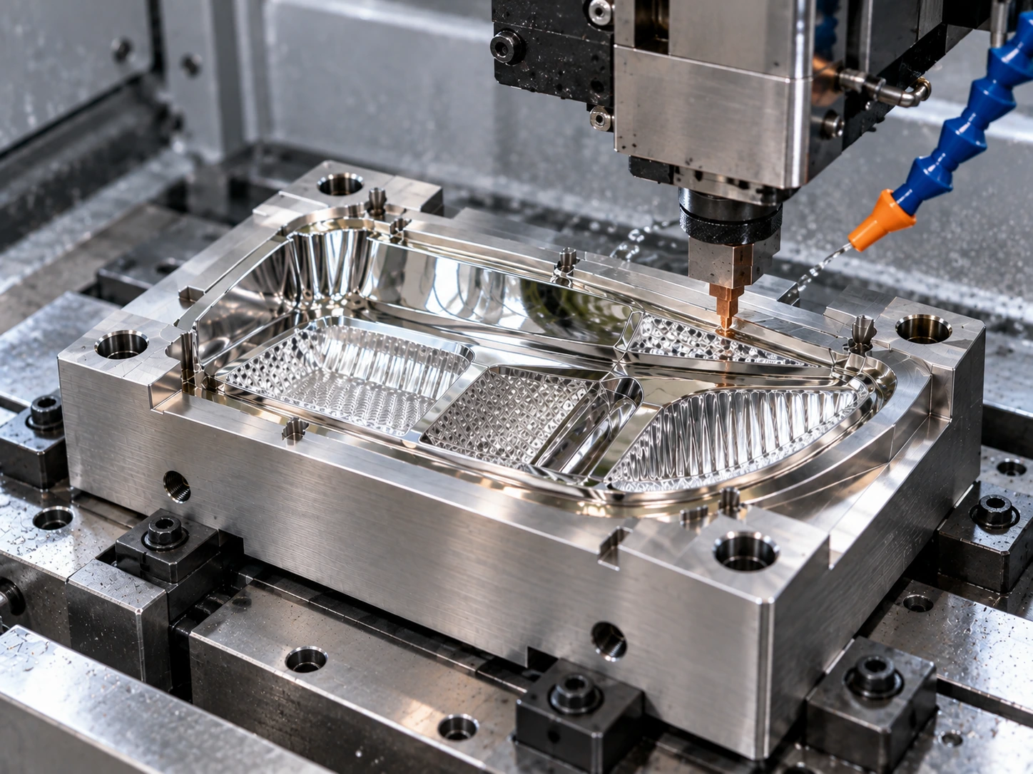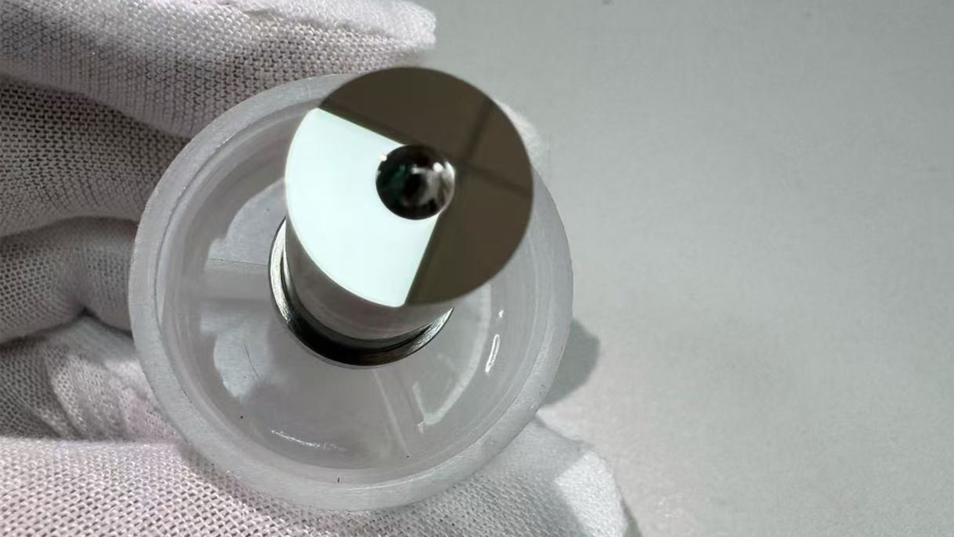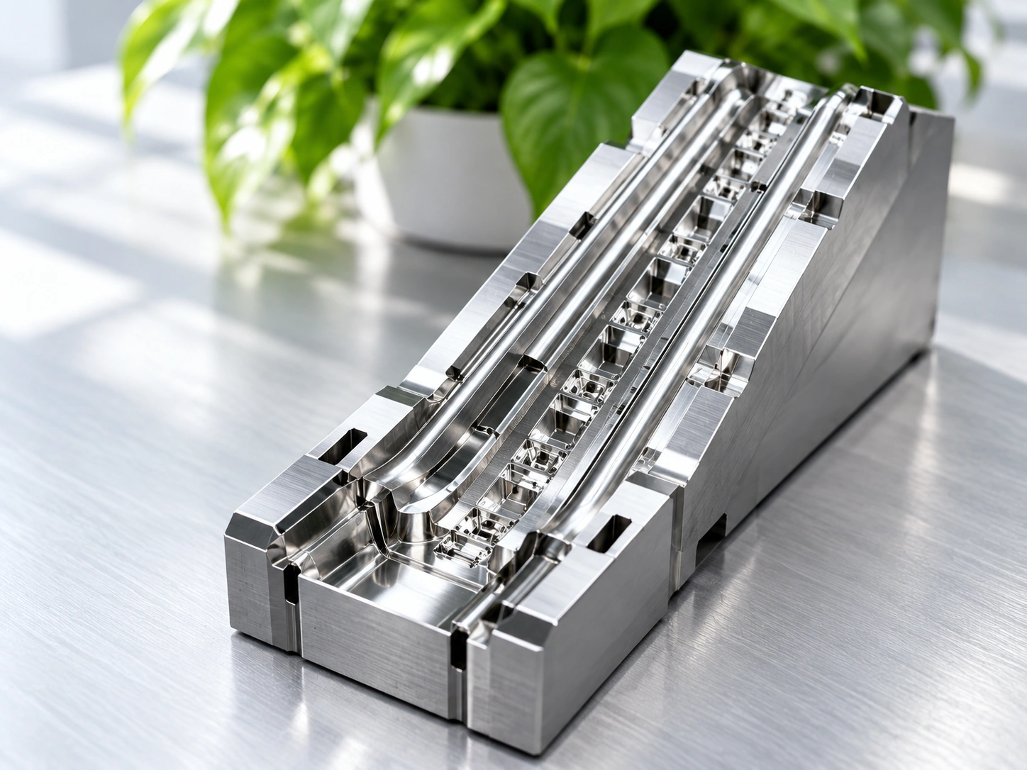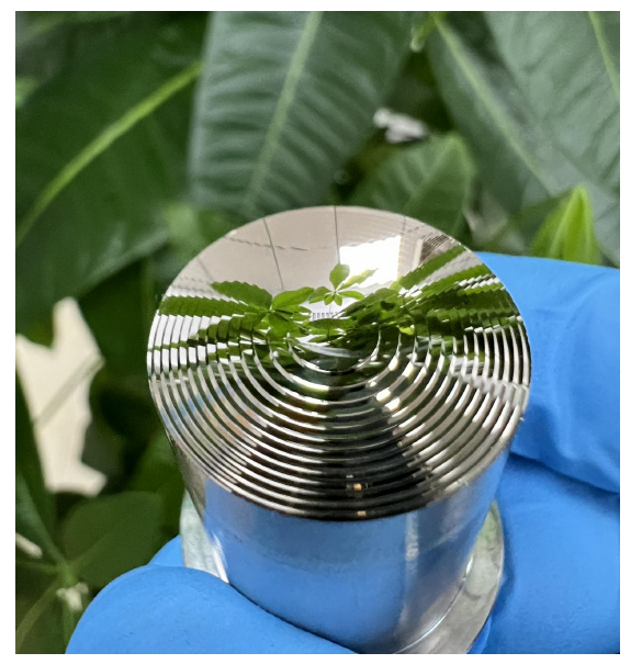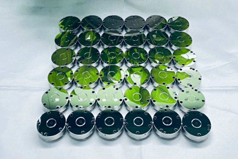
Eliminating micro-chatter and tool marks in mirror finish machining requires stabilizing the dynamic interaction between tool edge geometry, spindle harmonics, and material shear physics. While standard machining tolerates micro-vibrations below one micron, sub-micron mirror finishing exposes any deviation as visible diffraction grating patterns or hazy surface clouds. Achieving an optical-grade finish with surface roughness down to sub-micron Ra levels demands dynamic balancing of rotating assemblies, precise selection of ultra-hard tool substrates, control of cutting chip thickness, and structured troubleshooting of structural vibration.
This technical guide breaks down the physical root causes of surface defects in precision finishing, provides a diagnostic framework for machine and tool setup, and outlines when conventional CNC setups reach their physical limits.

The Physics of Surface Defects: Micro-Chatter vs. Residual Tool Marks
Diagnosing surface imperfections on reflective surfaces requires distinguishing between forced vibrations, dynamic chatter, and geometric tool impressions. Treating a vibration issue by changing toolpath stepover increases cycle time without solving the optical defect.
- Micro-Chatter: A self-excited or forced vibration pattern that manifests as periodic waviness or irregular “orange peel” textures across the cut surface. It occurs when dynamic cutting forces match structural resonance frequencies within the tool assembly, spindle bearings, or workpiece.
- Residual Tool Marks: Geometric cusps left behind by the physical profile of the cutting tool’s corner radius as it indexes across the workpiece at a set feed rate. Unlike chatter, tool marks are mathematically predictable based on tool nose radius and stepover distance.
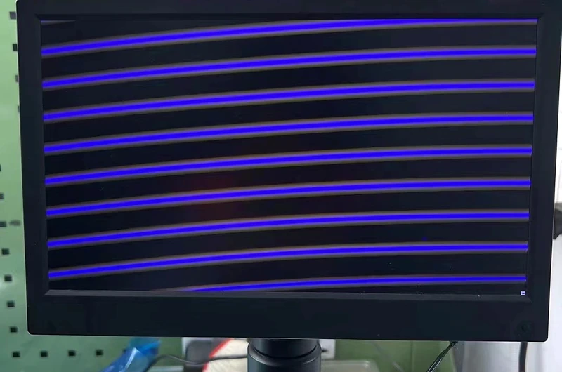
- Diffraction Effects: Microscopic feed pitches spaced at intervals comparable to visible light wavelengths (0.4 to 0.7 microns) act as reflection diffraction gratings. This separates ambient light into rainbow bands, even when stylus profilometry reads a low Ra value.
| Defect Manifestation | Underlying Mechanism | Primary Physical Indicator | Primary Inspection Method |
| Periodic ripple bands / waviness | Regenerative chatter or spindle vibration | Spacing changes with spindle RPM; non-uniform depth | White light interferometer, 3D optical profilometer |
| Rainbow / chromatic dispersion | Regular feed cusps matching light wavelengths | Constant spacing strictly tied to feed per revolution | High-intensity LED grazing light, optical scatterometer |
| Hazy or cloudy patches | Material plowing, micro-welding, or edge chipping | Irregular micro-scratches, torn surface grain | Scanning electron microscopy (SEM), phase-shifting interferometry |
| Parallel linear micro-scratches | Built-up edge (BUE) detachment or swarf dragging | Continuous or intermittent tracking along cutting vector | High-magnification optical microscope (500x+) |
Root-Cause Checklist: Why Micro-Chatter Occurs in Mirror Finishing
Micro-chatter stems from insufficient dynamic stiffness across the tool-holder-spindle-workpiece closed loop. In mirror finishing, vibration amplitudes as small as 50 nanometers ruin surface specular reflectivity.
Spindle Runout and Dynamic Unbalance
Dynamic spindle runout exceeding 1 to 2 microns introduces centrifugal force variations that modulate cutting depth with every revolution. Even if a spindle turns true at low speeds, high-speed unbalance in the rotor, pull stud, or collet induces structural harmonics. Tool assemblies balanced to ISO 1940-1 Grade G2.5 or better at operating speeds are necessary to minimize forced vibration excitation.
Tool Assembly Overhang and Holder Rigidity
Tool holder deflection scales cubically with overhang length ($L^3/D^4$). Extended-reach setups amplify bending moments, shifting tool-point natural frequencies directly into typical cutting excitation ranges. Standard ER collet chucks often introduce micro-slippage and uneven clamping. Hydraulic chucks, shrink-fit holders, or precision mechanical clamping systems provide greater radial stiffness and uniform 360-degree grip, damping transient deflections.
Fixturing Deflection and Workpiece Resonance
Thin-walled sections, overhangs on mold inserts, or non-uniform clamping pressures create localized compliance variations. As the tool traverses unsupported zones, the cutting force deflects the workpiece elastically. When the material springs back behind the cutting edge, high-frequency resonance ensues. Workpieces require balanced mechanical backing, vacuum chucking, or specialized dampening fixtures to eliminate localized vibration modes.
External and Environmental Vibrations
Mirror finishes are sensitive to environmental noise. Nearby heavy stamping presses, overhead cranes, forklift traffic, and coolant pump motor pulses transmit ground vibrations through machine cast-iron beds. Without pneumatic vibration-isolation mounts and isolated machine foundations, low-frequency floor vibrations transfer directly to the tool-part contact point.
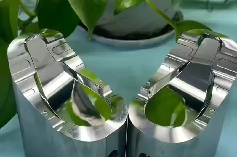
Tooling Dynamics: Selecting and Prepping Cutters for Defect-Free Surfaces
The microscopic state of the cutting edge dictates whether material separates via clean shear cutting or destructive plowing.
| Operating Mode | Edge Engagement Condition | Physical Mechanism at Contact Zone | Surface Impact & Defect Risk |
| Shear Cutting Mode (Correct) | Depth of cut ($a_p$) > Critical minimum chip thickness ($h_{min}$) | Material undergoes controlled shear plastic deformation; clean chip separation along the shear plane | Uniform specular finish, minimal subsurface stress, low Ra/Sa roughness |
| Plowing / Rubbing Mode (Incorrect) | Depth of cut ($a_p$) < Critical minimum chip thickness ($h_{min}$) | Material plastically smears beneath rounded edge; severe frictional burnishing and micro-tearing | Hazy appearance, high residual tensile stress, work hardening, micro-cracks |
Substrate Selection: MCD vs. PCD vs. Carbide
- Monocrystalline Diamond (MCD): MCD offers the sharpest cutting edge, with edge radii that can reach sub-nanometer levels. Because MCD lacks grain boundaries, it yields mirror finishes without micro-notching. It is ideal for non-ferrous alloys (oxygen-free high-conductivity copper, aluminum alloys) and electroless nickel coatings. MCD cannot be used directly on standard carbon or alloy steels due to chemical tool wear at high temperatures.
- Polycrystalline Diamond (PCD): PCD contains sintered cobalt and diamond grain boundaries. These microscopic boundaries can impart faint tracking lines, making standard PCD unsuitable for critical optical-grade specular surfaces, though it performs well for general non-ferrous wear resistance.
- Ultra-Fine Micro-Grain Carbide and cBN: For hardened mold steels (such as S136, NAK80, or 420 stainless), sub-micron grain tungsten carbide with advanced physical vapor deposition (PVD) coatings or cubic boron nitride (cBN) is required. Cutting edges require uniform microscopic preparation to prevent premature chipping under interrupted cutting forces.
Tool Geometry and Edge Radius Control
Every cutting edge has a finite radius ($r_n$). If the programmed uncut chip thickness ($h$) falls below the critical threshold ($h_{min} \approx 0.1 \text{ to } 0.3 \times r_n$), the tool stops cutting and begins plowing.
Plowing plastically deforms and burnishes the material instead of shearing clean chips, generating extreme local heat, micro-tearing, and tool marks. Tool nose radius ($r_\epsilon$) must be sized to balance structural stability against the radial component of the cutting force: excessive nose radii increase tool engagement length and radial forces, which can induce structural chatter on lower-rigidity machine axes.
Parameter Optimization Strategy to Eliminate Feed Marks and Resonance
Eliminating visible artifacts demands balancing cutting speed, feed-per-tooth, stepover, and lubrication dynamics.
1. Establish Minimum Chip Thickness to Prevent Rubbing
Calculate the effective chip thickness based on tool nose radius and lead angle. Ensure the feed rate keeps the cross-sectional cut above the material-dependent minimum chip thickness limit. Running feeds that are too fine leads to edge rubbing, rapid work hardening, and hazy surfaces.
2. Map Spindle Harmonics to Bypass Resonance RPM
Never select finishing spindle speeds arbitrarily. Machine tools exhibit stability lobes where specific RPM ranges remain completely free of chatter at varying depths of cut.
Identify stable speed zones by performing tap tests with an impact hammer and accelerometer setup, or by conducting test cuts across a step-machined coupon while sweeping spindle speeds in 500 RPM increments. Lock the finishing pass to the most stable harmonic plateau.
3. Calculate Stepover Distance for Theoretical Cusp Height
Calculate the theoretical surface roughness peak-to-valley height ($R_{th}$) using the tool nose radius ($r_\epsilon$) and cross-feed stepover ($b_r$):
$$R_{th} \approx \frac{b_r^2}{8 r_\epsilon}$$
To achieve sub-micron optical surfaces, maintain theoretical cusp heights well below 0.05 microns. After calculating stepover, verify that the resulting cusp spacing does not generate diffraction effects in visual inspection ranges.
4. Optimize High-Pressure Lubrication and Mist Delivery
Dry cutting or erratic flood coolant disrupts mirror finishing. Micro-droplets under high pressure or optimized minimum quantity lubrication (MQL) direct lubricants straight into the shear zone. This flushes chips away instantly, preventing recutting—a common cause of random gouges and scratches across mirror-faced mold cavities.
The Process Ceiling: When Conventional CNC Reaches Its Physical Limit
Standard CNC machining centers reach a mechanical barrier when specifications call for nanometer-level Ra values alongside tight form accuracy (PV errors).
| Feature / Metric | Mechanical Guide System (Conventional High-Speed CNC) | Air Bearing / Hydrostatic Guide (Ultra-Precision Machining) |
| Guideway / Bearing Interface | Direct rolling contact via recirculating steel ball or roller bearings | Zero physical contact; supported by an aerostatic gap or pressurized oil film (~10–20 μm) |
| Vibration Transmission | Mechanical contact transmits ball recirculating micro-shocks and rail waviness | Viscous fluid/air damping naturally absorbs and isolates high-frequency motor ripples |
| Dynamic Runout Profile | Typically within 1.0–3.0 μm at operating speeds | Sub-nanometer to low-nanometer range (< 20 nm achievable) |
| Drive Transmission Mechanism | Mechanical ball screws or standard linear motors with rolling ways | Coreless linear motors mounted on heavy granite or polymer concrete damping beds |
| Attainable Surface Roughness ($R_a$) | Typically bounded around 0.05–0.1 μm without manual polishing | Down to sub-micron optical specular quality ($R_a < 0.01\text{ }\mu\text{m}$) directly from the cut |
| Form Profile Fidelity (P-V) | Prone to contour errors at reversal points due to micro-backlash and stick-slip friction | Near-perfect form fidelity without contour deviation or edge rounding |
When core specifications demand sub-micron dimensional tolerances and mirror surfaces that eliminate post-polishing, manufacturing workflows transition to specialized platforms equipped with:
- Aerostatic (air-bearing) or hydrostatic liquid spindles featuring dynamic runout under 20 nanometers.
- Frictionless linear motor drives isolated from mechanical ball screws.
- Single-point diamond turning (SPDT) kinematic structures set on polymer concrete or granite machine bases.
- Enclosed environmental chambers maintaining thermal fluctuations below $\pm 0.1^\circ\text{C}$.
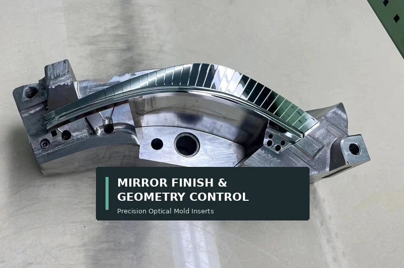
For injection mold components requiring strict beam dispersion or direct optical transmission, manual bench polishing is rarely viable because it rounds critical sharp edges and alters optical profiles. Projects requiring verified surface profiles typically rely on specialized custom optical mold core & insert machining to maintain geometric form fidelity while achieving optical finishes directly from the machine tool.
Quality Assurance: Measuring Micro-Chatter and Surface Roughness Objectively
Evaluating mirror surfaces requires non-contact metrology. Traditional diamond-tipped contact profilometers damage soft non-ferrous mirrors and bridge across narrow micro-chatter valleys, producing misleadingly smooth readings.
Non-Contact Optical Profilometry
White light interferometry (WLI) and coherence scanning interferometry (CSI) map 3D surface topographies down to sub-nanometer vertical resolutions. These instruments resolve surface roughness across an area, identifying both localized scratches and distributed micro-waviness.
Critical Metrology Metrics Beyond Basic Ra
Relying solely on average arithmetic roughness ($R_a$) masks optical defects:
- $S_a$ (Areal Average Height): Measures average roughness across a 3D surface area, capturing tool marks that align parallel to single 2D stylus traces.
- $S_q$ (Root Mean Square Roughness): More sensitive to random peaks, micro-pits, and gouges than $S_a$.
- $P-V$ (Peak-to-Valley / Form Error): Measures absolute deviation from ideal optical curvature, highlighting broad-scale structural chatter.
- Power Spectral Density (PSD): Decomposes surface topography into spatial frequencies. PSD graphs display distinct frequency spikes corresponding to machine vibration, spindle runout, or feed pitch, directly confirming the mechanical source of micro-chatter.
Partnering with Yishun for Sub-Micron Optical Mold Core Machining
Overcoming micro-chatter requires matching rigorous processing methods with dedicated machinery and metrology. When in-house machining centers face structural rigidity limits or tool-mark defects on critical mold cavities, outsourcing to an experienced production team mitigates risk.
Yishun provides precision manufacturing solutions for demanding mirror finish requirements. By using ultra-precision equipment, vibration-isolated manufacturing environments, and non-contact optical inspection platforms, Yishun assists component designers and moldmakers in producing core inserts free from micro-chatter and diffraction artifacts. Whether manufacturing optical inserts, precision light guides, or medical lens molds, Yishun delivers tool components that adhere strictly to required dimensional and surface quality specifications.
Key Takeaways
- Differentiate Defects First: Distinguish between feed-pitch tool marks (constant spacing dictated by feed rate) and micro-chatter (dynamic, self-excited vibration ripples) before adjusting cutting parameters.
- Avoid the Plowing Regime: Keep uncut chip thickness above the tool edge radius threshold to ensure shear cutting rather than burnishing and plastic smearing.
- Select Substrates by Material: Deploy Monocrystalline Diamond (MCD) for non-ferrous mirrors and nickel layers; rely on ultra-fine micro-grain coated carbide or cBN for hardened mold steels.
- Control Mechanics and Environment: Spindle dynamic balance (ISO G2.5), short tool overhang, rigid tool holders, and ground isolation are essential to eliminate harmonic excitation.
- Evaluate Spatial Frequencies: Use 3D optical surface profilers and Power Spectral Density (PSD) analysis rather than 2D contact stylus tools to locate the mechanical source of optical defects.
- Recognize Machine Limitations: Conventional ball-bearing machines impart structural noise; true optical surfaces with form accuracy often require specialized air-bearing or diamond turning setups.
FAQ
Can manual hand polishing eliminate micro-chatter marks without affecting dimensional accuracy?
Hand polishing can remove superficial micro-chatter marks, but it risks altering precision surface geometries. Abrasive polishing preferentially erodes sharp boundary corners, rolls fine edges, and introduces localized surface form errors (degrading PV values). For high-precision optical mold inserts, surfaces should ideally be cut directly to final mirror specifications on the machine tool.
Why do tool marks appear even when machine vibration sensors show near-zero amplitudes?
Visible tool marks can develop in the absence of machine vibration due to geometric feed cusps, micro-chipping along the tool cutting edge, built-up edge (BUE) formation, or material plowing. If the tool nose radius is worn or the depth of cut is shallower than the critical cutting edge radius, the tool smears material rather than cutting clean chips, creating visible tracks.
What is the fastest initial adjustment if chatter begins during a finishing cut?
The quickest initial response is to alter the spindle speed by 10% to 15% (either upward or downward) to disrupt regenerative chatter harmonics, while ensuring feed-per-tooth is maintained to prevent tool rubbing. Next, verify that tool overhang is minimal and inspect the cutting edge under high magnification for micro-chipping.
Why does a mirror surface look clear under diffuse light but show rainbow reflections under direct sunlight?
This indicates diffraction grating effects caused by uniform, closely spaced feed marks. When tool stepover or feed-per-revolution tracks match the wavelengths of visible light (0.4 to 0.7 microns), the surface acts as an optical reflection grating. Resolving this requires adjusting stepover spacing or transitioning to single-point diamond turning geometries.