In the rapidly evolving landscape of photonics, high-reliability optical, and medical technology, the transition from simple spherical optics to complex freeform geometries is reshaping manufacturing requirements. For decades, the spherical lens was the standard. Today, engineers are designing Augmented Reality (AR) waveguides, Head-Up Display (HUD) mirrors, and Micro-Lens Arrays (MLAs) that defy traditional manufacturing logic.
For engineers sourcing ultra-precision machining services, the challenge is no longer just about finding a shop that can hold tight tolerances. The challenge is choosing the right kinematic process to achieve those tolerances economically.
The two dominant technologies in this space are Single-Point Diamond Turning (SPDT) and Multi-Axis Ultra-Precision Milling (5-Axis Micro-Milling). While both utilize natural diamond tools to achieve sub-micron accuracy and nanometric surface finishes, they operate on fundamentally different physical principles.
This guide provides a deep technical comparison of these two methods, analyzing their mechanics, surface quality capabilities, and cost structures to help you determine the optimal manufacturing route for your next high-precision project.
1. The Contenders: Defining the Kinematics
To understand the pros and cons of each method, we must first distinguish how the tool interacts with the workpiece. In ultra-precision manufacturing, the “kinematics”—the relative motion of the tool and the part—dictates the final surface topology.
Single-Point Diamond Turning (SPDT)
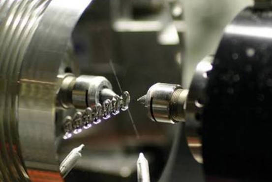
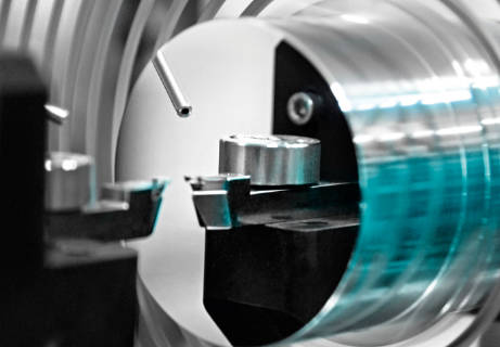
SPDT is the ultra-precision equivalent of a lathe. The workpiece is mounted on a vacuum chuck or fixture attached to an air-bearing spindle. This spindle rotates at speeds typically ranging from 1,000 to 10,000 RPM. A chemically stable, single-crystal diamond tool moves into the rotating part to shear away material.
- Kinematic Core: The part rotates; the tool translates.
- Key characteristic: The cutting process is continuous. The tool remains in contact with the material for the duration of the pass, resulting in a spiral tool path.
Multi-Axis Ultra-Precision Milling
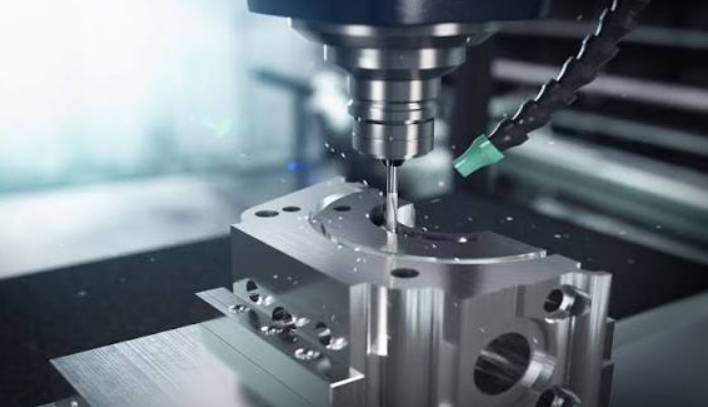
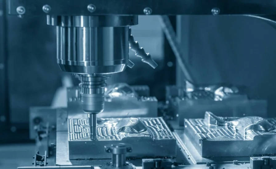
Ultra-Precision Milling (often referred to as 5-Axis Micro-Milling) operates on the principle of a milling machine. The workpiece is mounted on a stage that translates in X, Y, and Z (and often rotates in B and C axes). The diamond tool—either a ball-nose end mill or a fly-cutter—rotates at extremely high velocities (up to 100,000 RPM) on the spindle.
- Kinematic Core: The tool rotates; the part translates.
- Key characteristic: The cutting process is interrupted. The tool enters and exits the material thousands of times per second as it scans (rasters) across the surface.
Snippet for Google: The fundamental difference lies in the motion: In Single-Point Diamond Turning (SPDT), the workpiece rotates, making it ideal for symmetrical optics. In Multi-Axis Ultra-Precision Milling, the tool rotates while the workpiece moves, enabling the creation of complex freeform shapes and micro-arrays that lack rotational symmetry.
2. Deep Dive: Single-Point Diamond Turning (SPDT)
SPDT has long been the backbone of the precision optics industry. It is the deterministic process used to create the master molds for smartphone camera lenses and high-power laser mirrors.
The Pros of SPDT
1. Unmatched Surface Finish ($R_a$)
Because the diamond tool stays in constant contact with the workpiece, there are no vibration-inducing entry and exit shocks. This stability allows for the lowest possible surface roughness.
- Data Point: On standard non-ferrous metals like Aluminum 6061 or Oxygen-Free Copper, SPDT can routinely achieve $R_a < 2nm$ (nanometers).
- Optical Result: The surface acts as a perfect mirror with minimal light scatter, essential for laser applications.
2. Rapid Production for Symmetry
For rotationally symmetric parts—spheres, aspheres, parabolas—SPDT is incredibly efficient. A lens surface can often be finished in a matter of minutes. The material removal rate is consistent, and the programming is relatively straightforward compared to 5-axis work.
3. Diffractive Optical Elements (DOEs)
SPDT is uniquely suited for creating “Kinoform” lenses or diffractive patterns where concentric rings are required. The machine simply adjusts the depth of cut at specific radial distances to create the diffractive steps with sub-micron precision.
The Cons of SPDT
1. Geometric Limitations
The most significant limitation is the requirement for rotational symmetry. If your part is a square with an optical surface, or if the optical center is significantly offset from the mechanical center, SPDT becomes difficult.
- Note on Slow Tool Servo (STS): Advanced SPDT machines use a technology called Slow Tool Servo (STS) or Fast Tool Servo (FTS). This allows the Z-axis of the tool to oscillate in sync with the spindle rotation, enabling the turning of “non-rotationally symmetric” parts (like toric lenses). However, this is limited by the stroke length and frequency response of the machine, meaning extreme freeforms are still impossible.
2. Sensitivity to Edge Effects
In interrupted cuts (e.g., turning a mirror that has bolt holes drilled into the face), the diamond tool is subjected to mechanical shock every time it passes the hole. This can cause tool chipping and “ringing” marks on the surface downstream from the interruption.
3. Deep Dive: Multi-Axis Ultra-Precision Milling
As optical designs have shifted toward “Freeform Optics”—shapes that have no axis of rotational symmetry—Ultra-Precision Milling has emerged as the essential service.
The Pros of Multi-Axis Milling
1. Total Geometric Freedom
This is the primary reason engineers choose milling. It does not matter if the optical surface is saddle-shaped (biconic), cylindrical, or completely irregular. Because the tool rasters across the surface using 3, 4, or 5 axes of simultaneous motion, there are virtually no limits to the topology that can be created.
2. Micro-Lens Arrays (MLA)
Producing a monolithic array of 500 tiny lenslets on a single flat wafer is physically impossible with turning (you cannot spin the part around 500 different centers simultaneously). Ultra-Precision Milling is the standard method for manufacturing Micro-Lens Arrays, as the tool can machine each lenslet sequentially or raster across the entire array in a single pass.
3. Integrated Datum Features
One of the biggest headaches in optical assembly is aligning the lens. With 5-axis milling, a shop can machine the optical surface and the mechanical mounting datums (reference planes, pin holes) in the exact same setup.
- Benefit: This guarantees that the optical axis is perfectly aligned with the mechanical axis, reducing assembly errors and cost.
The Cons of Multi-Axis Milling
1. The “Rastering” Effect and Cusp Heights
Since the tool is a rotating ball-nose or radius cutter, it cannot cut the entire surface at once. It must move back and forth (raster). Between each pass, a tiny peak of material remains, known as the “Cusp Height” or “Scallop.”
- The Challenge: To make the surface optically smooth ($R_a < 5nm$), these cusps must be virtually invisible. This requires an incredibly small “step-over” distance (often < 1 micron).
- The Result: Cycle times skyrocket. Machining a 50mm x 50mm freeform mirror might take 10 to 20 hours of continuous milling to achieve the required finish, whereas turning it (if possible) would take 20 minutes.
2. Mid-Spatial Frequency Errors
Because of the complex interplay between the machine’s axes and the raster strategy, milled surfaces often exhibit “Mid-Spatial Frequency” (MSF) errors. These are ripples in the surface that don’t affect the form accuracy (PV) or the roughness ($R_a$) but can cause deviations in image quality for high-end imaging systems.
4. Head-to-Head Comparison: The Decision Matrix
When selecting an ultra-precision machining service, utilize the following matrix to evaluate which process aligns with your technical requirements.
| Feature | Single-Point Diamond Turning (SPDT) | Multi-Axis Ultra-Precision Milling |
| Primary Motion | Part Rotates | Tool Rotates |
| Surface Roughness ($R_a$) | Superior: < 1nm – 3nm typically achievable. | Good: < 5nm – 10nm (requires long cycle times). |
| Form Accuracy (PV) | Excellent (< 0.1 $\mu m$). | Very Good (< 0.3 $\mu m$), depends on thermal stability. |
| Geometry Capability | Rotationally Symmetric (Spheres, Aspheres). | Truly Freeform (Toroids, Arrays, Saddle shapes). |
| Cycle Time | Fast (minutes per part). | Slow (hours per part due to rastering). |
| Setup Rigidness | High (Continuous cut). | Lower (Interrupted cut / Dynamic forces). |
| Tool Wear | Low (Spread over long edge). | Higher (Concentrated impact). |
Snippet for Google: For purely rotational parts requiring the lowest possible scatter, Single-Point Diamond Turning is the superior choice regarding cost and quality. However, for Micro-Lens Arrays, non-circular apertures, and freeform shapes, Multi-Axis Ultra-Precision Milling is the only viable manufacturing method despite higher cycle times.
5. Material Compatibility: The Common Ground
It is crucial to note that both processes generally rely on monocrystalline diamond tools. Therefore, the material limitations are identical for both SPDT and Milling.
Compatible Materials:
- Non-Ferrous Metals: Aluminum (6061, 7075), Oxygen-Free Copper (OFC), Brass, Nickel, Tin, Gold, Silver.
- Plastics: PMMA (Acrylic), Polycarbonate, Zeonex, Polystyrene.
- Crystals: Germanium (Ge), Zinc Selenide (ZnSe), Silicon (Si), Calcium Fluoride (CaF2).
Incompatible Materials:
- Ferrous Metals: Steel, Stainless Steel, Titanium. (These cause chemical wear on the diamond).
- Glass: Typically too brittle for ductile-mode cutting (though grinding is possible).
The Solution for Steel: If you need a steel mold insert, the standard procedure for both processes is to plate the steel with Electroless Nickel (High Phosphorous). The machine then cuts the Nickel layer, not the steel substrate.
6. Application Scenarios: Which Service Do You Need?
To contextualize these differences, let’s look at three common engineering scenarios.
Scenario A: The High-Energy Laser Mirror
Requirement: A 100mm diameter flat mirror for a CO2 laser system. The surface must have absolute minimal scatter to prevent overheating.
Verdict: Single-Point Diamond Turning (SPDT).
Reasoning: The spiral tool path of SPDT creates a diffraction grating that is regular and predictable. The surface roughness can be brought down to 1-2nm. Milling would leave raster marks that could act as scatter sites, degrading laser performance.
Scenario B: The AR Waveguide Combiner
Requirement: A complex, non-spherical optical element that wraps around the user’s field of view in an Augmented Reality headset.
Verdict: 5-Axis Ultra-Precision Milling.
Reasoning: This is a classic “Freeform” application. The curvature varies across the X and Y axes independently. SPDT cannot generate this geometry. Milling allows the creation of the complex surface profile required to manage the light path in the waveguide.
Scenario C: The Infrared Camera Lens
Requirement: A Germanium meniscus lens for a thermal imaging camera.
Verdict: SPDT.
Reasoning: Germanium is brittle but machines beautifully in “ductile mode” under the high stability of a diamond lathe. Since camera lenses are rotationally symmetric aspheres, turning is the fastest and most accurate method.
7. The “Hybrid” Advantage
The most advanced ultra-precision machining services now offer a hybrid approach. Leading manufacturers utilize machines that combine a high-speed work-holding spindle (for turning) with a fully articulating B-axis and milling spindle (for milling).
Why choose a Hybrid Service Provider?
Imagine a metal optical housing that requires a precise aspheric mirror in the center (Turning) but also requires square reference pads and bolt holes on the outside (Milling).
- Legacy approach: Turn the part on machine A. Unclamp. Move to machine B. Re-clamp. Mill the features. Result: Loss of centration accuracy due to re-fixturing.
- Hybrid approach: The part is clamped once. The machine turns the mirror, then locks the spindle and mills the square features. Result: Perfect alignment between the optical axis and mechanical features.
When soliciting quotes, ask your vendor if they have “Hybrid Ultra-Precision” capabilities. This often reduces total project cost and improves yield.
8. Conclusion
The choice between Single-Point Diamond Turning and Multi-Axis Ultra-Precision Milling is rarely a matter of preference—it is usually dictated by the geometry of your design.
- Select SPDT if your part is round, requires the ultimate surface finish ($R_a < 2nm$), and demands cost-effective production speed.
- Select Ultra-Precision Milling if your part is freeform, non-circular, a lens array, or requires complex mechanical features integrated into the optical surface.
However, the most successful projects often start before the drawing is finalized. By consulting with a manufacturing partner early in the design phase, you can often tweak a geometry to make it compatible with SPDT, saving significant costs over a milled alternative.
At [Your Company Name], we specialize in bridging the gap between optical design and manufacturing reality. Our facility is equipped with state-of-the-art Diamond Turning Lathes and 5-Axis Ultra-Precision Milling centers, allowing us to offer an unbiased recommendation based purely on your performance goals.
Do you have a complex optical challenge?
Don’t guess on the manufacturing method. [Contact Our Engineering Team] today with your STEP or IGES files for a comprehensive manufacturability review and precision quotation.