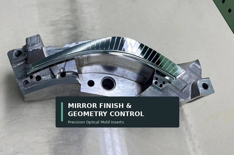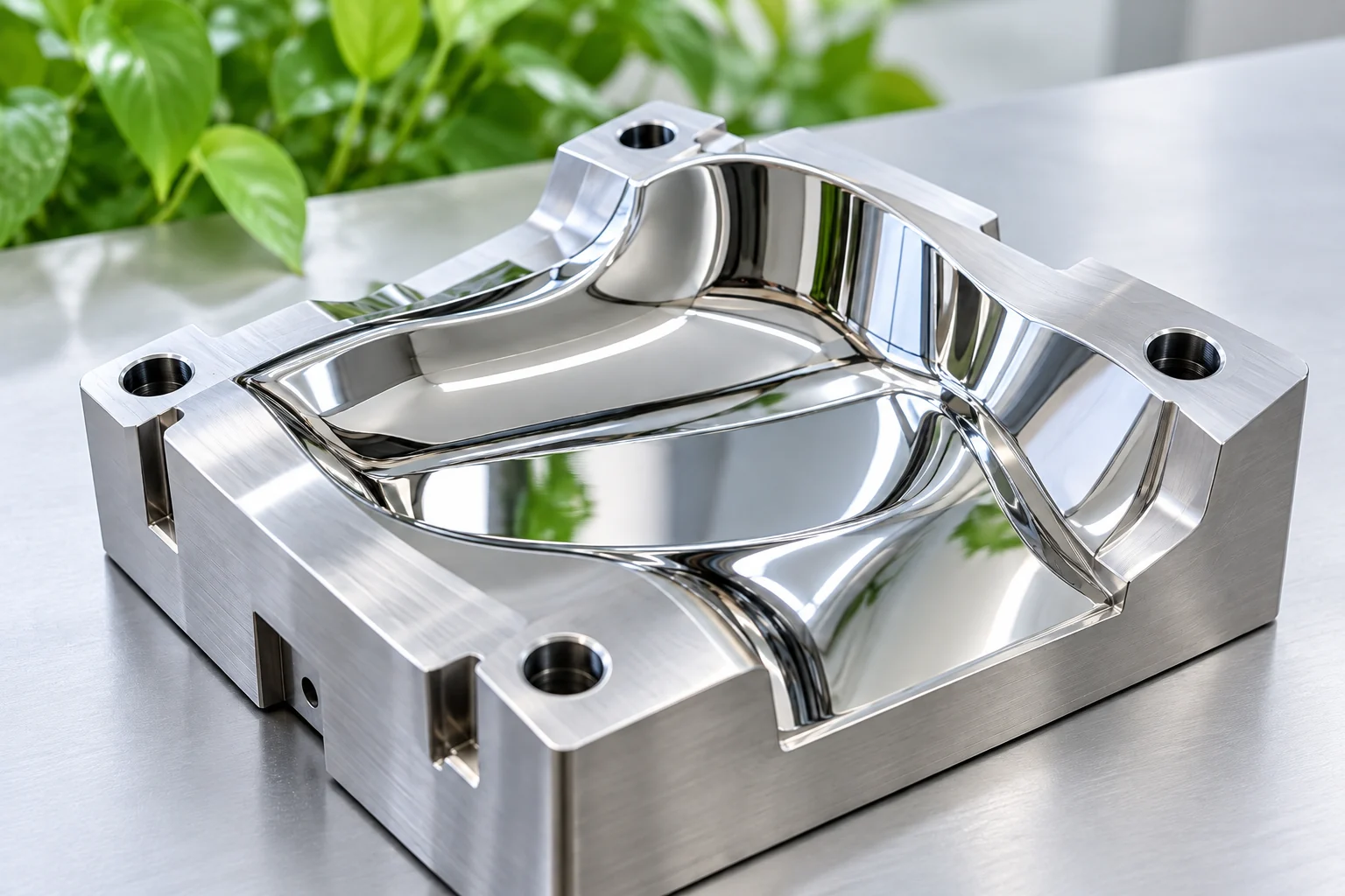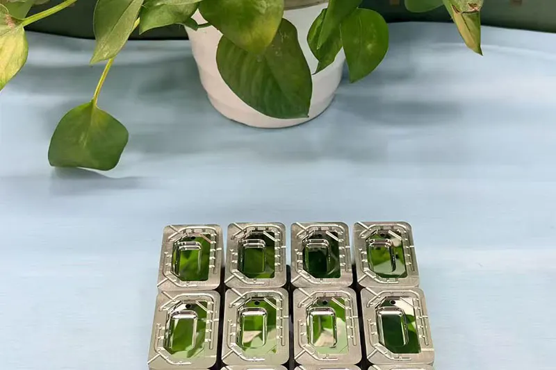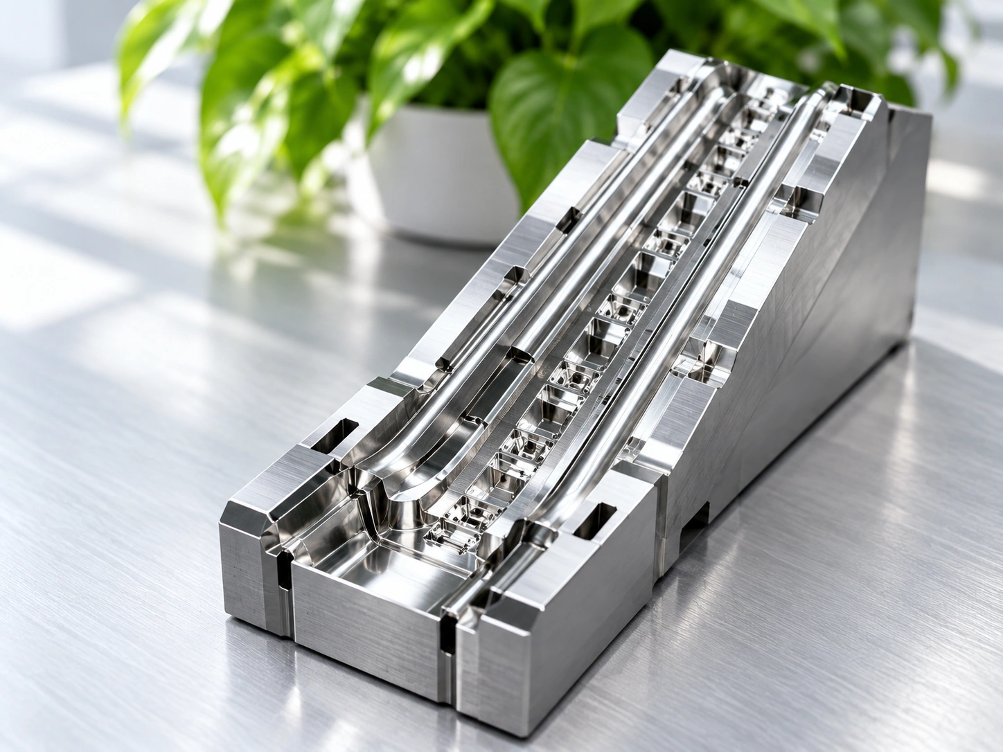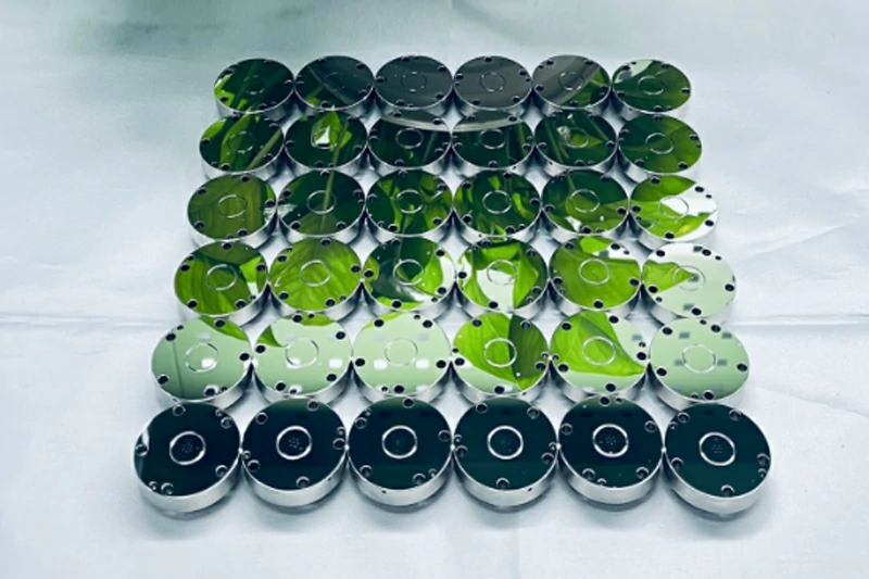
Achieving a true optical mirror finish on complex mold inserts requires balancing exact geometric form accuracy with sub-nanometer surface roughness. Single-point diamond turning (SPDT) provides deterministic profile generation for rotationally symmetric parts, but it leaves periodic micro-grooves that induce optical diffraction and is fundamentally restricted on ferrous mold steels. Conversely, precision optical polishing services eliminate micro-tool marks, refine isotropic surface roughness down to sub-nanometer levels, and process hard tool steels without chemical wear, though uncontrolled polishing risks edge roll-off and form distortion.
Choosing between SPDT and precision polishing depends on workpiece substrate composition, surface geometry, and the acceptable threshold for scattered light. This technical guide examines the kinematics, material boundaries, and hybrid processing routes that optical mold engineers use to deliver diffraction-free surfaces on challenging insert profiles.
The Optical Mold Dilemma: Balancing Surface Finish and Geometric Determinism
In injection molding and precision glass stamping, an optical insert transfers its exact negative surface directly onto the lens. For imaging optics, heads-up displays (HUDs), and precision sensor lenses, a “mirror finish” is not merely a high visual luster. It is defined by two distinct, tightly coupled engineering metrics:
- Form Accuracy (Peak-to-Valley / PV): The deviation of the bulk surface from the nominal mathematical CAD model (spherical, aspherical, or freeform).
- Surface Roughness ($Ra$ / $Sq$): The high-frequency micro-irregularities that govern light scatter, haze, and transmission efficiency.
| Process Category | Core Strengths | Process Limitations & Challenges |
| SPDT Processing | • Deterministic form control (PV) • Nanometric positional repeatability | • Residual micro-grooves (diffraction lines) • Restricted to non-ferrous materials |
| Precision Optical Polishing | • Sub-nanometer isotropic finish • Full eradication of periodic tool marks | • Risk of perimeter edge roll-off • Potential form geometry drift if unguided |
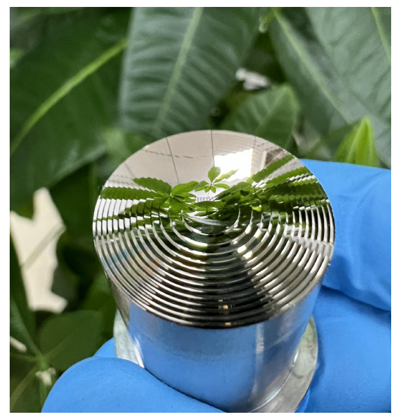
When specifying manufacturing methods, tooling engineers often face a tradeoff. SPDT machines geometries with sub-micron form accuracy directly from CNC toolpaths. However, diamond turning leaves periodic feed spirals that function as diffraction gratings under coherent or visible light. Precision optical polishing removes these high-frequency feed marks to establish isotropic finishes, but aggressive or unguided abrasive action can degrade delicate aspherical curves or round off sharp boundaries. Selecting the optimal manufacturing strategy requires assessing how each process generates surface topography at the physical level.
Process Mechanics: Surface Generation in SPDT vs. Precision Optical Polishing
SPDT and precision optical polishing modify workpiece substrates through fundamentally different physical mechanisms: single-point shear deformation versus multi-particle tribological abrasion.
| Characteristic | SPDT Kinematics (Deterministic Cutting) | Optical Polishing Kinematics (Abrasive Tribology) |
| Tooling & Interface | Single-crystal natural or synthetic diamond tool | Loose or fixed sub-micron abrasive particles (slurry/pad) |
| Action Mode | Continuous plastic shear deformation along CNC path | Multi-directional chemo-mechanical micro-planing |
| Generated Topography | Periodic micro-cusps aligned with tool radius and feed rate | Isotropic, non-directional, stochastic surface topography |
| Optical Impact | Potential diffractive scattering under visible illumination | Uniform light transmission with minimal diffractive flare |
Kinematics of Single-Point Diamond Turning (SPDT)
SPDT operates on ultra-precision CNC machine platforms equipped with air-bearing spindles, hydrostatic guideways, and laser interferometric feedback systems with nanometric resolution. The cutting mechanism relies on a single-crystal natural or synthetic diamond tool with an edge radius measured in tens of nanometers.
- Material Removal Mode: SPDT removes material by continuous plastic chip shearing within the ductile-machining regime, even on brittle crystals.
- Surface Topography Generation: Because the cutting edge follows a programmed path at a fixed feed per revolution, the generated surface retains regular micro-cusps. Even with feed rates reduced to single-digit micrometers per revolution, the profile exhibits periodic waviness and lateral spatial signatures corresponding to spindle speed and tool radius.
Mechanics of Precision Optical Polishing and Lapping
In contrast to deterministic single-point cutting, optical polishing relies on loose-abrasive planarization or soft-lap smoothing across an area of contact.
- Material Removal Mode: Polishing combines mechanical micro-scratching, chemical surface hydration (in chemo-mechanical scenarios), and hydrodynamic slurry flow. Sub-micron abrasive grains (such as diamond, cerium oxide, or aluminum oxide suspensions) slide across the interface under controlled pressure, micro-planing the peaks of surface asperities.
- Surface Topography Generation: Because abrasive particles strike the substrate at varied angles, the residual topography is fully isotropic and random. There are no directional ridges or periodic cusps, preventing optical diffraction patterns.
Technical Comparison: Tolerances, Material Compatibility, and Geometry
The decision to use diamond turning, abrasive polishing, or a sequential combination depends directly on the core technical metrics outlined below.
| Evaluation Metric | Single-Point Diamond Turning (SPDT) | Precision Optical Polishing |
| Typical Surface Roughness ($Ra$) | Typically 2 nm to 6 nm (subject to substrate grain size and tool wear) | Sub-nanometer capable (< 1 nm to 2 nm) (subject to material purity and lap choice) |
| Surface Signature | Directional, periodic tool marks (diffractive) | Isotropic, non-directional (zero-diffraction) |
| Material Compatibility | Non-ferrous only: Electroless nickel (NiP), copper, brass, PMMA, aluminum, germanium | Ferrous mold steels (Stavax, S136, 420 SS), cemented carbides, ceramics, optical glasses |
| Form Accuracy Preservation | Deterministic control down to sub-micron PV levels | Requires deterministic pitch/pad control to prevent form distortion |
| Geometric Suitability | Rotational surfaces, shallow off-axis profiles, slow tool-servo freeforms | Stepped features, tight non-continuous zones, internal radii, planar surfaces |
| Primary Process Defect | Periodic turning marks, micro-chatter, center-point cosmetic defects | Edge roll-off, orange peel, micro-scratches from slurry contamination |
Material Compatibility and the “Ferrous Barrier”
The most rigid boundary separating SPDT from optical polishing is substrate metallurgy. Diamond is pure carbon. When a single-crystal diamond tool cuts ferrous metals (such as standard mold steels like S136 or hardened stainless steel), the elevated temperatures and pressures at the tool-chip interface trigger rapid chemical wear. The iron acts as a catalyst, dissolving diamond into iron carbide and graphitizing the cutting edge within seconds.
Consequently, optical inserts processed solely by SPDT must be manufactured from non-ferrous alloys or electroplated with high-phosphorus electroless nickel (typically 10–14% phosphorus by weight) over a steel base. In contrast, specialized optical polishing and lapping solutions polish hardened tool steels directly up to 52–56+ HRC, eliminating the costs, delamination risks, and thermal expansion mismatches associated with secondary nickel plating.
Handling Complex Inserts: Deep Cavities, Micro-Structures, and Edge Roll-Off
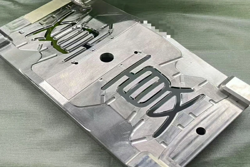
When optical inserts deviate from continuous, rotational hemispheres into complex geometries—such as multi-cavity arrays, steep draft walls, narrow ribs, or deep blind pockets—both processes encounter geometric constraints.
| Constraint Type | SPDT Clearance & Kinematic Restrictions | Optical Polishing Edge Roll-Off & Profile Risks |
| Root Cause | Tool shank collisions and clearance angle limits in steep cavities | Compression and localized pressure peaks at boundary peripheries |
| Physical Manifestation | Inaccessibility in pockets; center-point zero-velocity defects ($v = \omega r$) | Rounding of acute edges and premature erosion of boundary margins |
| Mitigation Method | Multi-axis STS/FTS configurations or specialized diamond shank geometry | Rigid pitch laps, sacrificial guard rings, and computer-controlled sub-aperture laps |
Kinematic Interference in SPDT
- Tool Shank and Clearance Angles: Diamond tools feature defined clearance and rake angles. In deep concave cavities or steep optical surfaces exceeding 45 degrees, the tool shank or clearance face can collide with the cavity wall, precluding access.
- Center-Point Defects: On rotationally turned inserts, the cutting velocity drops to zero as the tool passes through the spindle center of rotation ($v = \omega r$). This zero-speed condition often produces a small central blemish, tear, or residual peak that interferes with central optical transmission zones.
- Non-Rotational Features: Micro-prismatic arrays, cross-hatched geometries, and steep rectangular features cannot be turned on standard two-axis SPDT lathes. While fast-tool-servo (FTS) and slow-tool-servo (STS) systems allow non-rotationally symmetric generation, cycle times scale significantly, and dynamic tool acceleration can limit micro-groove depth resolution.
Edge Roll-Off and Form Degradation in Optical Polishing
A common challenge in polishing complex inserts is edge roll-off (rounding of sharp geometric borders).
- The Mechanism: When an abrasive lap or flexible pad traverses the boundary of an optical zone, pressure distribution peaks over the perimeter. The soft lap wraps slightly over the margin, compressing and eroding the edge faster than the central zone.
- Mitigation Strategies: Preventing edge roll-off requires rigid-lap techniques, pitch laps, sacrificial surrounding run-off plates, or localized sub-aperture computer-controlled polishing (CCOP). Hand polishing without mechanical kinematic guides almost always rounds micro-features and degrades designed clearances.
The Hybrid Workflow: Post-SPDT Optical Polishing for Zero-Diffraction Mirrors
To resolve the conflict between form accuracy and diffractive surface marks, high-end optical tooling facilities implement a hybrid manufacturing strategy: SPDT primary shaping followed by deterministic, sub-nanometer optical polishing.
| Phase | Operational Stage | Primary Objective | Process Parameters & Verification |
| 1 | Substrate Preparation | Core hardening and thermal stabilization | Vacuum heat treatment; stress relief; optional electroless NiP plating (75–100 $\mu$m) |
| 2 | SPDT Profile Generation | Deterministic form accuracy (PV) | Ultra-precision diamond turning to mathematically establish base geometry |
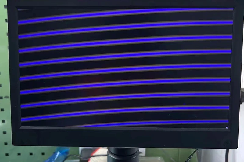
| 3 | Metrology Interlock | Quantitative tool-mark mapping | White-light interferometry (WLI) to resolve cusp wavelength and amplitude (10–50 nm) |
| 4 | Controlled Optical Polishing | Diffraction removal without form drift | Sub-micron slurry micro-planing removing 50–200 nm to level peaks while preserving PV |
| 5 | Final Quality Metrology | Full clear-aperture sign-off | Laser Fizeau interferometry (wavefront error) and optical profiler verification ($Ra < 1\text{ nm}$) |
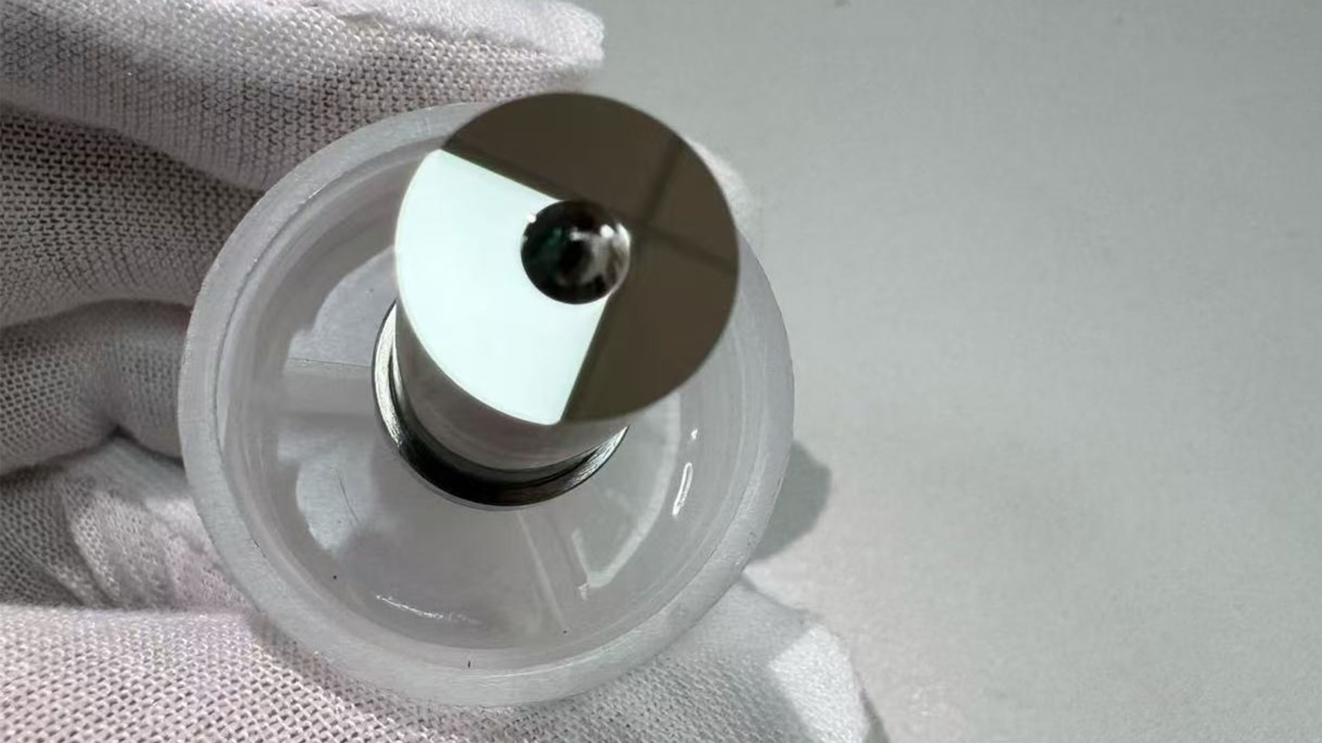
In Phase 4, the part transfers to precision optical finishing. Using pitch laps or compliant sub-aperture polishing heads loaded with sub-micron abrasive slurries, operators conduct custom mirror finish polishing for mold inserts. The removal depth is strictly constrained: the process removes between 50 nm and 200 nm of material—sufficient to plane down the peaks of the diamond turning cusps without drifting outside the overall PV form budget.
Engineering Decision Matrix: When to Specify SPDT vs. Optical Polishing Services
Use this engineering framework to evaluate part specifications, establish tooling routes, and optimize vendor work scopes.
| Substrate Material Class | Diffraction Sensitivity | Geometric Accessibility | Recommended Production Route |
| Ferrous Mold Steel (e.g., S136, Stavax, 420 SS) | High or Standard | Variable (pockets, cavities, ribs) | Precision Optical Polishing & Lapping Services (Direct finishing on hardened steel) |
| Non-Ferrous / Plated (NiP, Cu, Al, PMMA, Ge) | Low (IR optics, non-imaging) | Continuous rotational symmetry | Direct SPDT (No secondary abrasive finishing required) |
| Non-Ferrous / Plated (NiP, Cu, Al, PMMA, Ge) | High (Visible imaging, HUD prisms) | Continuous rotational symmetry | Hybrid Route (SPDT Form Generation + Controlled Polishing) |
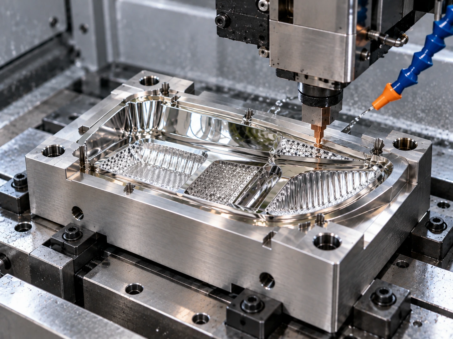
| Ferrous or Non-Ferrous | High | Deep non-rotational cavities | Multi-Axis Hard Milling / EDM + Precision Optical Polishing |
Procurement and Request-for-Quote (RFQ) Checklist
When preparing drawing packages for optical tooling vendors, supply the following parameters to ensure accurate capability matching:
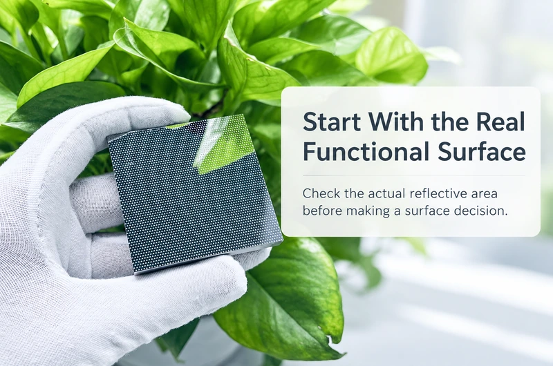
- Clear Aperture Boundary: Explicitly designate functional optical surfaces versus non-functional clamping margins.
- Surface Roughness Specification: Specify whether the target is $Ra$ (arithmetic average), $Rq/Sq$ (root-mean-square), or $Rz$ (maximum height of profile), and state the target instrument cutoff filter.
- Form Tolerance Metric: Define PV (peak-to-valley) or wavefront error tolerance, including the reference inspection wavelength (typically $\lambda = 632.8\text{ nm}$).
- Diffraction / Scatter Limits: State whether the insert serves imaging systems where directional turning cusps cause functional rejection.
- Base Material and Heat Treatment: Note alloy grade, core hardness (HRC), and coating thicknesses if nickel-plated.
Metrology & Verification: Quantifying Sub-Nanometer Precision
Validating an optical mirror finish requires moving beyond subjective visual checks to non-destructive, high-resolution optical metrology.
| Instrument Type | Measurement Domain | Primary Measured Parameters | Role in Quality Assurance |
| Laser Fizeau Interferometer | Macro-scale clear aperture | PV, Power, Astigmatism, Wavefront Error | Verifies that overall shape conforms to design tolerances without geometric drift |
| White-Light Interferometer (WLI) | Micro-scale areal topography | $Ra$, $Sq$, $Sa$, Turning Cusp Amplitude | Detects and confirms the total eradication of directional feed marks |
| Atomic Force Microscope (AFM) | Nanometer-scale sampling windows | High-spatial frequency $Rq$ (sub-nanometer) | Validates ultra-smooth performance for high-power laser and deep-UV optics |
Note on Tactile Metrology: Stylus profilometers should be used with extreme caution on mirror-finished optical inserts. The diamond-tipped stylus can drag across the surface, scratching soft nickel platings or leaving micro-grooves across fine steel finishes. Non-contact optical metrology is the standard for non-destructive inspection.
Key Takeaways
- Mechanism Distinction: SPDT uses deterministic diamond tool shearing to establish precise macro-form geometry (PV), whereas optical polishing relies on multi-particle tribological micro-planing to achieve isotropic, sub-nanometer surface finishes ($Ra$).
- Diffraction Risks: Residual micro-grooves from SPDT often act as diffraction gratings in visible-light applications; post-SPDT optical polishing removes these cusps to eliminate flare and scattered light.
- Material Boundaries: SPDT is chemically incompatible with direct iron-based steels and requires electroless nickel plating. Precision optical polishing processes hardened stainless steels (e.g., S136, Stavax) directly without coating interfaces.
- Geometry Constraints: SPDT is constrained by tool shank interference, rotational axes, and center-point zero-velocity defects. Precision polishing can address varied cavities and non-rotational surfaces, though edge roll-off must be managed using controlled lapping methods.
- Optimal Hybrid Route: The industry standard for high-performance visible optics combines SPDT for bulk deterministic profiling with low-pressure optical polishing to clear periodic tool marks within a strict material-removal budget.
Frequently Asked Questions
Can SPDT achieve an optical mirror finish directly on steel inserts without nickel plating?
No. Direct single-point diamond turning of ferrous alloys results in rapid chemical degradation. Iron catalyzes the conversion of diamond carbon into graphite and iron carbide, destroying the nanometric tool cutting edge within seconds. Ferrous inserts must either receive an electroplated high-phosphorus electroless nickel layer prior to turning or be processed directly using precision optical polishing and lapping methods.
Will precision optical polishing degrade the form accuracy (PV) of an aspherical insert?
Unguided, manual hand polishing frequently degrades form accuracy and rounds critical edges. However, controlled optical polishing—using conforming pitch laps, localized sub-aperture polishing heads, or computer-controlled kinematics—can plane high-frequency tool cusps while removing only 50 to 200 nanometers of material, keeping the profile well within the designed PV form budget.
What surface roughness is typically required for visible-light injection mold inserts?
For high-performance visible-light optics (such as imaging lenses, HUD combiner units, and sensor covers), optical inserts generally require a surface roughness of $Ra < 2\text{ nm}$ to $4\text{ nm}$, with zero periodic directional grooving. Critical low-scatter or laser applications may require sub-nanometer finishes ($Ra < 1\text{ nm}$).
What core parameters must be included in an RFQ for optical polishing services?
An RFQ package should supply: 3D CAD files and detailed 2D drawings defining the clear aperture boundaries; explicit surface roughness targets ($Ra$ or $Sq$) and measurement filters; allowable macro-form error limits (PV or fringe irregularity); base material composition and hardness (HRC); and any specific metrology requirements (such as white-light interferometry or Fizeau wavefront reporting).