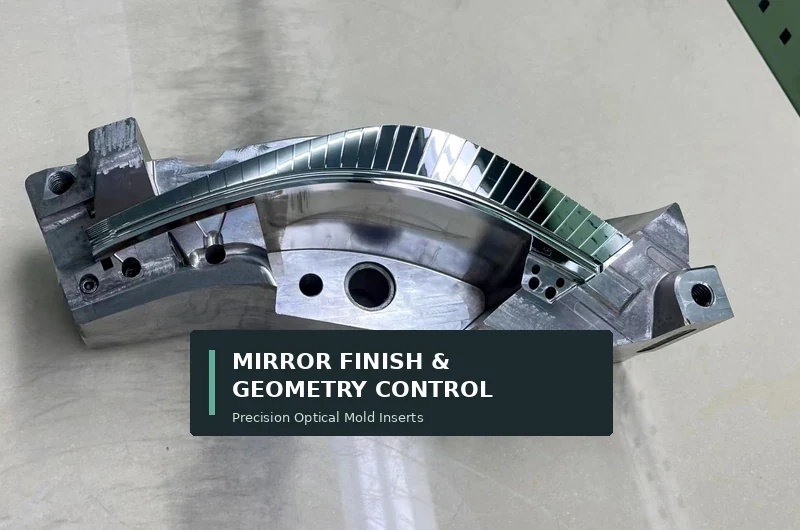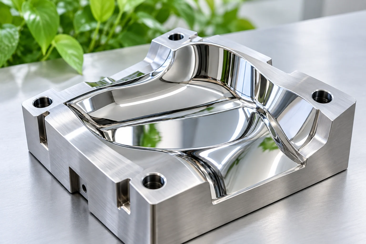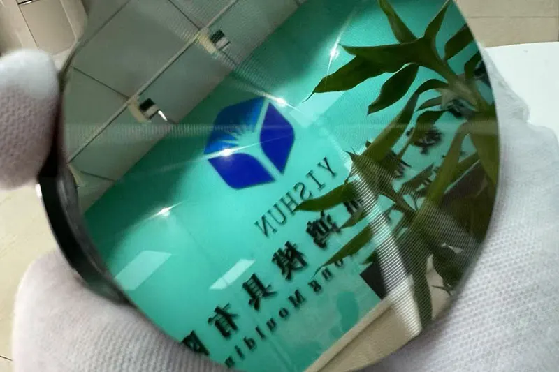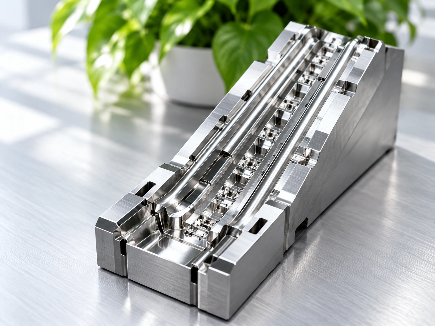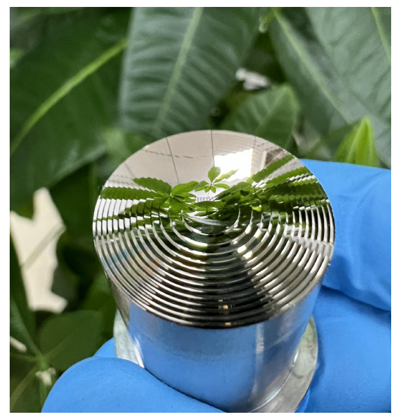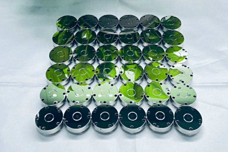
Ultra-precision mirror machining is an advanced subtractive manufacturing process that produces optical-grade mold cavities with sub-micrometer profile accuracy and nanometer-level surface roughness. In injection molding for augmented reality (AR), virtual reality (VR), and automotive head-up display (HUD) systems, the optical quality of the molded polymer element is directly determined by the mold cavity finish. Conventional CNC milling and manual polishing introduce surface form errors, edge rollover, and non-uniform microscopic profiles. To achieve direct-machined, polish-free tooling for micro-optical arrays and large freeform mirrors, tooling engineers rely on deterministic ultra-precision diamond machining methods.
Selecting the appropriate manufacturing route requires evaluating geometric complexity, substrate material properties, and metrology protocols. This engineering guide examines how single-point diamond turning (SPDT), diamond micro-milling, and nickel-phosphorus (NiP) plating integrate into the fabrication of high-performance mold inserts.
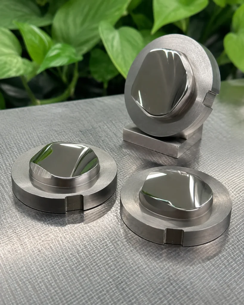
The Imperative for Ultra-Precision Mirror Machining in Next-Gen Micro-Optics and HUDs
Molded polymer optics for AR/VR and HUD systems must direct, reflect, and focus light with minimal wavefront distortion. When molding lenses with complex surface equations, the surface topology of the mold core is mirrored directly onto the final injected part.
Substandard mold cavity finishes create distinct optical transmission errors:
- Stray Light and Glare: Microscopic surface irregularities scatter incident light. In compact AR/VR optical systems, such as folded Pancake lens modules, light scattering produces visual ghosting and reduces contrast.
- Diffraction Artifacts: Irregular tool steps or periodic micro-grooves act as unintended diffraction gratings, projecting faint rainbow halos across virtual displays.
- Wavefront Distortion and Virtual Image Aberrations: In automotive HUDs, large aspheric or freeform combiner mirrors must reflect undistorted virtual dashboards onto the windshield. Profile deviations in the mold core introduce local focus shifts, leading to driver eye strain or distorted projection geometry.
To eliminate these optical errors, the mold insert must achieve an optical mirror finish directly from the machine tool. Standard CNC machining relies on manual abrasive polishing to remove residual tool cutter marks. However, manual polishing is inherently non-deterministic: it rounds off sharp microscopic transitions, destroys sag profile accuracy, and fails to maintain consistent form accuracy across non-rotationally symmetric surfaces. Direct ultra-precision machining eliminates manual polishing, preserving the mathematical curve of the optical design across the entire active aperture.
Tooling Specification Benchmark: Conventional Precision Tooling vs. Optical-Grade Mold Inserts
| Metric | Conventional Precision Injection Mold | Ultra-Precision Optical Mold Core | Practical Optical Impact |
| Surface Roughness ($Ra$) | Typically $0.05\text{ to }0.2\ \mu\text{m}$ (post-polish) | Sub-nanometer to low nanometer range (often $< 5\text{ nm}$, depending on setup) | Determines surface scattering, haze, and transmission contrast. |
| Form Error ($PV$) | Typically $1.0\text{ to }5.0\ \mu\text{m}$ | Sub-micrometer to sub-half-micrometer range | Governs image distortion, focal drift, and wavefront integrity. |
| Edge Sharpness / Transition Radii | Relies on manual touch-up; rounded corners | Sharp micro-step profiles preserved by fine diamond tool radii | Prevents aperture leakage and vignetting in segmented optical arrays. |
| Surface Reproducibility | Variable due to manual polishing operator variance | Fully deterministic CNC code and machine stability | Ensures repeatable cavity-to-cavity performance across multi-cavity inserts. |
Advanced Machining Technologies: SPDT vs. Ultra-Precision Diamond Milling
Achieving sub-micrometer optical surfaces requires deterministic cutting mechanisms powered by natural or synthetic monocrystalline diamond tooling, aerostatic or hydrostatic bearings, and sub-nanometer closed-loop position feedback systems. Tooling engineers choose between turning and multi-axis milling based on the rotational symmetry and continuity of the optical surface.
Optical Surface Geometry vs. Machining Process Selection
| Surface Geometry Category | Structural Characteristics | Primary Machining Route | Specific Process Setup | Typical Tooling Application |
| Axisymmetric / Continuous Rotational | Symmetrical profiles around a central optical axis; continuous curvature | Single-Point Diamond Turning (SPDT) | Standard 2-Axis SPDT | Spherical, standard aspheric lens cores, and flat mirror inserts |
| Non-Axisymmetric / Off-Axis Continuous Freeform | Smooth freeform geometry lacking rotational symmetry; moderate to high sag amplitude | Single-Point Diamond Turning (SPDT) | Slow Tool Servo (STS) | Automotive HUD combiner mirrors, off-axis parabolic reflectors, anamorphic lens cores |
| Non-Axisymmetric / High-Frequency Dynamic Freeform | Low-sag complex freeform surfaces or micro-structured ripples | Single-Point Diamond Turning (SPDT) | Fast Tool Servo (FTS) | Toric lenses, micro-structured wave plates, low-sag AR/VR prescription elements |
| Discontinuous / Segmented Arrays | Discrete 2D/3D repeating micro-features or segmented step heights | Diamond Milling Processes | Ultra-Precision Diamond Micro-Milling | Micro-Lens Arrays (MLA), prismatic light guides, segmented diffractive elements |
| Planar Facets / Linear Micro-Grooves | Flat reference planes or continuous linear grooved channels | Diamond Milling Processes | Diamond Flycutting / Planar Grooving | Faceted polygon mirrors, linear Fresnel prisms, ultra-flat datum surfaces |
Single-Point Diamond Turning (SPDT) for Axisymmetric and Freeform Optical Cores
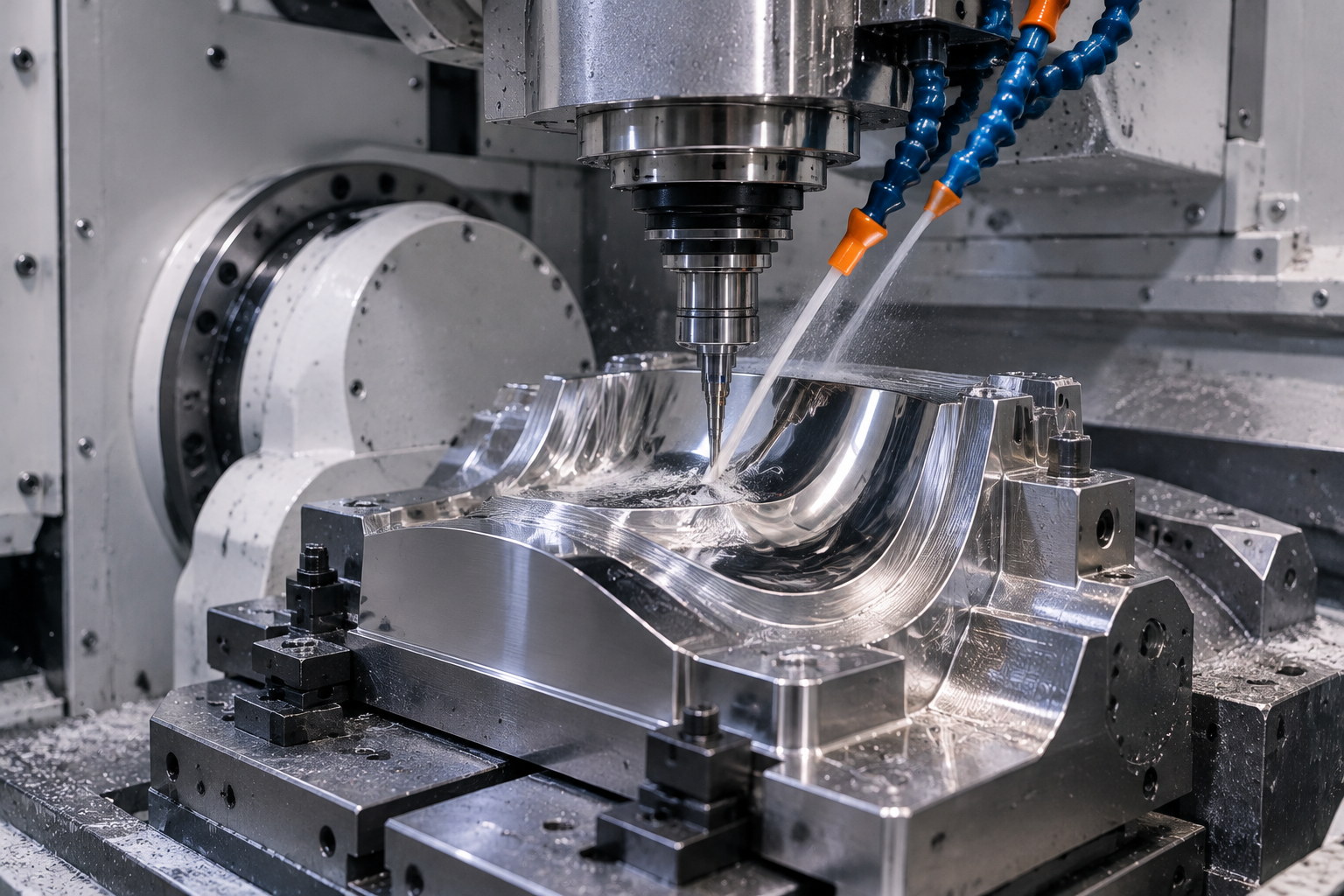
Single-Point Diamond Turning uses a single-crystal diamond tool to shear material at microscopic depths of cut. For continuous rotational profiles, standard 2-axis SPDT achieves superior surface roughness because the workpiece rotates continuously against a smooth, uninterrupted tool path.
For non-axisymmetric optical profiles—such as toric HUD mirrors or off-axis parabolic inserts—tooling fabricators utilize dynamic servo systems:
- Slow Tool Servo (STS): The machine’s linear axes move synchronously with the work spindle’s angular position (C-axis control). Because the entire machine slide oscillates to track surface elevation changes, STS accommodates large sag amplitudes (often several millimeters), though machining speed is constrained by the slide’s structural inertia.
- Fast Tool Servo (FTS): A secondary, high-bandwidth actuator (typically piezoelectric or voice-coil driven) mounts directly onto the tool slide. FTS moves the diamond tool at frequencies up to several hundred hertz. While travel stroke is typically limited to sub-millimeter depths, FTS reduces cycle times for high-frequency micro-structures and low-sag freeforms.
Multi-Axis Diamond Milling and Flycutting for Micro-Structure Arrays
When an optical mold requires features that cannot be swept rotationally—such as Micro-Lens Arrays (MLA), prismatic light guides, or cross-hatched Fresnel lens segments—ultra-precision diamond milling is required.
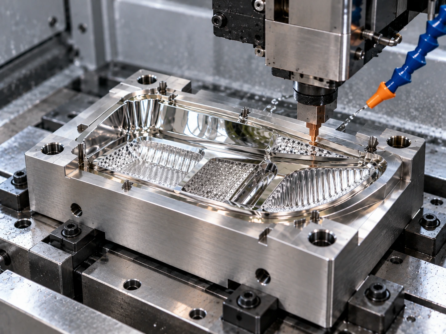
- Diamond Micro-End Milling: A high-speed air-bearing spindle spins miniature diamond endmills or ball-nose cutters to interpolate 3D freeform cavities. Tool path planning must carefully control radial step-over and feed per revolution to prevent scallop marks that degrade lens performance.
- Diamond Flycutting: The diamond tool mounts on the outer diameter of a rotating spindle disk while the workpiece traverses beneath it. Flycutting generates flat reference planes, linear micro-grooves, or faceted polygon reflectors with low surface roughness and straight edge geometry.
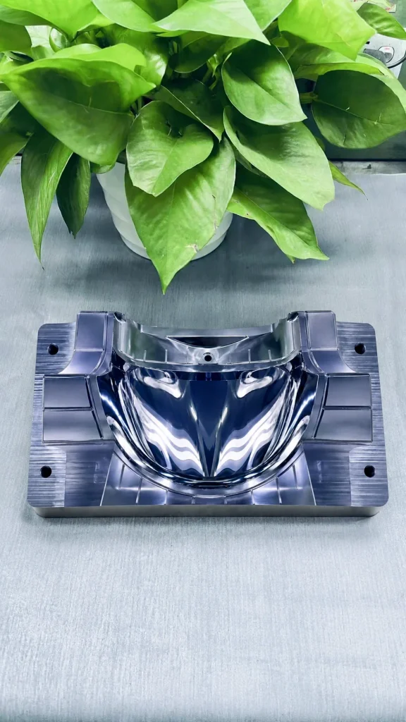
Material Compatibility: Substrates, Nickel-Phosphorus (NiP) Plating, and Tool Wear
A major constraint in ultra-precision mirror machining is the chemical compatibility between the cutting tool and the workpiece. Single-crystal diamond is composed of carbon. When diamond tools cut ferrous materials—such as standard pre-hardened or stainless mold steels—the extreme heat and pressure at the shear zone trigger a catalytic reaction:
$$\text{Carbon (Diamond Tool)} \xrightarrow[\text{Pressure, Heat}]{\text{Iron (Fe Substrate)}} \text{Iron Carbide / Graphitization}$$
This rapid chemical graphitization wears out the diamond cutting edge within minutes, destroying the optical finish.
To overcome tool wear while maintaining the mechanical strength needed for high-pressure injection molding, engineers apply specialized substrate and coating systems:
Multi-Layer Optical Mold Core Structure
| Layer Position | Structural Element | Typical Material & Thickness | Functional Purpose |
| Top Working Surface | Optical Mirror Machining Layer | Electroless Nickel-Phosphorus (NiP) coating ($75\text{ to }150\ \mu\text{m}$) | Provides an amorphous, grain-boundary-free matrix for diamond turning ($Ra < 5\text{ nm}$). Prevents tool graphitization. |
| Structural Substrate | Base Mold Core Blank | Pre-hardened corrosion-resistant tool steel (e.g., STAVAX, DIN 1.2083; $48\text{ to }52\text{ HRC}$) | Delivers structural stiffness, dimensional stability, and compressive yield strength to resist cyclic injection pressures. |
Substrate and Coating Selection Matrix
- Electroless Nickel-Phosphorus (NiP) Plating over Steel:
- Configuration: A structural tool steel base (such as DIN 1.2083 or STAVAX) is machined undersize, heat-treated, and coated with an amorphous electroless NiP layer ($75\text{ to }150\ \mu\text{m}$ thick, with a phosphorus content typically between 10% and 13%).
- Characteristics: The amorphous (non-crystalline) NiP coating lacks grain boundaries, allowing the diamond tool to cut cleanly without edge chipping or micro-void pullouts. The underlying steel core provides the compressive yield strength required to endure cyclic injection molding pressures.
- Non-Ferrous Alloys (Direct Machining):
- Configuration: Optical-grade Oxygen-Free High-Conductivity (OFHC) Copper, Aluminum 6061, or brass.
- Characteristics: These metals are diamond-machinable without catalytic tool wear. They are often used for prototype tooling, reflection testing, and low-volume silicone optics molding. However, their lower Rockwell hardness makes them susceptible to mechanical scratching and abrasive wear during high-volume injection runs.
- Direct Steel Machining (Alternative Technologies):
- Configuration: Direct machining of hardened steels using specialized cubic boron nitride (cBN) tools, laser-assisted diamond turning, or ultrasonic vibration-assisted machining.
- Characteristics: These setups reduce thermal graphitization during cutting. While effective for specific industrial geometries, they generally yield higher surface roughness than amorphous NiP cutting and require tight process tuning.
For precision projects requiring complex cavity geometries, utilizing custom optical mold core insert machining on NiP-plated steel substrates provides an effective balance of optical surface quality and tooling lifespan.
Application Matrix: Engineering Considerations for AR/VR vs. HUD Molds
Optical mold tooling requirements vary significantly depending on whether the element is intended for compact near-eye micro-displays or broad-aperture automotive projection.
Tooling Specification Comparison: AR/VR Micro-Optics vs. Automotive HUD Mirrors
| Engineering Parameter | AR/VR Micro-Optics Tooling | Automotive HUD Mirror Tooling |
| Typical Clear Aperture | Miniature to compact (often $\varnothing 5\text{ to }50\text{ mm}$) | Large aperture (frequently $> 200\text{ to }400\text{ mm}$ across major axis) |
| Surface Geometry | Sub-millimeter lens sags, steep local slopes, micro-lens arrays | Extended asymmetric freeform sag with continuous curvature |
| Critical Optical Vulnerability | Edge rounding at micro-transitions, stray light, and ghosting | Thermal drift during long cycles producing focal drift and image distortion |
| Primary Process Setup | High-speed diamond micro-milling, Fast Tool Servo (FTS) | Heavy-duty SPDT with Slow Tool Servo (STS) |
| Environmental Control Priority | High spindle dynamic balance and vibration isolation | Enclosed continuous thermal stabilization ($\pm 0.1^\circ\text{C}$ or better) |
AR/VR Micro-Optics: Pancake Lenses, Waveguide Coupling, and Micro-Lens Arrays
In near-eye displays, the optical system is positioned millimeters from the human eye, amplifying minute optical flaws:
- Geometric Features: Shallow sags, steep local surface slopes, and high spatial frequency micro-features (such as Fresnel lens ridges or dense lenslet arrays).
- Key Manufacturing Risk: Edge rounding at micro-groove transitions. If the tool nose radius or clearance angle is improperly matched to the lens pitch, the boundary between lens facets distorts, scattering light directly into the user’s field of view.
- Tooling Strategy: High-speed micro-milling or FTS setups operating in temperature-controlled enclosures to maintain sub-micrometer positioning over delicate, high-density structures.
Automotive HUD: Large Aperture Freeform Mirrors and Asymmetric Inserts
Automotive head-up displays project navigation and telemetry data through the windshield, requiring large off-axis, asymmetric aspheric mirrors:
- Geometric Features: Large surface areas (often exceeding $200\text{ to }400\text{ mm}$ across the major axis) with continuous, non-rotationally symmetric curvature.
- Key Manufacturing Risk: Thermal drift and machine tool kinematic errors over extended machining times. Cutting a large freeform mirror core can take tens of hours of continuous spindle operation. A temperature shift of just $0.5^\circ\text{C}$ during the finishing pass can cause thermal expansion in the machine axes or mold blank, creating uncorrectable wave-like form errors ($PV$).
- Tooling Strategy: Heavy-duty, high-stiffness SPDT/STS machinery housed in environmental chambers with thermal stability held within $\pm 0.1^\circ\text{C}$ or better, paired with optimized continuous-spiral diamond tool paths.
Application Comparison Matrix
| Application | Typical Optical Component | Primary Machining Method | Critical Failure Mode to Mitigate | Essential Machine Capability |
| AR/VR Near-Eye | Pancake Folded Lens, Micro-Lens Array | High-Precision Micro-Milling, FTS Diamond Turning | Micro-burrs and edge rounding causing stray light and ghosting | High-RPM air spindles, sub-micron tool edge sharpness |
| Automotive HUD | Combiner Mirror, Asymmetric Fold Mirror | Multi-Axis SPDT with Slow Tool Servo (STS) | Long-run thermal drift producing local curvature errors and focal distortion | Enclosed thermal stabilization ($\pm 0.1^\circ\text{C}$), dynamic C-axis synchronization |
Metrology and Inspection: Verifying Nanometer Tolerances and Surface Integrity
Fabricating an optical mold insert is only as reliable as the metrology used to verify it. Because sub-micron profile errors directly alter optical performance, quality control requires non-contact, optical-grade surface and form inspection.
Optical Metrology Systems and Inspection Scope
| Measurement Domain | Target Parameters | Primary Inspection Instrument | Principle of Operation | Quality Impact on Finished Optics |
| Micro-Topography | Surface roughness ($Ra$, $Sa$, $Sq$), feed marks, cutter striations | White Light Interferometry (WLI) / Optical Profilometry | Coherence peak detection of reflected light across micro-fields | Identifies and suppresses micro-groove diffraction artifacts and haze. |
| Global Form Profile | Form error ($PV$, $RMS$), aspheric/freeform sag deviations | Transmission Laser Interferometry / 3D Optical Probing | Computer-generated holograms (CGH) or chromatic confocal point sensors | Verifies mathematical profile fidelity to eliminate focus shift and visual distortion. |
Surface Roughness Metrology ($Ra$ and $Sq$)
Tactile surface profilometers (stylus-type) risk scratching delicate diamond-turned NiP finishes and cannot resolve sub-nanometer spatial details. Instead, optical metrology is standard:
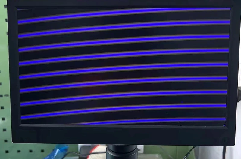
- White Light Interferometry (WLI): Measures coherence peaks of reflected light across a microscopic field of view, providing areal surface roughness ($Sa$, $Sq$) and linear roughness ($Ra$) data down to sub-nanometer resolutions.
- Diffraction Stripe Analysis: Inspects periodic turning patterns (feed marks). If the machine feed per revolution ($f$) and tool nose radius ($r$) are improperly balanced, residual periodic micro-grooves act as a diffraction grating. WLI surface maps allow engineers to refine tool feed rates to suppress these optical artifacts.
Form Accuracy Metrology ($PV$ and Sag Profiles)
Verifying geometric compliance against the mathematical lens model (STEP/IGES or optical prescription) requires high-accuracy profile metrology:
- Transmission Laser Interferometry: Utilizes computer-generated holograms (CGH) or transmission spheres to verify spherical and aspheric molds. The resulting interferogram reveals peak-to-valley ($PV$) surface error maps across the full active aperture.
- Non-Contact 3D Optical Profilometry: For non-symmetrical freeforms where standard null lenses cannot be applied, point-sensor or chromatic confocal optical probes measure coordinates along multiple meridians. These coordinates are then compared to the native CAD model to confirm dimensional compliance.
Engineering RFQ Checklist: What to Prepare Before Procuring Optical Mold Inserts
To expedite the design for manufacturing (DFM) review and avoid machining delays, engineering and sourcing teams should prepare a complete technical data package before requesting quotes for custom optical mold cores.
Optical Tooling Procurement Checklist
- Native CAD and Mathematical Data:
- Provide 3D STEP or IGES files representing both the finished optical core geometry and the mold base pocket interface.
- Include the explicit optical sag equation (polynomial, Zernike coefficients, or cloud-of-points table) for freeform profiles.
- Surface Quality and Form Callouts:
- Specify form accuracy in Peak-to-Valley ($PV$) or root-mean-square ($RMS$) error over the defined clear aperture.
- Define surface finish parameters using areal standards ($Sa$, $Sq$) or profile standards ($Ra$).
- Mark critical optical zones versus non-critical perimeter reference planes.
- Substrate and Tooling Interface Specifications:
- State preferred core base materials (e.g., DIN 1.2083, STAVAX) and specify whether NiP plating should be applied by the tooling partner.
- Define required core hardness ($HRC$) for the base steel to ensure mold longevity.
- Detail external alignment features, such as dowel pin holes, optical flat datum references, or kinematic mounting interfaces.
- Environmental and Inspection Requirements:
- Identify required inspection documentation (e.g., 3D interferometry error maps, areal surface roughness reports, coordinate measurement reports).
- Specify temperature reference conditions under which optical inspection must be performed (typically $20^\circ\text{C}$).
Key Takeaways
- Ultra-precision mirror machining eliminates manual abrasive polishing, preventing form distortion and maintaining tight tolerances across complex optical molds.
- Single-point diamond turning (SPDT) with Slow or Fast Tool Servos handles continuous rotation and freeform curves, while multi-axis diamond micro-milling is necessary for discontinuous features and micro-lens arrays.
- Ferrous mold steels react chemically with diamond tools. Machining an electroless nickel-phosphorus (NiP) coating applied over a pre-hardened steel core prevents tool wear while maintaining high tool life under cyclic injection pressures.
- AR/VR micro-optics demand precise edge geometry and scatter-free micro-structures, whereas automotive HUD tooling requires strict thermal stability over long machining cycles on large-aperture freeforms.
- Non-contact metrology, including white light interferometry and laser interferometry, is required to measure sub-nanometer finishes and sub-micron form profiles without damaging optical surfaces.
Frequently Asked Questions
Can ultra-precision diamond turned mold inserts be used directly for injection molding without manual polishing?
Yes. When optimized diamond tools, controlled machine kinematics, and compatible materials (such as electroless nickel plating) are used, the resulting surface roughness can drop below $5\text{ nm } Ra$. This direct-machined finish meets injection molding requirements for optical clarity, eliminating manual polishing that could otherwise compromise the surface figure.
Why is electroless nickel plating used instead of diamond machining steel mold cores directly?
Steels and other ferrous alloys contain iron, which catalyzes a chemical reaction with the carbon in single-crystal diamond tools under high cutting temperatures and pressures. This causes rapid tool graphitization and edge chipping. An amorphous electroless nickel-phosphorus (NiP) layer prevents this reaction, allowing the diamond tool to machine clean, scatter-free mirror surfaces.
How do tooling engineers prevent micro-grooves from creating diffraction effects in AR/VR lenses?
Diffraction artifacts stem from periodic feed marks left by the diamond tool nose during turning or milling. Engineers suppress these effects by decreasing feed rates, matching the tool nose radius to step-over geometry, and adopting specialized continuous spiral or randomized tool paths that break up spatial periodicity.
What is the primary difference between Slow Tool Servo (STS) and Fast Tool Servo (FTS) for HUD molds?
Slow Tool Servo utilizes the full stroke of the machine’s primary linear axes synchronized with spindle rotation, making it well-suited for the large sag depths common in automotive HUD freeforms. Fast Tool Servo uses a high-frequency, short-stroke secondary actuator (typically piezoelectric) to move only the tool holder, making it more efficient for low-sag or high-frequency surface variations.
What CAD and optical data are needed to evaluate an optical mold insert RFQ?
A complete data package includes standard 3D CAD files (STEP/IGES), explicit mathematical surface descriptions (such as aspheric equations or Zernike coefficients for freeforms), clear aperture boundaries, surface roughness specifications ($Ra$ or $Sa$), and allowable form deviation limits ($PV$ or $RMS$).